Note: Descriptions are shown in the official language in which they were submitted.
CA 02271882 2003-03-14
TIGHT PUNCTURE SEAL
TECHNICAL FIELD
The present invention relates to an arterial puncture closure for closing a
punctured
blood vessel in a human or animal body by means of his own blood.
BACKGROUND ART
DE-44 29 230, WO 96/05774 or WO 97/06735 (published later) describe puncture
closures for closing a punctured blood vessel. The pressure chamber of these
puncture
closures is filled with the blood running out of the blood vessel until the
pressure in the
pressure chamber equals the blood pressure in the blood vessel, so that a
balance of
pressure between the blood vessel and the pressure chamber is achieved. This
balance of
pressure stops the bleeding. The puncture closure disclosed in DE-44 29 230 or
in WO
96105774 has a nearly rigid retaining wall that is provided on their underside
with an
easily extensible pressure wall, preferably made of latex.
Before starting the therapeutic or diagnostic intervention the puncture
closure is
stuck onto the human or animal body in the area where the blood vessel will be
punctured.
Then, the cannula of the injection, the catheter or the like is pierced
through the pressure
chamber, particularly through the retaining wall and through the pressure
wall, before it
pierces the skin and the tissue of the patient to reach the blood vessel aimed
at. Now, the
required therapeutic step may be taken.
In order to avoid the risk of punching out of the retaining wall particles of
material
when piercing it with the cannula, it has been suggested to provide the
retaining and/or the
pressure wall with preformed openings. This has not proved practicable, since
the blood
may run out of these preformed openings, weakening the adhesive layers of the
puncture
closure so that the blood may run out without control.
When the treatment is over, the cannula is taken out of the body of the
patient and
of the puncture closure, whereas the puncture closure keeps sticking on the
body. Then,
the opening in the retaining wall is closed by a closing bracket equipped with
glue and is
arranged on the retaining wall. (See DE 44 29 230, WO 96/05774 or WO
97/06735.)
Single blood drops may ooze out of the pressure chamber and/or of the cannula
before the
CA 02271882 2003-03-14
closing bracket has sealed the opening. These blood drops are unhygienic and
represent a
risk of infection for the caring staff. These blood drops may also weaken the
glue so much
that the closing bracket can no longer be stuck in a pressure-sealed way onto
the retaining
wall.
DESCRIPTION OF THE INVENTION
An object of a broad aspect of the present invention is to provide a puncture
closure whose pressure chamber may securely be closed once the cannula has
been
withdrawn.
One broad aspect of the present invention provides an arterial puncture
closure for
closing a punctured blood vessel in a human or animal body by a cannula by
means of the
blood of the human or animal. The arterial puncture closure includes a
pressure chamber
which is configured to be fastened onto the body in the vicinity of the
puncture. The
pressure chamber is further configured to be loaded with excess pressure, a
part of said
pressure chamber which is opposite to said body being provided with a
retaining wall. A
closing element of at least 1 mm thickness, is provided, the closing element
being made of
material having an elastic restoring force. The closing element is arranged in
an area of
the retaining wall in which puncture by the cannula is planned.
A puncture closure made according to a broad aspect of the present invention
has
the advantage that the cannula pushes the material apart with elastic
restoring force or is
displacing it, when entering the closing element, thereby, avoiding in a
secure manner, the
punching out of material particles. When the material is pushed apart, the
energy involved
is stored in the material with elastic restoring force, so that the material
is reintegrating its
original position once the cannula has been withdrawn, thus closing the
opening made by
the puncture of the cannula (memory effect).
The material pushed apart by the cannula securely seals the place of puncture
and
protects it during the intervention against environmental influences since the
material with
the elastic restoring force always sits close to the cannula, because of this
restoring force.
In one preferred embodiment, the closing element is designed as a spherical
segment or as a lens and is arranged, more particularly glued, onto the
retaining wall,
thereby advantageously reinforcing the retaining wall.
2
CA 02271882 2003-03-14
As already explained in DE 44 29 230 or WO 96105774, an advantageous puncture
closure has a retaining wall that is substantially-non-extensible or that is
rigid in order to
prevent the pressure chamber from expanding away from the body of the patient.
This
substantially-non-extensible retaining wall enables the pressure chamber to
expand mainly
towards the body, and the tissue lying between the puncture closure and the
blood vessel is
compressed so that the blood cannot run into the tissue.
By reinforcing the retaining wall by means of a closing element according to a
broad aspect of the present invention arranged on the retaining wall, it is
possible to make
the retaining wall, just like the pressure wall, of an extensible material.
The extensible
retaining wall becomes inflexible by the closing element fastened onto it so
that the
pressure chamber can not expand significantly away from the body. The fact
that the
retaining wall and the pressure wall are made of the same extensible material
has the
advantage that the retaining wall and the pressure wall may be welded (e.g.,
by thermo-
welding or by ultrasonically-welding) together in alignment. Thus a puncture
closure
manufactured according to this broad aspect of the present invention may be
produced at
low cost, and the walls of the pressure chamber, joined together in a flow of
material, can
securely withstand the blood pressure prevailing in human and animal bodies.
A puncture closure with a retaining wall and an extensible pressure wall of
polyetherurethane having the same thickness and provided with a closing
element
arranged on the retaining wall has proved to have a sufficient extension
towards the body
when used under pressure. It may still be of advantage to make the retaining
wall thicker
than the pressure wall, since this measure further restrains the extension of
the retaining
wall.
The closing element may be covered by an outer layer which is substantially-
non-
extensible or rigid, and preferably is made of polyester or polyetherurethane.
The advantage thereof is that it is more difficult for the retaining wall to
extend
away from the body, particularly when the outer layer extends beyond the area
which is
assigned to the cannula puncture. The thus achieved sandwich-like structure of
retaining
wall - closure element - outer layer reliably prevents the retaining wall from
extending too
far away from the body.
Another advantage of the outer layer is that it protects the closing element
against
dirt and/or damage.
3
CA 02271882 2003-03-14
In one preferred embodiment of an aspect of the present invention, the outer
layer
is glued onto the particularly lens-shaped closing element with pressure or
pretension so
that the closure element is under a certain pressure or pretension. The
restoring effect of
the material with elastic restoring force of which the closing element is made
is reinforced
by this measure since, due to the prevailing pressure alone, the closing
element already
aims at closing the puncture opening made by the cannula as soon as it is
withdrawn from
the puncture closure. In order to reinforce this effect more, the outer layer
is
advantageously made of a substantially-non-extensible material as, for
example, of a
polyester foil or of a foil on polyester basis. The pressure built up on the
closing element is
thus maintained.
The outer layer extends up to the edge of the puncture closure or even beyond.
This has the advantage that the puncture closure may be easily seized with a
finger since it
has thus as a whole a palpable stability for the user. Another advantage
thereof is that an
adherend that extends beyond the edge of the pressure chamber may be used to
fasten the
puncture closure on the skin of the patient.
In another preferred embodiment of an aspect of the present invention, the
puncture closure is air permeable, at least partially and preferably in the
area outside the
pressure chamber. Thus, the puncture closure stuck on the skin advantageously
leaks
sweat or other vapours so that no moisture accumulates underneath the puncture
closure
that might attack the glue and so that the puncture closure does not
incommodate the
patient.
By another broad aspect of the present invention, the arterial puncture
closure,
further includes an outer layer which is arranged on said closing element. The
outer layer
is made of a material which is substantially-rigid and has a thickness of
between 10 ~m
and 100 ~cm. The arterial puncture closure may also include an outer layer
which is
configured to extend beyond the area in which the puncture by the cannula is
planned.
In a particularly preferred embodiment, the retaining wall and the pressure
wall are
made of the same extensible material, and the retaining wall is thicker than
the pressure
wall. Due to the difference in thickness the retaining wall and the pressure
wall have
different capacities of extension. This difference in extension between the
retaining wall
and the pressure wall has proved to be sufficient to guide the forces
occasioned by the
pressure within the pressure chamber onto the tissue so that the puncture
opening closes.
4
CA 02271882 2003-03-14
This is particularly true when the retaining wall and the pressure wall are
made of an
extensible polyetherurethane foil, a polyurethane foil or a polypropylene
foil. The
retaining wall has a thickness of 30 ~m up to 300 ,um and the pressure wall
has a thickness
of 5 ,um to 100 Vim. When the puncture closure is used for dialysis, the
retaining wall has
a thickness preferably of 40 ,um and the pressure wall a thickness preferably
of 25 ~cm.
When used in cardiology, the retaining wall of the puncture closure has a
thickness
preferably of 100 ~cm and the pressure wall a thickness preferably of 60 ~cm.
When
polyetherurethane is used, no particles are punched out by the cannula that
could get into
the blood stream.
A retaining wall and a pressure wall made of polyetherurethane, polyurethane,
polyether or polypropylene also has the advantage that these materials are air
permeable
and transparent, so that such a puncture closure is agreeable to wear on the
skin and that
the place of puncture on the body of the patient remains visible, even when
the puncture
closure is stuck. This preferred puncture closure is, for example, used for
hemodialysis on
dialysis patients.
In an alternative embodiment of the puncture closure according to a broad
aspect
of the present invention, the whole retaining wall is made of a material
having an elastic
restoring force. The retaining wall either has a uniform thickness or is
provided in the
puncture area with a corresponding swelling. The pressure wall stuck on the
underside of
such a retaining wall is extensible as compared to the retaining wall.
The material used for a retaining wall made of elastic material as well as for
the
closing element should be thick enough so that the opening made by the cannula
may be
closed again. Corresponding tests with a closing element made of silicone
showed that a
material thickness of approximately 4 mm is sufficient reliably to close an
opening made
by a cannula of an outer diameter of 1.8 mm as they are used for hemodialysis.
When
using the puncture closure according to an aspect of the present invention in
cardiology,
far larger opening diameters are made so that the thickness of material should
advantageously be of up to 25 mm.
Since the blood pressure in the arteries fluctuates between a peak value and a
minimum value depending on the pulse (e.g. between two pulse beats), a certain
amount of
blood runs out of the pressure chamber as soon as the pressure in the artery
momentarily
sinks due to the constant pressure built up in the pressure chamber. In order
to avoid this,
CA 02271882 2003-03-14
the pressure wall should advantageously be made of a layer having a thickness
of 0.2 mm
to 3 mm, preferably of 0.5 mm to 1 mm and being made of a material with
elastic
restoring force. Another possibility is to arrange a closing layer having a
thickness of 0.2
mm to 3 mm, preferably of 0.5 mm to 1 mm and made of a material with elastic
restoring
force inside the pressure chamber on the pressure wall.
In both cases, the blood runs out of the blood vessel into the pressure
chamber and
first keeps the opening open, since the restoring force of the material is not
big enough
completely to close the opening. When a certain pressure has built up in the
pressure
chamber, the closing element or the pressure wall are partially compressed so
that,
together with the restoring force of the material, the opening in the pressure
wall is now
closed. The closing layer or pressure wall functioning as a one-way valve
shortens the
time needed for the pressure chamber to get filled so that, within a very
short period of
time, a higher maximum pressure may be achieved in the pressure chamber. These
two
features improve the efficiency of the puncture closure according to a broad
aspect of the
present invention.
In another preferred embodiment of an aspect of the present invention the
retaining
wall is made of a material with elastic restoring force that is reinforced by
inelastic fibres.
These inelastic fibres may be long fibres arranged crosswise or they may
constitute a net,
for example.
The advantage thereof is that the retaining wall may be manufactured and more
particularly cast together with the closure element made of caoutchouc,
rubber, latex,
hydrogel, (fluid) silicone, polymer plastic or the like so as to form one
integral piece, but
that, due to the unelastic fibres, is hardly extensible so that the pressure
building up in the
pressure chamber only causes the pressure wall but not the retaining wall to
extend.
In still another preferred embodiment of an aspect of the present invention,
the
retaining wall and the pressure wall are glued together with a silicone glue
or with a
synthetic caoutchouc. Retaining wall and pressure wall are particularly glued
together
when the retaining wall and the pressure wall are made of different materials.
The problem
hereby is that the glue layer is very much exposed to stripping due to the
diac-like strain so
that it is not able to provide a strong enough adhesive force. When using
silicone glue or a
synthetic caoutchouc, and more particularly when the glue layer is 0.1 mm to 1
mm thick,
6
CA 02271882 2003-03-14
the line load is transmitted into a surface load via the thickness of the
layer so that the glue
may now much more easily control the occurnng forces and keep together the two
walls.
Since the bonding emulsion in the vicinity of the puncture opening only has a
sealing function and no force, a bonding emulsion is applied in the central
area of the
pressure chamber of a preferred embodiment, the bonding emulsion having less
adhesive
strength than the other bonding emulsion. The central area of the pressure
chamber may
also be kept free of glue. This has the advantage that the puncture closure
may be
withdrawn more easily from the patient's body, without the closed puncture
being strained
by strong forces.
DESCRIPTION OF FIGURES
In the accompanying drawings:
Fig. 1 shows a sectional side view of a puncture closure according to an
embodiment of an aspect of the present invention with integrated drug carrier;
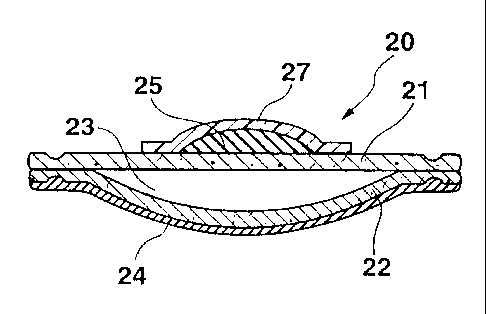
Fig. 2 shows a sectional side view of a puncture closure according to an
embodiment of an aspect of the present invention with an outer layer;
Fig. 3 shows a sectional side view of a puncture closure according to an
embodiment of an aspect of the present invention with a lengthened outer
layer;
Fig. 4 shows a sectional side view of a puncture closure according to an
embodiment of an aspect of the present invention with a closing layer
integrated in the
pressure chamber;
Fig. 5 shows a sectional side view of a puncture closure according to an
embodiment of an aspect of the present invention with a closure element
integrated in the
retaining wall.
The different figures of the drawing show parts of the subject matter
according to
broad aspects of the present invention in superproportional enlargements in
order to better
show its structure.
AT LEAST ONE MODE FOR CARRYING OUT THE INVENTION
The four different embodiments shown in Figures 1 to 4 all have the same core
structure, since all these puncture closures 10, 20, 30, 40 are provided with
a retaining wall
11, 21, 31, 41 that is only slightly extensible and that is made of a
polyetherurethane foil
7
CA 02271882 2003-03-14
of 40 ,um thickness. The retaining wall is welded in alignment with a pressure
wall 12, 22,
32, 42 made of a polyetherurethan foil of 25 ,um thickness so that a pressure
chamber 13,
23, 33, 43 is provided between the retaining wall 11, 21, 31, 41 and the
pressure wall 12,
22, 32, 42 that receives the blood running out of the blood vessel. The side
of the puncture
closure 10, 20, 30, 40 facing the body is provided with a skin-tolerated, bio-
compatible
glue 14, 24, 34, 44 preferably on an acrylate or silicone basis, by means of
which the
puncture closure 10, 20, 30, 40 may be fastened onto the skin of a patient. In
order for the
glue layer to remain movable and operative it has to be provided with a
protective foil that
is not shown here.
A closing element 15, 25, 35, 45 is glued or vulcanized onto the retaining
wall 11,
21, 31, 41, more particularly on its upper side, i.e., on the side of the
puncture closure 10,
20, 30, 40 that is opposite to the body. The closing element 15, 25, 35, 45 is
preferably
arranged in the centre on top of the corresponding pressure chamber 13, 23,
33, 43. This
closing element 15, 25, 35, 45 is made of silicone and reinforces on one hand
the retaining
wall 11, 21, 31, 41 while on the other hand, it closes the opening made by the
insertion of
the cannula after the cannula (not shown) has been withdrawn. In the
embodiments shown
in Figures 1 to 4, the closing element 15, 25, 35, 45 has the shape of a
segment of a circle,
i.e., the lower side of the closing element 15, 25, 35, 45 is planar and its
upper side is bent.
In other words, the closing element 15, 25, 35, 45 has the shape of a split
lens.
This basic version of a puncture closure according to a broad aspect of the
present
invention has a retaining wall 11, 21, 31, 41 and a pressure wall 12, 22, 32,
42 made of the
same material, but the retaining wall 11, 21, 31, 41 is thicker so that it is
less extensible
than the pressure wall 12, 22, 32, 42. This easy-to-extend polyetherurethane
is reinforced
in the area of the planned cannula insertion and beyond it by the spherical
segment-shaped
closing element 15, 25, 35, 45 made of silicone so that the retaining wall 11,
21, 31, 41
only extends slightly when the pressure chamber 13, 23, 33, 43 is filled.
Thus, the main
expansion of the pressure chamber 13, 23, 33, 43 is occurnng via the pressure
wall 1 2, 22,
32, 42 in direction of the body of the patient so that under no circumstances
can the blood
escape into the tissue, since the tissue is compressed.
By using similar materials for the pressure wall 12, 22, 32, 42 and for the
retaining
wall 11, 21, 31, 41, these two walls may easily be bonded together. Thus, a
tight enough
pressure chamber 13, 23, 33, 43 may be manufactured at low cost.
8
CA 02271882 2003-03-14
In the embodiment of the puncture closure 10 according to a broad aspect of
the
present invention and shown in Figure 1, a drug carrier 16 made of gauze or of
a tissue
matrix is integrated in the pressure wall 12. The drug Garner 16 may be soaked
with a
hematostatic for a faster blood coagulation or with another drug.
In the embodiment shown in Figure 2, the puncture closure 20 is provided on
its
upper side with an outer layer 27 made of a 40 ,um thick polyester foil that
completely
covers the closing element 25. The outer layer 27 sits so close to the closing
element 25
that the closing element is at least slightly compressed. The outer layer 27
is glued due to
the glueing effect of the silicone of the closing element 25. This pressure
exerted onto the
closing element 25 reinforces the restoring force of the silicone, since now,
additional
exterior forces are acting onto the opening made by the cannula in order to
close it. This
effect is still reinforced by the fact that, when the pressure chamber 27 is
filled, the closing
element 25 on the retaining wall 21 is compressed tangentially to the
retaining wall. Thus,
the pressure exerted onto the closing element 25 to close the puncture is
still further
increased.
In the embodiment shown in Figure 3, the outer layer 37 is much larger than
the
closing element 35 itself and extends beyond the edge of the retaining wall
31, so that the
outer layer 37 projects clearly beyond the retaining wall 31. In the
projecting area of the
outer layer 37, a glue 34 is provided on the side facing the body so that the
puncture
closure 30 may reliably be fastened onto the body of the patient.
In the embodiment shown in Figure 4, a closing layer 48 made of a material
with
an elastic restoring force, preferably of silicone, is integrated in the
pressure chamber 43
of the puncture closure 40. The closing layer 48 is located on the inner side
of the pressure
wall 42 and is arranged in the area in which the insertion of the cannula is
planned. This
closing layer 48 acts like a one-way valve and hinders the blood from running
out of the
pressure chamber 43 during the momentary drop of pressure in the blood vessel.
Figure 5 shows an alternative embodiment of a puncture closure 50 according to
a
broad aspect of the present invention. Here, the retaining wall S 1 is made of
a thick layer
of (natural) caoutchouc, latex or silicone. On its underside, an easily
extensible pressure
wall 52 is stuck that is made of a 25 ,um thick polyetherurethan foil so that
a pressure
chamber 53 is provided between the retaining wall S 1 and the pressure wall
52. In this
9
CA 02271882 2003-03-14
embodiment too, the underside of the puncture closure 50 is coated with the
above
mentioned glue 54.
In an alternative embodiment, the outer layer may be made, just as the
retaining
wall, of (natural) caoutchouc, latex or silicone. As opposed to the retaining
wall 51, the
pressure wall 52 is then only given a thickness of 0.5 mm.
All puncture closures 10, 20, 30, 40, 50 described above are used for example
in
dialysis or in cardiology. When used in dialysis, the puncture closure
according to a broad
aspect of the present invention is inserted on the forearm in the area of the
shunt, whereas
in cardiology, the puncture closure according to a broad aspect of the present
invention is
inserted on the thigh in the area of the femoral artery. When used in
dialysis, the cannulas
regularly used have a diameter of 1.8 mm, so that a closing element having a
thickness of
mm is sufficient to close the opening made by the cannula after completion of
the
intervention. In cardiology, the cannulas and/or catheters inserted into the
blood vessel are
much thicker and reach diameters of up to 5 mm, so that here, depending on the
case, the
closing element has to have a thickness of up to 25 mm in order to be able
reliably to close
the opening.
In an alternative embodiment (not shown), the puncture closure has a retaining
wall and a pressure wall, both of them being made of a 150 ,um thick
polyetherurethan or
incision foil. These two 150 ,um thick foils may be bonded or vulcanized
together several
times or in alignment, so that a strong connection between the foils is
achieved. That
connection is so strong that it may withstand the pressure forces occurnng in
the pressure
chamber when the puncture closure is used in cardiology.
All puncture closures 10, 20, 30, 40, 50 are transparent, in order to keep the
blood
vessel to be punctured at least approximately visible.
All the elements described in this application and made of a material with an
elastic restoring force are at least partially made of rubber, natural
caoutchouc, synthetic
caoutchouc, latex, silicone, liquid silicone, hydrogel, polymer plastic or of
a combination
of some of the above mentioned materials.
CA 02271882 2003-03-14
List of numerals
10, 20, 30, puncture closure
40, 50
11, 21, 31, retaining wall
41, 51
12, 22, 32, pressure wall
42, 52
13, 23, 33, pressure chamber
43, 53
14, 24, 34, glue
44, 54
15, 25, 35, closing element
45
16 drug carrier
27, 37, 47 outer layer
48 closing layer
11