Note: Descriptions are shown in the official language in which they were submitted.
CA 02272088 2005-07-12
WO 98!23122 PCF/SE97/01911
AMENDED PAGE
METHOD AND APPARATUS FOR INTER-EXCHANGE HANDOFF
TAKING INTO ACCOUNT THE SERVICE CAPABILITIES
OF THE CANDIDATE CELL
BACKGROUND OF THE INVENTION
Technical Field of the Invention
The present invention relates to cellular telephone networks and, in
particular, to inter-exchange handoff of mobile station call communications by
taking into account the service capabilities of candidate cells.
Description of Related Art
Cellular telephone networks support a number of known service capabilities.
Such differing service capabilities relate to: voice coder support (e.g., no
voice
coder, VSELP, or AFR); voice privacy support (e.g., no voice privacy, voice
privacy algorithm A}; data privacy support (e.g., no data privacy, data
privacy
algorithm A); hyperband support (e.g., 800 MHZ, 1900 MHZ, dual, and individual
bands (A, B, and the like) therein); and voice/data communications support
(e.g.,
analog, digital, facsimile, half/full rate, STU-1H). It is not uncommon for
the cells
included within the network to support different ones of those service
capabilities.
Thus, for example, one cell may support voice privacy while another, perhaps
adjacent, cell does not.
A cellular telephone call may implicate one or a number of these service
capabilities. For example, an AFR voice coder only capable dual band (800/1900
MHZ) mobile station may establish a particular call in a cell using 1900 MHZ,
AFR
voice coder and voice privacy service capabilities. In order for this example
call to
be maintained as the mobile station moves and a hand-off of the call from cell
to
cell occurs, each target cell must be capable of supporting 800 MHZ or 1900
MHZ,
AFR voice coder and voice privacy service capabilities (i.e., the same or
acceptable
alternate capabilities). A mobile switching center typically has knowledge of
the
service capabilities of each cell it serves, and thus making infra-exchange
hand-off
CA 02272088 1999-OS-17
WO 98/23122 PCT/SE97/01911
_2_
determinations can easily take into account difference in the service
capabilities
supported by each cell. That mobile switching center typically does not,
however,
have knowledge of the service capabilities of those cells it does not serve,
and thus
problems are encountered in making inter-exchange hand-off determinations to a
target cell capable of supporting the same (or acceptable alternate) service
capabilities as the currently handling cell. There is a need then for a
technique for
inter-exchange distribution of information concerning the service capabilities
of
individual cells. There is further a need for having this service capability
information considered in the context of inter-exchange hand-off to insure
continued
handling of cellular telephone call which require the use of certain ones of
those
capabilities.
SUMMARY OF THE INVENTION
In a cellular telephone network including cells individually supporting
certain
service capabilities, a message is sent from a first exchange to a second
exchange
distributing information on the service capabilities supported by a cell
serviced by
that first exchange. Alternatively, upon received request issued by the first
exchange, the second exchange provides the first exchange with information on
the
service capabilities supported by a cell serviced by that second exchange.
This
information on the service capabilities of other exchange serviced cells is
then
evaluated by the appropriate exchange in making determinations as to which
cooperating exchanges should be asked to make verification signal strength
measurements prior to hand-off, and also as to which candidate cells serviced
by
another exchange may comprise a target cell for that hand-off.
BRIEF DESCRIPTION OF THE DRAWINGS
A more complete understanding of the method and apparatus of the present
invention may be acquired by reference to the following Detailed Description
when
taken in conjunction with the accompanying Drawings wherein:
FIGURE 1 is a cell diagram illustrating an exemplary cell configuration for
a cellular telephone network in which the present invention may be
implemented;
FIGURE 2 is a signal flow and network operation diagram illustrating
operation of the network of FIGURE 1 in connection with a distribution of cell
service capability information between exchanges; and
FIGURES 3A-3B are signal flow and network operation diagrams illustrating
operation of the network of FIGURE 1 in connection with a verification-type
hand-
*rB
CA 02272088 1999-OS-17
WO 98!23122 PCTISE97/01911
-3-
off of a mobile statioli taking into account the service capabilities of hand-
off
candidate cells.
DETAILED DESCRIPTION OF THE DRAWINGS
Reference is now made to FIGURE 1 wherein there is shown a cell diagram
illustrating an exemplary cell configuration for a cellular telephone network
10 in
which the present invention may be implemented. The cellular telephone network
operates in accordance with one of a number of known air interface types
including, for example, a digital time division multiple access (TDMA)
protocol.
10 In a digital TDMA cellular telephone network, for example, each cell 12
operates
with an assigned set of transmission frequencies selected from one or more of
the
available cellular communications authorized hyperbands (e.g., 800 MHZ, 1900
MHZ, and the like) and frequency bands (A, B, and the like) therein. The set
of
frequencies assigned to each cell 12 includes frequencies supporting both at
least one
I S control channel and a plurality of traffic channels, with the control and
traffic
channels operable in either or both an analog andlor a digital mode. Sets of
assigned frequencies are different for adjacent cells 12, and such sets are
not
repeated for use by other cells except for those cells that are far enough
away from
each other to minimize the likelihood of adjacent or co-channel interference.
In the network 10, a base station 14 is provided for each of the cells 12. The
base stations 14 engage in simultaneous communications with plural mobile
stations
16 operating roughly within the area of the associated cell 12. The control
channel
assigned to each cell 12 is used to carry system control signals between the
base
station 14 and proximately located mobile stations 16, and also to assist in
the
network with mobile station cell reselection. Such control signals include
call
originations, page signals, page response signals, location registration
signals, traffic
channel assignments, maintenance instructions, and cell selection or re-
selection
instructions. The traffic channels provided in each cell 12 are used to carry
subscriber voice or data communications between the base station 14 and
proximately located mobile stations 16 and also to assist in the hand-off
operation.
The base stations 14 are illustrated as being positioned at or near the center
of each of the cells I2. However, depending on geography and other known
factors, the base stations 14 may instead be located at or near the periphery
of, or
otherwise away from the centers of, each of the calls 12. In such instances,
the base
3 5 stations 14 may broadcast and communicate with mobile stations 16 located
within
the cells 12 using directional rather than omni-directional antennas. Each one
of the
base stations 14 includes a transmitter, a receiver, and a base station
controller (none
CA 02272088 1999-OS-17
WO 98123122 PCT/SE97/01911
-4-
shown) connected to an antenna (also not shown) in a manner and with a
configuration well known in the art.
The base stations 14 further communicate via signaling links and voice trunks
22 with a central control station, commonly referred to as a mobile switching
center
18, which functions to control operation of the network 10. A boundary 34 is
shown in bold in FIGURE 1 to differentiate between those cells 12 (collected
in area
32(1)) served by a first mobile switching center 18(1), and those cells
(collected in
area 32(2)) serviced by a second mobile switching center 18(2). The mobile
switching centers 18 are interconnected with each other and to the public
switched
telephone network (PSTN) 20 by signaling links and voice trunks 24. The mobile
switching centers 18 operate to selectively connect subscriber voice and data
communications to the mobile stations 16 through its base stations 14. Thus,
the
mobile switching center 18 controls system operation through and in response
to the
transmission of control signals over the control channels to set-up on the
traffic
channels calls that are either originated by or terminated at the mobile
stations 16.
The mobile switching center 18 further controls, through and in response to
control
and traffic channel transmissions, the handoff of a subscriber communication
from
a traffic channel of one cell 12 to a traffic channel of another cell as the
subscriber
mobile station 16 roams throughout the cellular service area during an ongoing
communication.
The cellular network 10 may support through its cells 12 any one or more
of a number of known service capabilities. Such differing service capabilities
relate
to: voice coder support (e.g., no voice coder, VSELP, or AFR); voice privacy
support (e.g., no voice privacy, or voice privacy algorithm A); data privacy
support
(e.g., no data privacy, or data privacy algorithm A); hyperband support (e.g.,
800
MHZ, 1900 MHZ, dual, and individual bands (A, B, and the like) therein); and
voice/data communications support (e.g., analog, digital, facsimile, half/full
rate,
or STU-III). It is not uncommon, however, for the cells 12 included within the
network 10, even in some instances within one area 32, to support different
ones of
those service capabilities. A mobile switching center 18 has knowledge of the
service capabilities of each cell 12 it serves (i.e., those cells within the
area 32
associated with the mobile switching center). That mobile switching center
typically
does not, however, have knowledge of the service capabilities of those cells
12 it
does not serve (i.e., those cells within the area 32 associated with another
mobile
switching center).
Reference is now made to FIGURE 2 wherein there is shown a signal flow
and network operation diagram illustrating operation of the network 10 of
FIGURE
CA 02272088 1999-OS-17
WO 98!23122 PCT/SE97101911
-5-
1 in connection with a distribution of service capability information between
mobile
switching centers 18. In a first scenario illustrated near the top of FIGURE
2, a first
mobile switching center 18(1) transmits a parameter directive (PARMDIR)
message
60 to each of its cooperating (i.e., neighboring) mobile switching centers 18,
including mobile switching center 18(2). Included within this message 60, the
first
mobile switching center 18(1) specifies the service capabilities of one or
more cells
12 it serves (i.e., a cell or cells within the area 32 associated with the
mobile
switching center). The message 60 may be sent by a mobile switching center 18
at
any time, for example, after being updated to support a new service, or on a
periodic basis. This service capability information contained in message 60
concerning the identified cell 12 or list of cells is then stored (action 62)
by the
receiving mobile switching centers 18 in connection with, for example, the
making
of inter-exchange hand-off determinations as discussed in more detail herein.
The
receiving mobile switching centers 18 then reply back to the message 60
originating
mobile switching center 18(1) with an acknowledgment (ACK) message 64. In a
second scenario illustrated near the bottom of FIGURE 2, a first mobile
switching
center 18(1) transmits a parameter request (PARMREQ) message 70 to a
cooperating (i.e., neighboring) mobile switching center 18, such as mobile
switching
center 18(2). This request message 70 may be sent by a mobile switching center
18
at any time, for example, on a periodic basis. The receiving mobile switching
center 18(2) then replies back to the message 70 originating mobile switching
center
18( 1 ) with an acknowledgment (ACK) message 72. Included within this message
72, the second mobile switching center 18(2) specifies the service
capabilities of one
or more cells 12 it serves (i.e., a cell or cells within the area 32
associated with the
mobile switching center). This service capability information concerning the
identified cell 12 or list of cells is then stored (action 74) by the
requesting mobile
switching center 18(1) in connection with, for example, the making of inter-
exchange hand-off determinations as discussed in more detail herein.
Reference is now once again made to FIGURE 1. As the mobile stations 16
move within the service area of the network 10, instances arise where a mobile
station passes between two cells 12 within a single area 32, or from one cell
in a
first area 32(1) to another cell in a second area 32(2). In moving between the
cells
12, the mobile stations 16, in conjunction with base station 14 information
and
orders exchanged with and between the mobile switching centers 18, have an
3 5 opportunity through hand-off to change the base station through which
cellular radio
communications are being effectuated. For example, mobile station 16(1) is
shown
moving in the direction of arrow 26 from area 32(1) into area 32(2). Because
the
CA 02272088 1999-OS-17
WO 98/23122 PCT/SE97101911
-6-
cells 12 of the network 10 may each support different service capabilities, it
is
important in such instances of inter-exchange hand-off that the mobile
switching
centers 18 be informed not only of the services being utilized for the call in
the
currently serving cell, but also of the service capabilities supported within
the target
cell. If the service capabilities of the candidate cell do not support the
services
being utilized for the call in the currently serving cell, a handoff to that
candidate
cell may result in a dropped call.
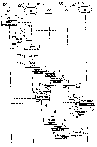
Reference is now made in combination to FIGURES 1 and 3A-3B, wherein
FIGURES 3A-3B are signal flow and network operation diagram illustrating
operation of the network 10 of FIGURE 1 in connection with a verification-type
hand-off of a mobile station 16(1), taking into account service capabilities,
from a
cell 12(1) within a first area 32(1) generally towards cell 12(2) within a
second area
32(2). The mobile station 16(1) is currently engaged in a call 100 implicating
certain service capabilities (such as hyperband, voice coder, privacy, and the
like).
The mobile station 16(1), operating if capable in accordance with known mobile
assisted hand-off (MAHO) principles, periodically makes downlink signal
strength
measurements 102 on the traffic channel (of cell 12(1)) that is currently
being used,
and also periodically makes downlink signal strength measurements 104 on the
control channels of network identified cells 12, including cell 12(2), which
neighbor
the cell 12(1). These signal strength measurements are reported 106 to the
base
station 14(1) for the currently serving cell 12(1). The base station 14(1)
concurrently makes uplink signal strength measurements 108 on the traffic
channel
that is currently being used by the mobile station 16(1).
The base station 14(1) processes the mobile station 16(1) reported 106
downlink signal strength measurements (102 and 104), if available, and the
base
station made uplink signal strength measurements ( 108) to determine first
whether
a hand-off is necessary (action 110) and second, if yes, to which candidate
cells the
hand-off could and/or should preferably occur (action 112). In this example,
it is
assumed that the base station 14(1) determines 110 from deteriorating measured
uplink and/or downlink signal strengths that a hand-off is necessary. It is
further
assumed that an identification 112 is made of a plurality of candidate cells
I2 for
hand-off. These candidate cells 12 may include cells in the same first area
32(1) as
the current cell 12(1), as well as cells in other areas 32, such as cell 12(2)
in second
area 32(2). A request 114 for hand-off including information comprising an
identification of the currently serving cell 12(1), the traffic channel being
used for
communication with mobile station 16(1) in cell 12(1), the time slot (for a
digital
traffic channel) carrying the cellular communication, and the list of
potential
CA 02272088 1999-OS-17
WO 98/23122 PCTISE97101911
-7-
candidate cells 12 for hind-off, is then sent by the base station 14(1) to the
serving
mobile switching center 18(1).
With respect to inter-exchange signaling and a potential for inter-exchange
hand-off, the currently serving mobile switching center 18(1) then determines
in
action 116, based on the stored {actions 62 and/or 74 of FIGURE 2) service
capability information for the cells of other mobile switching centers 18,
whether
a cooperating mobile switching center serving serves at least one cell 12 with
sufficient service capability (or acceptable alternate service capability) to
continue
handling the call 100 after a hand-off. If so, the mobile switching center
18(1)
signals 118 the cooperating mobile switching center 18 requesting verification
of
served base station 14 communications capability with the mobile station
lb(1). The
signal I18, like the request 114 sent by the base station 14(1), includes
information
comprising an identification of the currently serving cell 12(1), the traffic
channel
being used for communication with mobile station 16(1) in cell 12(1), and the
time
slot {for a digital traffic channel) carrying the cellular communication. For
example, if the call 100 requires an AFR voice coder and 1900 MHZ band, at
least
one cell 12 served by the cooperating mobile switching center 18, such as cell
12 (2)
for mobile switching center 18(2), must also support AFR voice coder and 1900
MHZ service capabilities in order for the mobile switching center 18(1) to
send the
signal 118. It is of course understood that an acceptable cell may comprise a
cell
having acceptable alternate service capabilities if available. If no such cell
12 exists
served by the cooperating mobile switching center 18, signaling and processing
resources are conserved in connection with the potential hand-off by not
sending the
signal 118 to that mobile switching center.
Responsive to receipt of the signal 118, the cooperating mobile switching
center 18, such as mobile switching center 18(2), determines in action 120
from the
identification of the cell 12(1), which of its served cells, such as cell
12(2}, are
neighbors (i.e., candidate cells) for hand-off. The cooperating mobile
switching
center 18(2) then signals 122 the base station 14, such as base station 14(2),
for each
of its served candidate cells, such as cell I2(2), to make a verifying signal
strength
measurement (action 124) on the traffic channel currently being used by the
mobile
station 16(1) in the currently serving cell 12(1). It is recognized that a
determined
neighbor cell 12 identified for receipt of the signal 122 may not necessarily
have the
service capabilities (either same or acceptable alternate) necessary for
supporting the
call 100 after hand-off. This is because the cooperating exchanges 18 send the
signals 122 to each candidate cell either (1) without being able to know which
of its
cells satisfy the service capabilities currently used by the mobile station
16(1) in cell
CA 02272088 1999-OS-17
WO 98/23122 PCT/SE97101911
_g_
12(1), or (2) without being provided in signal 118 with the list of cells for
the
cooperating exchange that were selected in action 116 by the serving mobile
switching center 18(1).
At or about the same time, the mobile switching center 18(1) has similarly
identified in action 120 which of its served cells 12 are neighbors (i.e.,
candidate
cells) to cell 12(1) for hand-off. The mobile switching center 18(1) then
similarly
signals 122 the base station 14 for each of its served candidate cells I2 to
make a
verifying signal strength measurement (action 124) on the traffic channel
currently
being used by the mobile station 16(1) in the currently serving cell 12(1). It
is again
recognized that a determined neighbor cell 12 identified for receipt of the
signal 122
may not necessarily have the service capabilities necessary for supporting the
call
100 after hand-off. This is because the cooperating exchange 18 sends
typically the
signal 122 blindly to each candidate cell without making a service
capabilities
evaluation.
I S In another embodiment of the present invention, the signal 118 includes
information not only comprising an identification of the currently serving
cell 12(1),
the traffic channel being used for communication with mobile station 16(1) in
cell
12(1), and the time slot (for a digital traffic channel) carrying the cellular
communication, but also an identification of the particular neighboring cells
12
served by the cooperating mobile switching center 18 having the service
capabilities
(either the same or acceptable alternate) necessary for supporting the call
100 after
hand-off. This information is obtained by the mobile switching center 18(1)
during
the processing of action 116 from the stored (actions 62 andlor 74 of FIGURE
2)
service capability information for the cells of other mobile switching centers
18. It
is recognized then that in this embodiment only those cells 12 served by the
cooperating exchange 18 capable of supporting the call 100 from a service
capability
(or acceptable alternate service capability) perspective after hand-off are
instructed
by signal 122 to make verifying signal strength measurements (action 124) on
the
traffic channel currently being used by the mobile station 16(1) in the
currently
serving cell 12(1). In a similar manner, the mobile switching center 18(1)
intelligently instructs by signal 122 only those cells 12 it serves that are
capable of
supporting the call 100 from a service capability (or acceptable alternate
service
capability) perspective after hand-off to make verifying signal strength
measurements (action 124) on the traffic channel currently being used by the
mobile
station 16(1) in the currently serving cell 12(1).
Each base station 14 instructed by a received signal 122 in either of the
foregoing embodiments then reports 126 the results of the verification signal
strength
CA 02272088 1999-OS-17
WO 98/23122 PCTISE97/01911
_g_
measurement to their sei~ring the mobile switching center 18. In the case of
reports
126 made to cooperating mobile switching centers 18, such as mobile switching
center 18(2), the reported verification signal strength measurements are
forwarded
128 on to the mobile switching center 18(1). The verification signal strength
measurement results are then processed {action 130) by the mobile switching
center
18(1) to determine which one of the candidate cells 12 comprises the best
(i.e., the
target) cell for hand-off of the call 100. This determination takes into
account not
only the success and strength of the verification signal strength measurement,
but
also the service capabilities of the candidate cells 12 and the service
requirements
of the call 100. Accordingly, the currently serving mobile switching center
18(1)
determines in action 130, based on the stored (actions 62 and/or 74 of FIGURE
2)
service capability information for the various candidate cells 12 of other
mobile
switching centers 18, whether a cell from which a verification signal strength
measurement report 126 was received could support the same or acceptable
alternate
service capability implicated by the call 110 after hand-off. If not, that
cell is
eliminated in action 130 from further hand-off consideration. Of the remaining
candidate cells 12 capable of supporting the call 100, a best (for example,
chosen
based on highest measured verification signal strength) one of the cells, such
as cell
12(2), is selected in action 130 as the target cell for hand-off.
The mobile switching center 18(1) signals 132 the mobile switching center
18(2) serving the target cell 12(2) requesting assignment {and reservation) of
a
traffic channel (and time slot therein for a digital traffic channel) for hand-
off of the
call 100. This channel selection determination is made to insure that the
proper
service capabilities (or acceptable alternate service capabilities) are
provided for
supporting the call. Both the base station 14(2) and mobile switching center
18(1)
are then informed 134 of the assignment by the mobile switching center 18(2)
of the
traffic channel in the target cell 12(2). The mobile switching center 18(1)
then
signals 136 the mobile station 16(1) via the base station 14(1) for the
currently
serving cell 12(1) with a handover command directing the mobile station to
switch
to the assigned traffic channel (and time slot therein if appropriate) in the
target cell
12(2). The mobile station 16(1) then tunes to and accesses 138 the assigned
traffic
channel (in the proper time slot). When the base station 14(2) detects the
mobile
station access (action 140), the mobile switching centers 18(1) and 18(2) are
informed 142, and the call 100 is switched 144 to the mobile switching center
18(2)
for further handling to complete the hand-off procedure.
CA 02272088 1999-OS-17
WO 98/23122 PCT/SE97101911
-10-
The operation of the network 10 of FIGURE 1 in connection with the
foregoing verification-type hand-off procedure illustrated in FIGURES 3A and
3B
may be better understood by reference to the following example.
In this example, a dual band (800/1900 MHZ) mobile station 16(1) is
engaged in a call 100 requiring 1900 MHZ, an AFR voice coder and voice privacy
in cell 12(1). As the mobile station 16(1) moves, the base station 14(1)
processes
available signal strength measurements (102, 104 and/or 108) and determines
that
a hand-off is necessary 110. The base station 14(1) further determines that
cells
12(2), 12(3) and 12(4), among perhaps other neighboring cells 12, comprise
candidate cells for that hand-off. The base station 14(1) then requests 114 a
hand-
off from the mobile switching center 18(1).
The mobile switching center 18(1) then determines (action 116), with respect
to an inter-exchange halxi-off to a cell 12 within area 32(2), whether any of
the cells
served by mobile switching center 18(2) have the same (1900 MHZ, AFR and voice
privacy) or acceptable alternate service capability for supporting the call
100. In
this example, cell 12(2) has service capability support for 1900 MHZ, AFR and
voice privacy, while cell 12(3) has service capability support for 1900 MHZ,
AFR
voice coder and no voice privacy. It should be recognized in this context that
a cell
having 800 MHZ, AFR coder and voice privacy would comprise a cell having
acceptable alternate service capability. Thus, the determination of action 116
is
satisfied by the service capabilities of cell 12(2), and the mobile switching
center
18(1) signals 118 the mobile switching center 18(2) with a verification
request.
Responsive to the request 118, the mobile switching center 18(2) determines in
action 120 which of its cells 12 comprise neighbor cells to cell 12(1). The
appropriate cells 12 include cells 12(2) and 12(3), among perhaps other cells.
An
instruction is then sent with signal 122 to cells 12(2) and 12(3) requesting
that they
make verification signal strength measurements 124. Note that the instruction
of
signal 122 is given to cell 12(3) even though it cannot support the call 100.
In the
alternative embodiment, the signal 118 provides the candidate cell list
identifying
cells for which measurements are requested. In this example, the list would
include
cell 12(2), but not cell 12(3), and the instruction of signal 122 is then sent
only to
cell 12(2).
In the meantime, the mobile switching center 18(1) similarly determines in
action 120 which of its cells 12 comprise neighbor cells to cell 12(1). The
appropriate cells 12 include cell 12(4), among perhaps other cells. An
instruction
is then sent with signal 122 to cell 12(4) requesting that it make a
verification signal
strength measurement 124. Note that the instruction of signal 122 may be given
to
CA 02272088 1999-OS-17
WO 98/23122 PCT/SE97/01911
-11-
other cells 12 served liy mobile switching center 18(1) even though they
cannot
support the call 100. In the alternative embodiment, the processing
determination
120 further identifies the particular cells, such as cell 12(4), that can
support the call
100, and the signal 122 is sent only to those cells.
A request through signals 122 is then made for each base station 14 to
perform a verifying signal strength measurement (action 124), and report 126
(and
128) the results back to the mobile switching center 18(1). These reports 126
and
128 are returned from each of the neighboring cells 12, including those which
do not
have the same (1900 MHZ, AFR and voice privacy) or an acceptable alternate
service capability for supporting the call 100. In the alternative embodiment,
the
reports 126 (and 128) are received only from those cells 12, like cells 12(2)
and
12(4) which have the same (1900 MHZ, AFR and voice privacy) or acceptable
alternate service capability for supporting the call 100. Again, an acceptable
alternate service capability cell in this example would comprise a cell having
800
MHZ, AFR voice coder and voice privacy.
The reported verifying signal strength measurements are then processed in
action 130 to determine, taking into account not only the success and strength
of the
verification signal strength measurement, but also the service capabilities of
the
candidate cells 12 and the service requirements of the call 100, which one of
the
candidate cells 12 comprises the best (i.e., the target) cell for hand-off of
the call
100. In the present example, it is assumed that cell 12(2) in area 32(2) is
the best
cell for hand-off. The mobile switching center 18(2) is then signaled 132 to
request
assignment (and reservation) of a traffic channel for hand-off to the target
cell 12(2).
Following channel assignment 134, a handover command 136 is sent to the mobile
station 16(1) via the base station 14(1). The assigned traffic channel is then
accessed
138 by the mobile station 16(1), and the call is switched 144 to the mobile
switching
center 18{2) for further handling to complete the hand-off procedure.
Although preferred embodiments of the method and apparatus of the present
invention have been illustrated in the accompanying Drawings and described in
the
foregoing Detailed Description, it will be understood that the invention is
not limited
to the embodiments disclosed, but is capable of numerous rearrangements,
modifications and substitutions without departing from the spirit of the
invention as
set forth and defined by the following claims.