Language selection

Search

Patent 2272146 Summary

Third-party information liability

Some of the information on this Web page has been provided by external sources. The Government of Canada is not responsible for the accuracy, reliability or currency of the information supplied by external sources. Users wishing to rely upon this information should consult directly with the source of the information. Content provided by external sources is not subject to official languages, privacy and accessibility requirements.

Claims and Abstract availability

Any discrepancies in the text and image of the Claims and Abstract are due to differing posting times. Text of the Claims and Abstract are posted:

  • At the time the application is open to public inspection;
  • At the time of issue of the patent (grant).
(12) Patent: (11) CA 2272146
(54) English Title: STRAW-CUTTING MACHINE FOR THE CHOPPING OF STALKS
(54) French Title: HACHE-PAILLE POUR LA COUPE DU CHAUME
Status: Expired and beyond the Period of Reversal
Bibliographic Data
(51) International Patent Classification (IPC):
  • A01F 12/40 (2006.01)
  • A01F 29/00 (2006.01)
(72) Inventors :
  • SCHRATTENECKER, FRANZ (Australia)
(73) Owners :
  • FRANZ SCHRATTENECKER
(71) Applicants :
  • FRANZ SCHRATTENECKER (Australia)
(74) Agent: AVENTUM IP LAW LLP
(74) Associate agent:
(45) Issued: 2005-08-02
(22) Filed Date: 1999-05-18
(41) Open to Public Inspection: 1999-11-26
Examination requested: 1999-11-02
Availability of licence: N/A
Dedicated to the Public: N/A
(25) Language of filing: English

Patent Cooperation Treaty (PCT): No

(30) Application Priority Data:
Application No. Country/Territory Date
198 23 489.9 (Germany) 1998-05-26

Abstracts

English Abstract


A straw-cutting machine which serves to chop stalks,
preferably to chop straw behind the straw-walker end of a
combine harvester, includes a straw-cutting machine
housing in which a rotor provided with cutting tools and a
drive is pivoted, a guide plate comprising or contributing
to a straw-cutting machine bottom, and an outlet. A first
set of counter-cutters is provided on a cutter base of the
straw-cutting machine bottom, and a second set of counter-
cutters can be provided in the region of the inlet gap.


Claims

Note: Claims are shown in the official language in which they were submitted.

What is claimed is:
1. A straw-cutting machine for the chopping of stalks
downstream of a straw walker in a combine harvester,
comprising a housing having
(i) a straw receiving inlet and a discharge outlet;
(ii) a rotor rotatably mounted within the housing and
provided with cutting tools and a drive;
(iii) a guide plate adapted to direct straw onto a cutter
base, on which at least a first set of counter-cutters is
provided; and
(iv) slots on the guide plate adapted to be penetrable by
movable tines.
2. A straw-cutting machine according to claim 1, wherein
the guide plate is integrally constructed with the cutter
base.
3. A straw-cutting machine according to claim 1 or claim
2, wherein the tines are arranged on a drivable roller.
4. A straw-cutting machine according to any one of claims
1, 2 or 3, wherein a second set of counter-cutters is
provided downstream of an inlet gap defined by the cutter
base and the rotor.
5. A straw-cutting machine according to any one of claims
1, 2 or 3, wherein the first set of counter-cutters
projects into a circle of revolution defined by the cutting
tools.
8

6. A straw-cutting machine according to claim 4 wherein at
least one set of the first and second sets of
counter-cutters projects into a circle of revolution defined
by the cutting tools.
7. A straw-cutting machine according to claim 1 or claim
2, wherein the cutting tools comprise catch plates rotatably
mounted upon the rotor through holding plates fixedly
mounted or rotatable around axes on the rotor.
8. A straw-cutting machine according to claim 1 or claim
2, wherein the cutting tools comprise flail cutters hung in
a floating manner upon axles mounted upon the rotor.
9. A straw-cutting machine according to claim 4, wherein
the cutter base further comprises step-shaped elevations
between the first and second set of counter-cutters.
9

Description

Note: Descriptions are shown in the official language in which they were submitted.


CA 02272146 2004-09-17
1090-69
STRAW-CUTTING MACHINE FOR THE CHOPPING OF STALKS
The invention relates to a straw-cutting machine for the
chopping of stalks, preferably for the chopping of straw,
behind the straw-walker end of a combine harvester. A
straw-cutting machine of this type for the chopping of
stalks, preferably for the chopping of straw behind the
straw-walker end of a combine harvester having a straw-
cutting machine housing generally includes a rotor provided
1o with cutting tools and a drive which is pivoted in the
straw-cutting machine housing. The cutting tools can b~e
cutters which can be disposed in a fixed position or hung in
a floating or free-swinging manner. Alternatively, rotating
catch plates, which can be disposed in a fixed position o:r
hung in a free-swinging manner, can also be used as the
cutting tools. The straw-cutting machine housing is
generally located behind an inlet funnel whose front wal:L
and rear wall run towards the straw-cutting machine casing
and limit the inlet region into the straw-cutting machine
housing covered by the rotor. In the region of the rotor,
there is furthermore provided a guide plate forming a straw--
cutting machine bottom or cutter base. Furthermore, an
outlet is provided through which the cut stalks can leave
the straw-cutting machine. Above this outlet, an air outlet:
hood can be disposed. This can be limited towards the inlet
funnel and the outlet at its upper and/or lower edge regions
by accumulation plates. The accumulation plates preferably
extend very closely, that is, for example, up to around 5 to
10 mm, towards the space in which the cutting tools move.
1

CA 02272146 2004-09-17
A straw-cutting machine of this general type is known from
DE-OS 195 30 028. In this known straw-cutting machine, th.e
air ring in the form of a mantle enclosing the rotor and
rotating with it is broken by the straw guide plate located
under the straw-walker end and forming the rear wall of th.e
inlet funnel. The guide plate is curved in an arc-shape in
such a manner that the upper curved end lies below the
straw-walkers while the lower end tapers off roughly
perpendicularly into the inlet of the straw-cutting machine
1o housing.
This invention seeks to improve a straw-cutting machine of
this general type. In accordance with one embodiment of this
invention counter-cutters are provided in the cutter base of
the straw-cutting machine bottom or cutter base. The
counter-cutters are preferably disposed. The guide plate,
comprising an upper portion of the straw-cutting machine
bottom, can be integrally constructed with the cutter base.
The counter-cutters are preferably located in the outlet
2o region of the straw-cutting machine bottom or of the guide
plate. The outlet preferably follows on directly from the
counter-cutters.
Advantageous embodiments are described in the dependent
claims .
Preferably, further counter-cutters are provided in the
region of the inlet gap. These counter-cutters are also
preferably disposed in a cutter bar. They are preferably
located directly behind the inlet gap of the straw-cutting
machine. In this embodiment, since counter cutters are
provided both in the rear region of the cutter base and in
2

CA 02272146 2004-09-17
the front region, the straw-cutting effect is substantially
enhanced.
Preferably, the counter-cutters protrude into the cutting
area of the cutting tools. To make this possible, th.e
cutting tools are provided with corresponding slits which
are penetrated by the counter-cutters. This is described in
German patent application No. 197 49 338.6-23 dated 7
November 1997 to which reference is herewith expressly made.
In another advantageous embodiment, slots are disposed in
the straw-cutting machine bottom. This is described in
detail in German patent application No. 197 49 337.8-23.
These slots are preferably provided over the width of the
rotor. They have the effect that the ascending air current
generated by the narrowing of the rotor's centrifugal circle
and by the counter-cutters is deflected outwards or broken
in the inlet region of the straw. In this way, a suction
effect is achieved by the rotation of the rotor instead of
2o the ascending air current which impairs the acceptance of
the straw. In this way, the acceptance of the straw by the
straw-cutting machine is made easier.
Preferably, the slots are penetrated by moving tines. These
tines prevent the cut stalks from being able to accumulate
in the region of the slots which might impair the slots so
that they would lose their venting effect. Instead of the
tines, different types of tools can be used which keep the
slots free and/or transport the cut stalks.
The tines are preferably disposed on a drivable feed roller.
They move in the direction of movement of the cut stalks,
3

CA 02272146 2004-09-17
that is in the direction of the straw-cutting machine, by
means of which the cut stalks are transported on to th.e
straw-cutting machine.
The invention therefore seeks to provide a straw-cutting
machine for the chopping of stalks downstream of a straw
walker in a combine harvester, comprising a housing having
(i) a straw receiving inlet and a discharge outlet;
(ii) a rotor rotatably mounted within the housing and
i0 provided with cutting tools and a drive;
(iii) a guide plate adapted to direct straw onto a cutter
base, on which at least a first set of counter-cutters is
provided; and
(iv) slots on the guide plate adapted to be penetrable by
movable tines.
Embodiments of the invention are described in detail below
by means of the enclosed drawings in which:
2Q
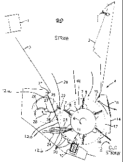
Fig. 1 shows a first embodiment of a straw-cutting
machine with rotating catch plates in a schematic sid~'
view;
Fig. 2 shows a second embodiment with cutters hung in a
floating manner; and
Fig. 3 shows the embodiment of Fig. 1 in a
representation without the arrows indicating the
3o airflow.
4

CA 02272146 2004-09-17
Referring to Figures 1 and 2, under the end of a straw-
walker 1 of a combine harvester, a funnel-shaped inlet
housing 40 for the straw is disposed whose front wall 2 and
rear wall 3 taper off towards the straw-cutting machine
housing 4 and limit the inlet region into the straw-cutting
machine housing 4 covered by the rotor 5. Any suitable
known cutting tools can be used such as catch plates 7,
disposed on the casing of the rotor 5, which rotates in the
direction of the arrow 6. The cutting tools 7 have holding
plates 8 that can be mounted in a fixed position or
rotatable around axes on the rotor jacket 41.
In the outlet region of the straw-cutting machine housing 4,
a cutter bar 10 is disposed in a fixed manner on the housing
i5 in which the counter-cutters 11 interacting with the catch
plates 7 are mounted. The region between the lower end 21 of
the rear wall 3 of the funnel-shaped inlet housing and the
cutter bar 10 is closed by the straw-cutting machine bottom
120, comprising an upper portion, shown as guide plate 12a
2o and a lower portion comprising cutter base 12b, forming a
part of the straw-cutting machine housing 4. Guide plate 12a
and cutter base 12b mutually cooperate and can be integrally
constructed. The straw-cutting machine bottom 120 thus
guides the cut stalks through the cutting process.
In the region of the inlet slit 22 of the straw-cutting
machine, further counter-cutters 23 are provided which are
disposed on a second cutter bar 24. Each of the counter
cutters 11 and 23 can be adjusted, that is moved towards the
3o axis of rotation of the rotor 5 or away from it. The
counter-cutters 11 and 23 protrude into the cutting area 17
5

CA 02272146 2004-09-17
of the cutting tools 7. To make this possible, the cutting
tools or catch plates 7 possess a corresponding slot.
Cutter base 12b possesses in the region between the cutter
bars 24 and 10 step-shaped elevations 20 which work as
accumulation plates and additionally break and eddy the
obstructing ascending air current.
Furthermore, in the straw-cutting machine bottom 120, in the
so region of guide plate 12a between the lower end 21 of the
rear wall 3 and the cutter bar 24, slots 25 are provided
which run in each case in the longitudinal direction and
whose plurality essentially extends over the width of the
rotor. The slots 25 are penetrated by moving tines 26 which
are disposed on a drivable feed roller 27 which is drivable
in the direction of arrow 28 by a suitable drive means (not
shown). As can be seen from Fig. 1, those parts of the
tines 26 which penetrate the slots 25 move towards the rotor
or the counter-cutters 23. They transport the cut stalks in
2o the direction of the arrow 29 into the inlet gap 22 of the
straw-cutting machine. In this way, the curved tines 26 o:E
the drivable feed roller 27 prevent cut stalks from being
able to accumulate in the region of the inlet gap 22.
These cut stalks are further transported from there into the
inlet slit of the straw-cutting machine. The tines 26 are
curved in the direction of rotation 28 in the manner visible
from Fig. 1.
Above the outlet 13 of the straw-cutting machine, a hood 14
3o is disposed which is provided at its upper end with a first
accumulation plate 15 and at its lower end with a second
accumulation plate 16, which are fixed in the manner shown
6

CA 02272146 2004-09-17
on the circuit 17 covered by the cutting tools 7. Tree
accumulation plates 15 and 16 essentially ru.n
perpendicularly to the tangent on the circle 17 swept by the
cutters 7; that is, they essentially point towards the axis
s of rotation of the rotor 5. The accumulation plates 15 and
16 end a very short distance, typically around 5 to 10 mm.,
away from the circle 17. The hood 14 is provided on its
front side with one or more perforations or venting slits 18
through which the air can exit and flow out without problem..
In the embodiment of Fig. 2, instead of the catch plates 7,
flail cutters 30 are used, and which are hung in a floating
manner on axles 31.

Representative Drawing
A single figure which represents the drawing illustrating the invention.
Administrative Status

2024-08-01:As part of the Next Generation Patents (NGP) transition, the Canadian Patents Database (CPD) now contains a more detailed Event History, which replicates the Event Log of our new back-office solution.

Please note that "Inactive:" events refers to events no longer in use in our new back-office solution.

For a clearer understanding of the status of the application/patent presented on this page, the site Disclaimer , as well as the definitions for Patent , Event History , Maintenance Fee  and Payment History  should be consulted.

Event History

Description Date
Inactive: Adhoc Request Documented 2018-06-06
Revocation of Agent Requirements Determined Compliant 2018-05-18
Appointment of Agent Requirements Determined Compliant 2018-05-18
Time Limit for Reversal Expired 2009-05-19
Letter Sent 2008-05-20
Grant by Issuance 2005-08-02
Inactive: Cover page published 2005-08-01
Pre-grant 2005-04-08
Inactive: Final fee received 2005-04-08
Notice of Allowance is Issued 2004-12-23
Letter Sent 2004-12-23
Notice of Allowance is Issued 2004-12-23
Inactive: Approved for allowance (AFA) 2004-11-15
Amendment Received - Voluntary Amendment 2004-09-17
Inactive: S.30(2) Rules - Examiner requisition 2004-03-19
Amendment Received - Voluntary Amendment 2003-12-12
Inactive: S.30(2) Rules - Examiner requisition 2003-06-26
Inactive: Entity size changed 2002-05-10
Amendment Received - Voluntary Amendment 2000-02-11
Inactive: Cover page published 1999-11-28
Application Published (Open to Public Inspection) 1999-11-26
Inactive: Status info is complete as of Log entry date 1999-11-23
Letter Sent 1999-11-23
Inactive: Application prosecuted on TS as of Log entry date 1999-11-23
All Requirements for Examination Determined Compliant 1999-11-02
Request for Examination Requirements Determined Compliant 1999-11-02
Request for Examination Received 1999-11-02
Inactive: IPC assigned 1999-07-02
Inactive: First IPC assigned 1999-07-02
Inactive: Filing certificate - No RFE (English) 1999-06-17
Filing Requirements Determined Compliant 1999-06-17
Application Received - Regular National 1999-06-16

Abandonment History

There is no abandonment history.

Maintenance Fee

The last payment was received on 2005-05-17

Note : If the full payment has not been received on or before the date indicated, a further fee may be required which may be one of the following

  • the reinstatement fee;
  • the late payment fee; or
  • additional fee to reverse deemed expiry.

Please refer to the CIPO Patent Fees web page to see all current fee amounts.

Fee History

Fee Type Anniversary Year Due Date Paid Date
Application fee - small 1999-05-18
Request for examination - small 1999-11-02
MF (application, 2nd anniv.) - small 02 2001-05-18 2001-04-24
MF (application, 3rd anniv.) - standard 03 2002-05-20 2002-04-26
MF (application, 4th anniv.) - standard 04 2003-05-20 2003-05-02
MF (application, 5th anniv.) - standard 05 2004-05-18 2004-05-17
Final fee - standard 2005-04-08
MF (application, 6th anniv.) - standard 06 2005-05-18 2005-05-17
MF (patent, 7th anniv.) - standard 2006-05-18 2006-04-24
MF (patent, 8th anniv.) - standard 2007-05-18 2007-04-16
Owners on Record

Note: Records showing the ownership history in alphabetical order.

Current Owners on Record
FRANZ SCHRATTENECKER
Past Owners on Record
None
Past Owners that do not appear in the "Owners on Record" listing will appear in other documentation within the application.
Documents

To view selected files, please enter reCAPTCHA code :


To view images, click a link in the Document Description column. To download the documents, select one or more checkboxes in the first column and then click the "Download Selected in PDF format (Zip Archive)" or the "Download Selected as Single PDF" button.

List of published and non-published patent-specific documents on the CPD .

If you have any difficulty accessing content, you can call the Client Service Centre at 1-866-997-1936 or send them an e-mail at CIPO Client Service Centre.


Document
Description 
Date
(yyyy-mm-dd) 
Number of pages   Size of Image (KB) 
Representative drawing 1999-11-05 1 10
Cover Page 1999-11-05 1 32
Description 1999-05-18 6 239
Abstract 1999-05-18 1 16
Claims 1999-05-18 1 27
Drawings 1999-05-18 3 61
Description 2003-12-12 6 241
Claims 2003-12-12 2 48
Abstract 2004-09-17 1 13
Description 2004-09-17 7 250
Claims 2004-09-17 2 48
Drawings 2004-09-17 3 48
Representative drawing 2005-07-21 1 10
Cover Page 2005-07-21 1 36
Filing Certificate (English) 1999-06-17 1 165
Acknowledgement of Request for Examination 1999-11-23 1 178
Reminder of maintenance fee due 2001-01-22 1 112
Commissioner's Notice - Application Found Allowable 2004-12-23 1 161
Maintenance Fee Notice 2008-07-02 1 171
Fees 2001-04-24 1 45
Correspondence 2005-04-08 2 45