Language selection

Search

Patent 2272183 Summary

Third-party information liability

Some of the information on this Web page has been provided by external sources. The Government of Canada is not responsible for the accuracy, reliability or currency of the information supplied by external sources. Users wishing to rely upon this information should consult directly with the source of the information. Content provided by external sources is not subject to official languages, privacy and accessibility requirements.

Claims and Abstract availability

Any discrepancies in the text and image of the Claims and Abstract are due to differing posting times. Text of the Claims and Abstract are posted:

  • At the time the application is open to public inspection;
  • At the time of issue of the patent (grant).
(12) Patent Application: (11) CA 2272183
(54) English Title: AUTOMATIC PIPETTING APPARATUS
(54) French Title: APPAREIL AUTOMATIQUE DE PIPETTAGE
Status: Deemed Abandoned and Beyond the Period of Reinstatement - Pending Response to Notice of Disregarded Communication
Bibliographic Data
(51) International Patent Classification (IPC):
  • G01N 35/10 (2006.01)
  • B01L 03/02 (2006.01)
  • G01N 35/04 (2006.01)
(72) Inventors :
  • EIPEL, HEINZ (Germany)
(73) Owners :
  • ABBOTT GMBH & CO. KG
(71) Applicants :
  • ABBOTT GMBH & CO. KG (Germany)
(74) Agent: ROBIC AGENCE PI S.E.C./ROBIC IP AGENCY LP
(74) Associate agent:
(45) Issued:
(22) Filed Date: 1999-05-18
(41) Open to Public Inspection: 1999-11-25
Examination requested: 2004-05-17
Availability of licence: N/A
Dedicated to the Public: N/A
(25) Language of filing: English

Patent Cooperation Treaty (PCT): No

(30) Application Priority Data:
Application No. Country/Territory Date
198 23 283.7 (Germany) 1998-05-25

Abstracts

English Abstract


The invention relates to an automatic pipetting apparatus, having a drive for
moving a pipetting instrument from a source site to a target site, in which
apparatus
end stops (8-10, 14, 15), which can be finely adjusted automatically, for the
movements of the pipetting instrument (1) generated by the drive are provided
at
the source site and/or the target site.


Claims

Note: Claims are shown in the official language in which they were submitted.

5~
We claim:
1. An automatic pipetting apparatus, having a drive for moving a pipetting
instrument (1) from a source site to a target site, wherein end stops (8-10,
14, 15), which can be finely adjusted automatically, for the movements of
the pipetting instrument (1) generated by the drive are provided at the
source site and/or the target site.
2. An automatic pipetting apparatus as claimed in claim 1, wherein
shock-absorbing means are arranged on the end stops (8-10, 14, 15).
3. An automatic pipetting apparatus as claimed in claim 1 or 2, wherein the
drive is designed as a hydraulic or pneumatic linear drive.
4. An automatic pipetting apparatus as claimed in any of claims 1 to 3,
wherein the end stops (8-10, 14, 15) have stop faces which are controlled by
stepper motors.
5. An automatic pipetting apparatus as claimed in any of claims 1 to 4,
wherein sensors (31, 32) for position detection are arranged on the end
stops (8-10, 14, 15).
6. An automatic pipetting apparatus as claimed in any of claims 1 to 5,
wherein the end stops (8, 9) of the source site have a different adjustment
accuracy from the end stops (14, 15) of the target site.
7. A method for automatic pipetting, comprising collection of a substance at a
source site and delivery of the substance at a target site, and the movement
of the pipetting instrument from the source site to the target site, wherein
the pipetting instrument is moved rapidly from the source site, and wherein
end stops, the position of which can be varied, are in the mean time moved
into an accurate position at the target site, the movements being locally
independent of one another.

6
8. A method as claimed in claim 7, wherein the rapid movement is decelerated
before the end stop is reached.
9. A method as claimed in claim 7 or 8, wherein the position of the pipetting
instrument is measured after the end stop has been reached.

Description

Note: Descriptions are shown in the official language in which they were submitted.


CA 02272183 1999-OS-18
" - 1 -
Automatic pipetting apparatus
The invention relates to an automatic pipetting apparatus, having a drive for
moving a pipetting instrument from a source site to a target site, which
apparatus is
used, for example, for mass screening in order to discover new lead structures
in
particular for pharmacology and crop protection.
At the moment, it is generally customary for the substances to be tested to be
presented to an automatic testing apparatus in the Mikrotiter Format (with 96
to
1536 wells per plate). From this presentation arrangement, the substances have
to
be transferred separately to the individual analysis sites using an automatic
pipetting apparatus. Also, as the tests progress, further pipetting steps are
required
although in general these may be carned out together rather than separately
for
each analysis site. The pipetting of individual substances when carrying out
mass
screening tests is particularly time-consuming. Screening with so-called spot
arrays also requires an enormous number of individual pipetting steps.
The automatic pipetting apparatus which are currently customary guide the
pipetting instrument over a work surface with one drive each for the x-, y-
and
generally also the z-axes. According to the prior art, it is possible, in
principle, to
establish various types of drive. For example, one drive used is a stepper
motor
which transmits a linear movement via a recirculating ball screw. The
advantage
of this type of drive is the very high level of accuracy combined with
relatively low
costs. The main drawback is the fact that the linear movement is extremely
slow,
even if a speed ramp with different speeds is passed through during the actual
adjustment operation.
In addition, DC motor drives with a resistive, inductive or capacitive sensor
or with
an optical linear guide are used for position feedback. These drives are
significantly quicker than stepper motors, but are complex and therefore
expensive.
In principle, the same advantages and disadvantages also apply to linear
motors
used as an alternative to rotating motors.

CA 02272183 1999-OS-18
2
The invention relates to an automatic pipetting apparatus which avoids the
drawbacks of previous arrangements while achieving high pipetting speeds.
According to the invention, it is possible to divide the linear movement into
a rapid
movement over a relatively long distance between source site and target site,
end
stops, which can be finely adjusted automatically, being arranged with a high
level
of accuracy at both the source site and the target site. The adjustable end
stops,
which normally only have to be adjusted by a few millimeters or a few hundred
micrometers, combined with the rapid movement result in an enormous increase
in
the transfer rate.
Arranging shock-absorbing means on the end stops decelerates the rapid
movement
before the stop is reached. It is thus possible to avoid impacts.
Preferably, the drive is designed as a hydraulic or pneumatic linear drive and
is
therefore inexpensive when moving rapidly.
In order to feed back information concerning arrival at the end stops, sensors
for
position detection may be arranged in the area of the end stops, which sensors
register the arnval of the pipetting instrument at the end stops and, if
appropriate,
feed this information to a control unit or memory unit. To counteract having
to
wait for the end of the transient mechanical effect caused by the stop, the
speed is
increased again.
Finally, it is possible to use end stops with different adjustment accuracies,
allowing the costs to be reduced further, since hitherto the highest
adjustment
accuracy of one individual direction of movement was decisive for the entire
system.
The invention also relates to a method with which the pipetting speeds are
increased significantly, which is achieved by means of the mutually
independent
adjustment within short distances of the end stop and the relatively long
distances.
In a refinement of the method, the rapid movement is decelerated before the
end
stop is reached, it being possible, furthermore, to measure the position of
the
pipetting instrument after the end stop has been reached and, if appropriate,
to carry
out a correction in the event of positional inaccuracies.

CA 02272183 1999-OS-18
_ 3
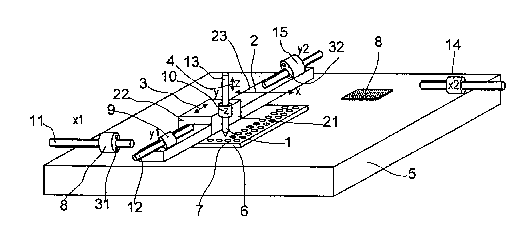
The drawing shows a diagrammatic sketch of an automatic pipetting apparatus
according to the invention.
The automatic pipetting apparatus has a pipetting instrument 1 which can be
moved over a work surface 5 in three axes 2, 3, 4 in the x-, y- and z-
directions.
A substance bank plate 6, which has a plurality of wells 7 for substances, is
arranged on the work surface 5. Furthermore, a specimen slide 8, to which the
substances contained in the plate 6 are to be applied, is arranged on the work
surface S.
At the source site, a well 7 in the plate 6, the pipetting instrument 1 is
brought to
bear against stops 8, 9, 10, it being possible to adjust the end stops 8, 9,
10 via a
spindle drive 11, 12, 13.
At the target site, a point on the specimen slide 8, the pipetting instrument
1 is
again brought to bear against adjustable end stops 14, 15 (x2, ~), the drive
for
actually moving the pipetting instrument not being shown.
The pipetting instrument 1 is attached to a holder 21 which can be displaced
in the
direction of the z-axis. For its part, this holder 21 is arranged on a
carriage 22
which is mounted so that it can be displaced on a bar 23 in the direction of
the y-
axis 3. For its part, the bar 23 is mounted and driven so that it can be moved
in the
direction of the x-axis 2, in a manner which is not shown.
In order to overcome the problems presented by the long distances, the drive
(not
shown) used is a hydraulic or pneumatic drive, in which case the drive
elements
may be simple cylinders with pistons. An advantage of this solution is the low
mass and robustness of the drive element, with the result that the movements
can
be carried out particularly quickly. Although in principle the adjustable end
stops
allow position feedback to be dispensed with, sensors 31, 32 for confirming
that
the carnage 22 or the bar 23 is bearing against the end stops are provided in
the end
stops 8, 15, in order to avoid a pipetting instrument which is not yet in the
final
position from delivering or collecting substances incorrectly.

CA 02272183 1999-OS-18
- 4
The arrangement of accurate end stops 8 to 10, 14, 15, which can be moved by
stepper motors, both at the source site and at the target site, and for each
of the
individual axes 2, 3, 4, results in a substantial increase in the pipetting
rates, since
the end stops only have to undergo minimal adjustment between the individual
pipetting operations. The relatively long distances between source site and
target
site can be covered by means of an electric, hydraulic or preferably pneumatic
drive.
Furthermore, a hydraulic or pneumatic damping cylinder, which decelerates the
rapid movement just as the respective preset stop is reached and prevents
impacts,
may be arranged on the end stops. This is not shown in the drawing.
The principal application is a "reformatting" of analyses which are to be
carried out
in parallel from microtiter plate format to a nano-format with a few thousand
analysis points, e.g. on a specimen slide which is customarily used in
microscopy.
The end stops xl and yl, which are, for example, driven by stepper motors, fix
the
sites of the wells 7 of the microtiter plate 6, which is regarded as the
source for the
substances which are to be pipetted. The fine-resolution end stops x2 and ~l
determine the target sites on the specimen slide. In this case, the resolution
accuracy of the end stops in question may be a function of the positional
accuracy
required. For example, a lower level of accuracy can be set for the approach
to the
relatively low (grid) resolution wells at the source site than at the high-
resolution
analysis points on the specimen slide at the target site. This feature is
particularly
advantageous compared to systems known hitherto.

Representative Drawing
A single figure which represents the drawing illustrating the invention.
Administrative Status

2024-08-01:As part of the Next Generation Patents (NGP) transition, the Canadian Patents Database (CPD) now contains a more detailed Event History, which replicates the Event Log of our new back-office solution.

Please note that "Inactive:" events refers to events no longer in use in our new back-office solution.

For a clearer understanding of the status of the application/patent presented on this page, the site Disclaimer , as well as the definitions for Patent , Event History , Maintenance Fee  and Payment History  should be consulted.

Event History

Description Date
Application Not Reinstated by Deadline 2007-05-18
Time Limit for Reversal Expired 2007-05-18
Deemed Abandoned - Failure to Respond to Maintenance Fee Notice 2006-05-18
Inactive: IPC from MCD 2006-03-12
Letter Sent 2004-05-28
Request for Examination Received 2004-05-17
All Requirements for Examination Determined Compliant 2004-05-17
Request for Examination Requirements Determined Compliant 2004-05-17
Letter Sent 2003-04-07
Application Published (Open to Public Inspection) 1999-11-25
Inactive: Cover page published 1999-11-24
Inactive: First IPC assigned 1999-07-20
Letter Sent 1999-06-17
Inactive: Filing certificate - No RFE (English) 1999-06-17
Application Received - Regular National 1999-06-16

Abandonment History

Abandonment Date Reason Reinstatement Date
2006-05-18

Maintenance Fee

The last payment was received on 2005-03-29

Note : If the full payment has not been received on or before the date indicated, a further fee may be required which may be one of the following

  • the reinstatement fee;
  • the late payment fee; or
  • additional fee to reverse deemed expiry.

Patent fees are adjusted on the 1st of January every year. The amounts above are the current amounts if received by December 31 of the current year.
Please refer to the CIPO Patent Fees web page to see all current fee amounts.

Fee History

Fee Type Anniversary Year Due Date Paid Date
Registration of a document 1999-05-18
Application fee - standard 1999-05-18
MF (application, 2nd anniv.) - standard 02 2001-05-18 2001-04-24
MF (application, 3rd anniv.) - standard 03 2002-05-20 2002-04-02
Registration of a document 2003-02-19
MF (application, 4th anniv.) - standard 04 2003-05-19 2003-04-03
MF (application, 5th anniv.) - standard 05 2004-05-18 2004-03-24
Request for examination - standard 2004-05-17
MF (application, 6th anniv.) - standard 06 2005-05-18 2005-03-29
Owners on Record

Note: Records showing the ownership history in alphabetical order.

Current Owners on Record
ABBOTT GMBH & CO. KG
Past Owners on Record
HEINZ EIPEL
Past Owners that do not appear in the "Owners on Record" listing will appear in other documentation within the application.
Documents

To view selected files, please enter reCAPTCHA code :


To view images, click a link in the Document Description column (Temporarily unavailable). To download the documents, select one or more checkboxes in the first column and then click the "Download Selected in PDF format (Zip Archive)" or the "Download Selected as Single PDF" button.

List of published and non-published patent-specific documents on the CPD .

If you have any difficulty accessing content, you can call the Client Service Centre at 1-866-997-1936 or send them an e-mail at CIPO Client Service Centre.

({010=All Documents, 020=As Filed, 030=As Open to Public Inspection, 040=At Issuance, 050=Examination, 060=Incoming Correspondence, 070=Miscellaneous, 080=Outgoing Correspondence, 090=Payment})


Document
Description 
Date
(yyyy-mm-dd) 
Number of pages   Size of Image (KB) 
Representative drawing 1999-11-04 1 10
Abstract 1999-05-17 1 12
Description 1999-05-17 4 193
Claims 1999-05-17 2 48
Drawings 1999-05-17 1 12
Courtesy - Certificate of registration (related document(s)) 1999-06-16 1 116
Filing Certificate (English) 1999-06-16 1 165
Reminder of maintenance fee due 2001-01-21 1 112
Reminder - Request for Examination 2004-01-19 1 113
Acknowledgement of Request for Examination 2004-05-27 1 176
Courtesy - Abandonment Letter (Maintenance Fee) 2006-07-12 1 175