Language selection

Search

Patent 2272428 Summary

Third-party information liability

Some of the information on this Web page has been provided by external sources. The Government of Canada is not responsible for the accuracy, reliability or currency of the information supplied by external sources. Users wishing to rely upon this information should consult directly with the source of the information. Content provided by external sources is not subject to official languages, privacy and accessibility requirements.

Claims and Abstract availability

Any discrepancies in the text and image of the Claims and Abstract are due to differing posting times. Text of the Claims and Abstract are posted:

  • At the time the application is open to public inspection;
  • At the time of issue of the patent (grant).
(12) Patent: (11) CA 2272428
(54) English Title: SECONDARY BATTERY
(54) French Title: ACCUMULATEUR ELECTRIQUE
Status: Term Expired - Post Grant Beyond Limit
Bibliographic Data
(51) International Patent Classification (IPC):
  • H01M 10/00 (2006.01)
(72) Inventors :
  • PARK, UN SICK (Republic of Korea)
  • SONG, YOUNG BAE (Republic of Korea)
(73) Owners :
  • SAMSUNG DISPLAY DEVICES CO. LTD.
(71) Applicants :
  • SAMSUNG DISPLAY DEVICES CO. LTD. (Republic of Korea)
(74) Agent: MOFFAT & CO.
(74) Associate agent:
(45) Issued: 2007-01-09
(86) PCT Filing Date: 1998-04-06
(87) Open to Public Inspection: 1999-06-03
Examination requested: 2002-11-28
Availability of licence: N/A
Dedicated to the Public: N/A
(25) Language of filing: English

Patent Cooperation Treaty (PCT): Yes
(86) PCT Filing Number: PCT/KR1998/000082
(87) International Publication Number: KR1998000082
(85) National Entry: 1999-05-18

(30) Application Priority Data:
Application No. Country/Territory Date
97-62414 (Republic of Korea) 1997-11-24

Abstracts

English Abstract


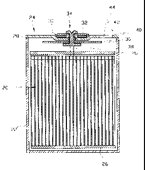
A secondary battery comprises a can into which an electrode
assembly is inserted, a cap assembly mounted to an opening of the can; and
an electrolyte injection hole formed on at least one of the can and cap
assembly, and a safety member to close the electrolyte injection hole. The
electrolyte injection hole is formed on a negative portion of the cap
assembly. The safety member is inserted into and welded on the
electrolyte injection hole.


French Abstract

Accumulateur électrique composé d'un récipient métallique dans lequel est introduit un ensemble électrode, d'un ensemble couvercle monté sur une ouverture du récipient métallique et d'un orifice d'injection d'électrolyte situé sur au moins un du récipient métallique et de l'ensemble couvercle, ainsi que d'un élément de sécurité servant à fermer ledit orifice. Cet orifice est placé sur une partie négative de l'ensemble couvercle. L'élément de sécurité est introduit dans l'orifice d'injection d'électrolyte et soudé à ce dernier.

Claims

Note: Claims are shown in the official language in which they were submitted.


What is claimed is:
1. ~A secondary battery comprising a can and a cap assembly, and further
comprising:
an electrolyte injection hole formed on at least one of the can and the cap
assembly; and
a safety member to close the electrolyte injection hole, the safety member
breakable for reducing an internal pressure in the can once the internal
pressure
exceeds a predetermined level.
2. ~A secondary battery of claim 1, wherein the electrolyte injection hole is
formed on a negative electrode portion of the cap assembly.
3. ~A secondary battery of claim 1, wherein the safety member is inserted into
and welded on the electrolyte injection hole.
4. ~A secondary battery of claim 2, wherein the safety member is disposed on
the electrolyte injection hole and is welded on the negative electrode portion
thereof.
5. ~A secondary battery of claim 1, wherein the safety member is made of a
material selected from the group consisting of aluminum, nickel. stainless
steel, and
nickel gilding steel plate.
6. ~A secondary battery of claim 1, wherein the safety member is designed to
be broken by battery pressure of about 10-30 kgf/cm2.
7. ~A secondary battery of claim 2, wherein the safety member is provided with
a plurality of grooves.
7

8. A secondary battery of claim 7, wherein the safety member is inserted into
and welded on the electrolyte injection hole.
9. A secondary battery of claim 7, wherein the safety member is disposed on
the electrolyte injection hole and is welded on the negative electrode portion
thereof.
10. A secondary battery of claim 7, wherein the safety member is made of a
material selected from the group consisting of aluminum, nickel, stainless
steel and
nickel gilding steel plate.
11. A secondary battery of claim 7, wherein the safety member is designed to
be broken by battery pressure of about 10-30 kgf/cm2.
8

Description

Note: Descriptions are shown in the official language in which they were submitted.


CA 02272428 1999-OS-18
SECONDARY BATTERY
TECHNICAL FIELD
The present invention relates to a secondary battery and, more
particularly, a safety system of a secondary battery which can reduce
internal pressure thereof to prevent the explosion of the secondary battery.
BACKGROUND ART
Generally, a secondary battery is a rechargeable battery such as a
1 o nickel-metal hydride battery, a lithium battery or a lithium-ion battery
which is widely used in many applications. Such a secondary battery is
subject to high internal pressures due to gases generated by chemical
reactions when it is discharged and recharged. Though not common, it is
possible for the battery to explode as a result of the gases produced.
Therefore, many presently known secondary batteries have a cap
assembly provided with a safety valve which can discharge gases through a
discharge hole formed on a cap cover so as to reduce the pressure in the
batteries when the pressure in the battery is excessively raised.
The lithium-ion battery comprises an electrode assembly inserted
2o into a cap. A cap assembly is mounted on an upper end of the can.
Electrolyte is injected into the can through an inlet port formed on the cap
assembly. Insulating members are disposed between the electrode
assembly and the can.
Referring to Fig. 3, there is shown a conventional cap assembly 2.
The cap assembly 2 comprises a negative portion 4 welded on an upper end
of the can, a positive portion 6 disposed on a central portion of the negative
portion 4, and an insulating plate 8 disposed between the negative portion 4
and positive portion 6. A rivet 10 penetrates through the negative potion 4
and positive portion 6 is coupled to the positive electrode of the roll
3o electrode assembly.
In the above described conventional lithium-ion battery, if the
1

CA 02272428 2005-10-28
pressure within the battery is abruptly increased by the gas generated
therein, the
battery may explode. Thus, there is provided gas release means in the
secondary
battery.
'That is, safety grooves 12 are formed in the negative portion 4 of the cap
assembly 2 through a mechanical process, etching or electrofoaming process.
The
safety grooves 12 are broken open when the internal pressure of the battery is
increased above a predetermined level, thereby preventing the batter's I-rom
exploding.
An electrolyte injection hole 14 is formed on the negative portion 4 of the
cap assembly 2. After the electrolyte is injected through the hole 14, a plug
16 is
snugly f tted into the hole 14 and is then welded to provide a seal.
FIG. 4 shows another example of a conventional cap assembly 2.
In this example, a ball(not shown) is inserted into the injection hole 18 and
is then welded to provide a seal.
In the above described conventional cap assembly shown in FIGS. 3 and 4,
since the safety grooves and the electrolyte injection hole are formed on the
negative portion which is small in size, it is difficult to design and
manufacture the
same.
In the conventional cap assembly shown in FIG. 4, since the diameter of the
injection hole is small, it is difficult to inject electrolyte into the can.
DISCLOSURE OF INVENTION
Therefore, the present invention has been made in an effort to solve the
above described drawbacks of the prior art.
It is an object of the present invention to provide a cap assembly for a
secondary battery, in which safety means can precisely operate at a pre-set
pressure
to prevent the battery from exploding.
It is another object of the present invention to provide a cap assembly in
which the safety means can be easily formed, thereby reducing
2

CA 02272428 2005-10-28
manufacturing costs.
To achieve the above objects, the present invention provides a secondary
battery comprising a can and a cap assembly, and further comprising: an
electrolyte
injection hole formed on at least one of the can and the cap assembly; and a
safety
member breakable by a predetermined battery pressure to close the electrolyte
injection hole.
Preferably, the electrolyte injection hole is formed on a negative portion of
the cap assembly.
Preferably, the safety member is inserted into and welded on the electrolyte
injection hole.
Alternatively, the safety member is disposed on the electrolyte injection hole
and is welded on the negative portion.
Preferably, the safety member is made of a material selected from the group
consisting of aluminum, nickel, stainless steel, and nickel gilding steel
plate.
Preferably, the safety member is designed to be broken by battery pressure
of about 10-30 kgf/cm2.
Alternatively, the safety member is provided with a plurality of grooves.
BRIEF DESCRIPTION OF DRAWINGS
The present invention will become more fully understood from the detailed
description given hereinbelow and the accompanying drawings which are given by
way of illustration only, and thus are not limitative of present invention and
wherein:
I~ IG. 1 is a cross sectional view illustrating a secondary battery where a
cap
assembly according to a preferred embodiment of the present invention is
employed;
FIG. 2 is a plane view illustrating a cap assembly of a secondary battery
according to a preferred embodiment of the present invention;
FIG. 3 is a plane view illustrating a conventional cap assembly ol~ a
3

CA 02272428 1999-OS-18
secondary battery; and
Fig. 4 is a plane view illustrating another conventional cap assembly
of a secondary battery.
BEST MODE FOR CARRYING OUT THE INVENTION
The following is the description of the preferred embodiments
according to the present invention. In the drawing, like reference
numerals have been used to identify like elements in each figure.
Referring first to Figs. 1 and 2, there are respectively shown a
sectional view of a secondary battery where a cap assembly 24 according to
the present invention is employed and a plane view of the cap assembly 24.
The cap assembly 24 of the present invention is coupled on an upper
end of a can 22 in which a roll electrode assembly 20 consisting of a
positive electrode, a negative electrode, and a separator, and electrolyte are
~5 received. The can 22 contacts the negative electrode by a tap (not shown).
Insulating plates 26 are provided at upper and lower ends of the
electrode assembly 20 to prevent the electrode assembly 20 from contacting
the cap assembly 24 and the can 22.
The cap assembly 24 comprises a negative portion 28 which is
2o welded to the upper end of the can 22, a positive portion 32 fomned on a
central portion of the negative portion 28, and a rivet 34 mounted
penetrating a central portion of the negative portion 28 and positive portion
32. An insulating member 30 is disposed between the negative portion 28
and positive portion 32. The rivet 34 is used as coupling means for
25 coupling the positive portion 32 with the negative portion 28. An
insulating member 36 is disposed between the rivet 34 and the negative
portion 28. The rivet 34 is connected to the positive electrode of the
electrode assembly through a tap 38. That is, the rivet is used as a
terminal for connecting the positive electrode to the positive portion 32.
3o An electrolyte injection hole 40 is formed on the negative portion 28 to
inject electrolyte into the can.
4

CA 02272428 2005-10-28
Although, in this embodiment, an electrolyte injection hole 40 is formed on
the
negative portion 28, the location of the electrolyte injection hole 40 is not
limited
to this structure but can be formed on the can 22.
After the electrolyte is injected into the can 22, the injection hole 40 is
tightly closed by a safety plate 42. In this embodiment, the safety plate 42
tray be
formed having the same size as that of the injection hole and inserted into
and
welded on the injection hole 40.
Alternatively, the safety plate 42 may be formed having the larger size as
that
of the injection hole 40 and is positioned to cover the injection hole 40.
~I~he safety
plate 42 positioned on the injection hole 40 is welded on the negative portion
28.
rfhe safety plate 42 is for preventing the explosion ofthe battery. That is,
The
safety plate 42 is formed having the thickness or rigidity less than that of
the
negative portion 28.
Alternatively, in the case where the safety plate 42 is made in the same
material as the negative portion 28, safety grooves 44 are formed on the
safety plate
42 through a mechanical process, etching or electrofoaming process. The safety
plate 42 are broken open when the internal pressure of the battery is
increased
above a predetermined level, thereby preventing the battery from exploding.
More in detail, the safety plate 42 may be made of a material selected from
the group consisting of aluminum, nickel, stainless steel, and nickel gilding
steel
plate.
Preferably, the safety plate 42 is designed to be broken by the internal
pressure of about 10-30 kgf/cmZ.
Therefore, when the internal pressure of the battery is increased above a
predetermined level by gas generated when the battery is charged and
discharged,
the safety plate 42 is removed or cracked, thereby enabling gas from the
battery to
be exhausted to reduce the internal pressure.
While this invention has been described in connection with what is presently
considered to be the most practical and preferred embodiments, it
5

CA 02272428 1999-OS-18
is to understood that the invention is not limited to the disclosed
embodiment, but, on the contrary is intended to cover various modifications
and equivalent arrangements and methods included within the spirit and
scope of the appended claims.
10
20
30
6

Representative Drawing
A single figure which represents the drawing illustrating the invention.
Administrative Status

2024-08-01:As part of the Next Generation Patents (NGP) transition, the Canadian Patents Database (CPD) now contains a more detailed Event History, which replicates the Event Log of our new back-office solution.

Please note that "Inactive:" events refers to events no longer in use in our new back-office solution.

For a clearer understanding of the status of the application/patent presented on this page, the site Disclaimer , as well as the definitions for Patent , Event History , Maintenance Fee  and Payment History  should be consulted.

Event History

Description Date
Inactive: Expired (new Act pat) 2018-04-06
Grant by Issuance 2007-01-09
Inactive: Cover page published 2007-01-08
Inactive: Final fee received 2006-11-02
Pre-grant 2006-11-02
Notice of Allowance is Issued 2006-09-21
Letter Sent 2006-09-21
Notice of Allowance is Issued 2006-09-21
Inactive: Approved for allowance (AFA) 2006-09-12
Amendment Received - Voluntary Amendment 2006-07-24
Inactive: S.30(2) Rules - Examiner requisition 2006-01-26
Amendment Received - Voluntary Amendment 2005-10-28
Inactive: S.30(2) Rules - Examiner requisition 2005-04-28
Letter Sent 2002-12-18
Request for Examination Requirements Determined Compliant 2002-11-28
All Requirements for Examination Determined Compliant 2002-11-28
Request for Examination Received 2002-11-28
Letter Sent 1999-08-18
Inactive: Cover page published 1999-08-11
Inactive: Single transfer 1999-07-15
Inactive: IPC assigned 1999-07-14
Inactive: First IPC assigned 1999-07-14
Inactive: Courtesy letter - Evidence 1999-06-29
Inactive: Notice - National entry - No RFE 1999-06-23
Application Received - PCT 1999-06-18
Application Published (Open to Public Inspection) 1999-06-03

Abandonment History

There is no abandonment history.

Maintenance Fee

The last payment was received on 2006-02-13

Note : If the full payment has not been received on or before the date indicated, a further fee may be required which may be one of the following

  • the reinstatement fee;
  • the late payment fee; or
  • additional fee to reverse deemed expiry.

Patent fees are adjusted on the 1st of January every year. The amounts above are the current amounts if received by December 31 of the current year.
Please refer to the CIPO Patent Fees web page to see all current fee amounts.

Owners on Record

Note: Records showing the ownership history in alphabetical order.

Current Owners on Record
SAMSUNG DISPLAY DEVICES CO. LTD.
Past Owners on Record
UN SICK PARK
YOUNG BAE SONG
Past Owners that do not appear in the "Owners on Record" listing will appear in other documentation within the application.
Documents

To view selected files, please enter reCAPTCHA code :


To view images, click a link in the Document Description column. To download the documents, select one or more checkboxes in the first column and then click the "Download Selected in PDF format (Zip Archive)" or the "Download Selected as Single PDF" button.

List of published and non-published patent-specific documents on the CPD .

If you have any difficulty accessing content, you can call the Client Service Centre at 1-866-997-1936 or send them an e-mail at CIPO Client Service Centre.


Document
Description 
Date
(yyyy-mm-dd) 
Number of pages   Size of Image (KB) 
Representative drawing 1999-08-10 1 19
Abstract 1999-05-17 1 13
Description 1999-05-17 6 237
Drawings 1999-05-17 3 73
Claims 1999-05-17 2 42
Claims 2005-10-27 2 44
Drawings 2005-10-27 3 73
Description 2005-10-27 6 233
Claims 2006-07-23 2 46
Abstract 2006-09-20 1 13
Representative drawing 2007-01-02 1 35
Notice of National Entry 1999-06-22 1 194
Courtesy - Certificate of registration (related document(s)) 1999-08-17 1 139
Reminder of maintenance fee due 1999-12-06 1 111
Reminder - Request for Examination 2002-12-08 1 113
Acknowledgement of Request for Examination 2002-12-17 1 174
Commissioner's Notice - Application Found Allowable 2006-09-20 1 161
PCT 1999-05-17 4 190
Correspondence 1999-06-24 1 30
Fees 2003-02-24 1 35
Fees 2000-03-13 1 37
Fees 2002-03-10 1 38
Fees 2001-02-13 1 34
Fees 2004-02-09 1 37
Fees 2005-01-27 1 33
Fees 2006-02-12 1 37
Correspondence 2006-11-01 1 43
Fees 2007-03-07 1 58
Fees 2010-03-24 1 32
Fees 2014-03-30 1 23