Language selection

Search

Patent 2272760 Summary

Third-party information liability

Some of the information on this Web page has been provided by external sources. The Government of Canada is not responsible for the accuracy, reliability or currency of the information supplied by external sources. Users wishing to rely upon this information should consult directly with the source of the information. Content provided by external sources is not subject to official languages, privacy and accessibility requirements.

Claims and Abstract availability

Any discrepancies in the text and image of the Claims and Abstract are due to differing posting times. Text of the Claims and Abstract are posted:

  • At the time the application is open to public inspection;
  • At the time of issue of the patent (grant).
(12) Patent Application: (11) CA 2272760
(54) English Title: SOCKET FOR AN ORNAMENTAL LIGHT BULB
(54) French Title: DOUILLE POUR AMPOULE ELECTRIQUE DECORATIVES
Status: Deemed Abandoned and Beyond the Period of Reinstatement - Pending Response to Notice of Disregarded Communication
Bibliographic Data
(51) International Patent Classification (IPC):
  • H01R 33/05 (2006.01)
  • F21V 19/00 (2006.01)
  • F21V 21/088 (2006.01)
  • H01R 33/09 (2006.01)
(72) Inventors :
  • TSENG, JEOU-NAN (Taiwan, Province of China)
(73) Owners :
  • JEOU-NAN TSENG
(71) Applicants :
  • JEOU-NAN TSENG (Taiwan, Province of China)
(74) Agent: ADE & COMPANY
(74) Associate agent:
(45) Issued:
(22) Filed Date: 1999-05-20
(41) Open to Public Inspection: 2000-11-20
Examination requested: 1999-05-20
Availability of licence: N/A
Dedicated to the Public: N/A
(25) Language of filing: English

Patent Cooperation Treaty (PCT): No

(30) Application Priority Data: None

Abstracts

English Abstract


A socket for an ornamental light bulb is disclosed. The socket has at least
one clasp and at least one sleeve detachable connected with the arms of the
clasp.
Each arm of the clasps has a barb formed on a distal end thereof and the
sleeve
has two stepped faces formed on opposite inside faces thereof to be detachably
connected with the arms of the clasps. Furthermore, a slot is defined between
the
arms of the clasps and a cutout is defined in the sleeve to correspond to the
slot,
such that after the arms of the clasp are connected with the sleeve, the
cutout and
the slot define a circular space therebetween so as to securely hold an
elongate
object therein.


Claims

Note: Claims are shown in the official language in which they were submitted.

-4-
THE EMBODIMENT OF THE INVENTION IN WHICH AN
EXCLUSIVE PROPERTY OR PRIVILEGE IS CLAIMED ARE
DEFINED AS FOLLOWS:
1. A socket for an ornamental light bulb, the socket comprising:
at least one clasp (16) formed with parallel arms; and
at least one sleeve (18) detachably connected with the clasp (16).
2. The socket as claimed in claim 1, wherein a barb (162) is formed on the
distal end of each arm of the clasp (16) and a slot (164) is defined between
the
arms of the clasp (16).
3. The socket as claimed in claim 2, wherein the sleeve (18) has a centrally
formed baffle (182) and two through holes (184) defined to allow the clasps
(16)
to extend through
4. The socket as claimed in claim 3, wherein a cutout (188) defined in a side
face of the sleeve (18) corresponds to the slot (164).
5. The socket as claimed in claim 2, wherein two stepped faces (185) are
respectively in opposite inside faces of the sleeve (18) to mate with the
barbs
(162) on the arms of the clasps (16).
6. The socket as claimed in claim 5, wherein the baffle (182) has two
inclined faces (183) formed in side faces for smoothly guiding the arms of the
clasps (16) of the socket (12).
7. The socket as claimed in claim 5, wherein the sleeve (18) has two slanted
faces (186) respectively formed on opposite inside faces thereof so as to
guide
the arms of the clasps (16) through the through holes (164).
8. The socket as claimed in claim 1, wherein the socket (12) has two clasps
(16) formed in an offset configuration.
9. The socket as claimed in claim 1, wherein the socket (12) has two clasps
(16) formed in alignment with each other.

Description

Note: Descriptions are shown in the official language in which they were submitted.


CA 02272760 1999-OS-20
1 SOCKET FOR AN ORNAMENTAL LIGHT BULB
2 BACK RO IND OF TH . .NTION
3 1. Field of the Invention
4 The present invention relates to a socket for an ornamental light bulb and
more particularly to a socket which is able to receive a light bulb therein as
well
6 as attachto an object. The socket has at least one clasp formed thereon and
a
7 sleeve detachably connected with the clasp. Therefore, before the sleeve is
8 connected with the clasp, an elongate or belt-like object is able to be
threaded
9 through the clasp. Thus, after the clasp is connected with the sleeve, the
socket is
then securely attached to the object.
11 2. Description of Related Art
12 Ornamental light bulbs have been used in various purposes, for example,
13 amusement, decorations or indicators. Most ornamental light bulbs are
equipped
14 with a socket and a bulb detachably inserted into the socket. The wire
providing
1 S power to the bulb is then electrically connected with the bulb and extends
16 outward. People will then use the wire to wind around a tree, a fence or
any other
17 object. However, if the object the ornamental light bulb is going to be
wound
18 around is not elongate but has a net-like structure, such as a net, the
conventional
19 ornamental light bulb will not be able to be attached.
Therefore, a requirement exists to improve the structure of the ornamental
21 light bulb to enhance its connection with objects other than those with an
22 elongated shape.
23 The invention tends to provide a socket for an ornamental light bulb to
24 mitigate and/or obviate the aforementioned problems.
SUMMARY OF THE INVENTION
26 The object of the present invention is to provide a socket for an
ornamental
27 light bulb. The socket enables the light bulb to be fixed on an object
without any
28 auxiliary assistance.
29 Other objectives, advantages, and novel features of the invention will

CA 02272760 1999-OS-20
- 2 -
1 become more apparent from the following detailed description when read in
2 conjunction with the accompanying drawings.
3 B T .F D .~ 1PTION OF TH . D AWTNC'rS
4 Fig. 1 is a perspective view of a socket for an ornamental light bulb in
accordance with the present invention;
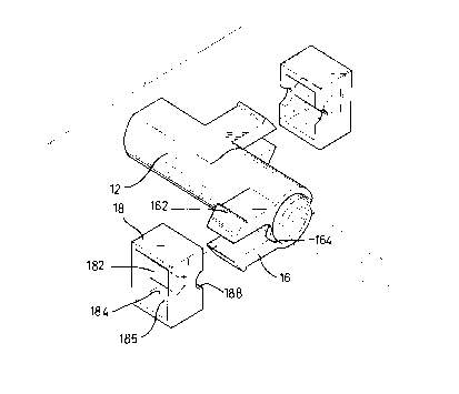
6 Fig. 2 is an exploded perspective view showing the structure of the socket
in
7 Fig. 1;
8 Fig. 3 is a cross sectional view showing the engagement between the tubular
9 socket and the sleeves of the socket in Fig. l; and
Fig. 4 is a perspective view showing alternative embodiment of the socket in
11 accordance with present invention.
12 DETAILED DESCIZTPTION OF TH . P RFRRRFT~ RMROT~TMF.NT
13 As shown in Figs. 1 and 2, a socket (12) for an ornamental light bulb (10)
14 constructed in accordance with the present invention is tubular in shape
and has a
bulb ( 14) inserted in one end thereof. The electrical wires (not shown)
extend out
16 from the other end of the socket ( 12). The socket further has twoclasp (
16)
17 formed thereon in an offset configuration, and each arm of each clasp ( 16)
has a
18 barb ( 162) formed on the distal end thereof. Each clasp ( 16) has a slot (
164)
19 defined between the arms. The socket ( 12) further has a sleeve ( 18)
detachably
connected with each of the clasps ( 16). Each sleeve ( 18) has a centrally
formed
21 baffle ( 182), two through holes ( 184) respectively defined between the
baffle
22 (182) and an inside face of the sleeve (18), two stepped faces (185)
respectively
23 formed on opposite inside faces thereof and two semi-circular cutouts (188)
24 respectively corresponding to one of the slot ( 164). The baffle ( 182) has
a rear
truncated end such that inclined faces (183) are formed on both sides thereof.
26 However, for the purpose of smooth insertion onto the clasps ( 16), two
slanted
27 faces ( 186) are respectively formed on the opposite inside faces of the
sleeve ( 18)
28 nearest to the socket ( 12).
29 By virtue of the slanted faces ( 186) and the inclined faces ( 183 ) of the
sleeve

CA 02272760 1999-OS-20
- 3 -
1 (18), the arms of the clasps (16) are able to be smoothly inserted into the
two
2 through holes ( 184) with the hooks ( 162) detachably connected with the
stepped
3 faces ( 185) of the sleeve ( 18). After the arms of the clasp ( 16) are
inserted into
4 the through holes ( 184) of the sleeve ( 18), the slot ( 164) and the
corresponding
cutout ( 188) form a circular space therebetween, as shown in Fig. 3.
6 When the circular space is formed by the slot ( 164) and the cutout ( 188),
an
7 elongate object (19) such as thread or belt or a web-like object can be
received
8 therein. That is, before the sleeves ( 18) are inserted onto the clasps (
16) , the
9 object ( 19) is first placed in either the slot ( 164) or the cutout ( 188).
Then, after
the clasps ( 16) are connected with the sleeve ( 18), the object ( 19) is
securely held
11 between the slot (164) and the cutout (188).
12 Referring to Figs. 1 and 4, it is noted that the two clasps (16) are formed
13 either in an offset configuration on the socket ( 12) or aligned. From the
14 description above, the present invention has the following advantages:
1. Easy assembly
16 Due to the horizontally formed clasps ( 16), the slanted faces ( 186) and
the
17 inclined faces ( 183), the insertion of the clasps ( 16) into the through
holes ( 184)
18 is smooth and easy.
19 2. Practical function
By means of the formation of the circular space between the slot ( 164) and
21 the cutout (188), an elongate object (19) or a web-like object is able to
be
22 securely held therebetween.
23 3. Low cost
24 Because both the socket ( 12) and the sleeve ( 18) can be formed by
injection
molding, the cost thereof is kept low.
26 Although the present invention has been explained in relation to its
27 preferred embodiment, it is to be understood that many other possible
28 modifications and variations can be made without departing from the spirit
and
29 scope of the invention as hereinafter claimed.

Representative Drawing
A single figure which represents the drawing illustrating the invention.
Administrative Status

2024-08-01:As part of the Next Generation Patents (NGP) transition, the Canadian Patents Database (CPD) now contains a more detailed Event History, which replicates the Event Log of our new back-office solution.

Please note that "Inactive:" events refers to events no longer in use in our new back-office solution.

For a clearer understanding of the status of the application/patent presented on this page, the site Disclaimer , as well as the definitions for Patent , Event History , Maintenance Fee  and Payment History  should be consulted.

Event History

Description Date
Inactive: IPC expired 2016-01-01
Inactive: IPC from MCD 2006-03-12
Time Limit for Reversal Expired 2002-05-21
Application Not Reinstated by Deadline 2002-05-21
Deemed Abandoned - Failure to Respond to Maintenance Fee Notice 2001-05-22
Application Published (Open to Public Inspection) 2000-11-20
Inactive: Cover page published 2000-11-19
Inactive: First IPC assigned 1999-07-21
Filing Requirements Determined Compliant 1999-06-30
Inactive: Filing certificate - RFE (English) 1999-06-30
Application Received - Regular National 1999-06-23
Request for Examination Requirements Determined Compliant 1999-05-20
All Requirements for Examination Determined Compliant 1999-05-20

Abandonment History

Abandonment Date Reason Reinstatement Date
2001-05-22

Fee History

Fee Type Anniversary Year Due Date Paid Date
Request for examination - small 1999-05-20
Application fee - small 1999-05-20
Owners on Record

Note: Records showing the ownership history in alphabetical order.

Current Owners on Record
JEOU-NAN TSENG
Past Owners on Record
None
Past Owners that do not appear in the "Owners on Record" listing will appear in other documentation within the application.
Documents

To view selected files, please enter reCAPTCHA code :


To view images, click a link in the Document Description column. To download the documents, select one or more checkboxes in the first column and then click the "Download Selected in PDF format (Zip Archive)" or the "Download Selected as Single PDF" button.

List of published and non-published patent-specific documents on the CPD .

If you have any difficulty accessing content, you can call the Client Service Centre at 1-866-997-1936 or send them an e-mail at CIPO Client Service Centre.


Document
Description 
Date
(yyyy-mm-dd) 
Number of pages   Size of Image (KB) 
Claims 1999-05-20 1 43
Drawings 1999-05-20 4 76
Description 1999-05-20 3 148
Abstract 1999-05-20 1 22
Cover Page 2000-11-15 1 35
Representative drawing 2000-11-15 1 11
Filing Certificate (English) 1999-06-30 1 165
Reminder of maintenance fee due 2001-01-23 1 112
Courtesy - Abandonment Letter (Maintenance Fee) 2001-06-19 1 182