Note: Descriptions are shown in the official language in which they were submitted.
CA 02272818 1999-OS-26
Exhaust gas extraction apparatus for a vehicle shed
This invention relates an exhaust gas extraction apparatus for a vehicle shed,
with a running rail arranged in the exit direction of the vehicle in the upper
shed region,
s a carriage which can travel thereon, an extraction hose hanging down from
the carnage,
with an extraction socket disposed at its lower, free end and capable of being
clamped
on to the exhaust, and a connecting hose which can extend elastically in its
longitudinal
direction, which is connected at one end to the carriage and at the other end
to a
collecting line or the like and which is carried from the running rail by
means of a
1o plurality of supports with rollers which can move in the running rail.
In one such known exhaust gas extraction apparatus (cf. Brochure of the
Company Blaschke GmbH, D-86405 Meitingen, "'Air Track' Abgas-Absaug-System ")
the carriage can move freely. The known exhaust gas extraction apparatus
serves to
extract exhaust gases from commercial vehicles in operational and parking
sheds in fire
1s stations, ambulance stations and other operational areas. When the vehicle
is stationary
the extraction hose is clamped on to the exhaust of the vehicle by means of
the
extraction socket. When starting and driving off the vehicle, the extraction
socket
initially stays on the exhaust, so that the exhaust gases are sucked off and
do not get into
the vehicle shed. As the vehicle drives off the extraction hose is pulled
along by the
2o exhaust and draws the carriage behind it. The connecting hose is extended
elastically. A
control cam or the like is arranged at a predetermined point on the running
rail and
effects the release of the extraction socket as soon as the exhaust of the
departing
vehicle has passed the exit door and is located outside the vehicle shed.
However, when
the extraction socket is released from the exhaust; there is no longer any
pull on the
2s extraction hose and the carriage is pulled back by the elastically
tensioned connecting
hose. The carriage also pulls with it the extraction hose and the extraction
socket
connected thereto, which can result in injury to persons. Moreover the
extraction hose
and the extraction socket come to rest a long way from the door region. This
has the
disadvantage that, on return of the vehicle, the driver has firstly to pull
the extraction
so socket and the extraction hose back to the door region. Since this is
inconvenient, what
happens is that the driver moves his vehicle so far back into the vehicle shed
that the
exhaust is near to the extraction hose, so that he then only has to lift the
extraction
socket and clamp it on to the exhaust. However this has the disadvantage that
exhaust
CA 02272818 1999-OS-26
_2_
gases get into the vehicle shed.
The invention is therefore based on the object of providing an exhaust gas
extraction apparatus for a vehicle shed of the kind initially referred to
which is more
operationally friendly and with which injury to personnel is largely excluded.
This is achieved according to the invention in that a brake device is arranged
on
the carriage, with a movable brake shoe which can be pressed on to the running
rail in
its braking position and with a pneumatic, electrical, electromagnetic or
mechanical
actuating device, and in that a control device is provided which acts through
a control
pulse on the actuating device on release of the extraction socket from the
exhaust, the
Io actuating device for its part bringing the brake shoe into the braking
position.
The invention is thus based on the idea of automatically braking the carnage
and
holding it braked in its front end position, as soon as the exhaust of the
departing vehicle
has passed the door and the extraction socket is released from the exhaust.
The carriage
accordingly stops in the door region and is held there by the brake. The
extraction hose
15 hanging down from the carriage and the extraction socket are also located
in the door
region. On return of the vehicle the extraction socket is then available
directly in the
door region and can be clamped on to the exhaust again directly in the door
region,
without the driver first having to pull the extraction socket and the
extraction hose
forward to the door region. This also avoids the driver out of laziness
putting the vehicle
2o back in the vehicle shed without clamping on the extraction socket. The
introduction of
exhaust gases to the vehicle shed is thus also avoided. The braking of the
carriage also
avoids the carriage being pulled back by the tensioned connecting hose. This
also avoids
the extraction hose and socket flying back and prevents injury to personnel,
When the
extraction socket has been clamped on to the exhaust again, the brake is
automatically
2s released by the control device, so that the carriage is then freely movable
again on the
naming rail.
An extraction apparatus for a vehicle shed is further known from WO 97/21 499
(cf. in particular page 3, line 22 to page 5, line 28), in which the carriage
is pulled
forwards with the vehicle in a fixed exhaust gas channel and backwards by a
winch
so under spring tension. On arrival at the shed end the carriage is held in
its position by a
blocking system on the winch.
A brake shoe arranged on the carriage and which can be pressed on through an
CA 02272818 1999-OS-26
actuating device is not anticipated by or derivable from this reference.
Advantageous arrangements of the invention are characterized in the dependent
claims.
The invention is explained in more detail in the following, with reference to
embodiments shown in the drawings, in which:
Figure 1 is a side view of the apparatus at the instant at which the
extraction
socket is released from the exhaust of the vehicle which is driving off,
Figure 2 is side view of the apparatus in the forward stand-by position in the
door region,
to Figure 3 is plan view of the apparatus in its rear rest position.
Figure 4 is a side view of a first embodiment of the carriage and the brake
device,
Figure 5 is a cross-section according to the line V - V in Figure 4,
Figure 6 shows a second embodiment of the carnage with its brake device
released,
Figure 7 is further side view of this embodiment in the braked position,
Figure 8 is a longitudinal section of the associated extraction socket.
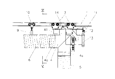
The exhaust gas extraction apparatus comprises a running rail l, which is
mounted in the upper shed region of a vehicle shed 2. A carriage 3 can move on
the
2o running rail l and carries a pipe bend 4. This pipe bend 4 has first pipe
connector 4a for
an elastically extensible extraction hose 5 and a second pipe connector 4b for
a
connecting hose 6 which can extend elastically in its longitudinal direction.
The
connecting hose 6 is connected to a collecting line 7, which is for its part
cpnnected to a
ventilating fan, not shown. An extraction socket 8 is disposed on the lower,
free end of
2s the extraction hose. This extraction socket can advantageously be an
extraction socket in
accordance with DE 4 214 908, which has a cuff of rubber which can be pushed
on to
the exhaust and inflated. By pressurising this cuff can be clamped on the
exhaust,
whereby on the one hand the exhaust socket 8 is held on the exhaust and on the
other
hand a seal is produced between the exhaust and the exhaust socket, so that no
exhaust
so gases can escape. Instead of such an extraction socket with an inflatable
cuff a purely
mechanically acting extraction socket 8' can however be used, as is shown in
Figure 8.
The connecting hose is suspended from the running rail 1 by means of a
plurality of
CA 02272818 1999-OS-26
-4-
supports 9, which each have rollers 10 which move in the running rail 1. A
movable
brake shoe 12 is further arranged on the carriage 3. This brake shoe 12 can be
pressed
against the underside of the running rail 1 in the braking position. On order
to actuate
the brake shoe 12 a pneumatic actuating device 13 is provided in the
embodiment
s shown in Figures 4 and 5 and a mechanical actuating device 13' in the
embodiment
shown in Figures 6 to 8. However an electrical or electromagnetic actuating
device
would also be possible. Furthermore there is a control device 14 according to
Figures 4
and 5, which acts on the actuating device 13. This control device 14 involves
a switch
14 and a pneumatic control device whose function will be explained in more
detail
Io below. In the embodiment shown in Figures 6 to 8 the control device 14' is
of
mechanical design.
The manner of operation of the described apparatus is a~ follows:
Vhhen a vehicle 15 is in the vehicle shed 12, the extraction socket 8 is
clamped
on to the exhaust 16 of the vehicle 1 S by means of its pressurised inflatable
cuff 8a. A
i5 tight seal between the exhaust 16 and the extraction system 5 to 8 is thus
produced.
When the vehicle 1 S starts and drives off, the extraction socket 8 stays
clamped fast on
the exhaust 16. While driving off, the vehicle 15 therefore pulls the
extraction hose S
behind it, whereby the carriage 3 is also pulled along with simultaneous
extension of the
connecting hose 6. When the exhaust 16 approaches the region of the door 17,
the
2o carriage 3 arrives at the region of the control cam 18 arranged on the
running rail 1,
whereby a switch of the control device 14 arranged on the carriage 3 is
actuated. The
control device provides for venting the cuff 8a, so that this comes free from
the exhaust
16 and the extraction socket is pushed off the exhaust by a push-off
device.integrated
therein. At the same time or with a time delay, the pneumatic c~-linder 13
provided as
25 the actuating device is pressurised with compressed air through the control
device 14.
The piston rod 13a presses the brake shoe 12 on to the running rail 1 and thus
brakes the
carnage 3. The carriage 5 thus comes to a standstill in the door region, as is
shown in
Figure 2. The pressurisation of the pneumatic cylinder 13 is furthermore
maintained, so
that the carriage 3 remains braked and the extraction hose S and the
extraction socket 8
so are located in the region of the door 17 in a stand-by position. The braked
carnage 3 can
also not be pulled back into its original rest position under the action of
the elastically
tensioned connecting hose 6. On return of the vehicle it is driven into the
vehicle shed 2
CA 02272818 1999-OS-26
until its exhaust 16 is in the vicinity of the door 17. The extraction socket
8 likewise
there in its stand-by position is ready to be grasped and can be pushed on
with its cuff 8a
on the exhaust 16 again. The cuff 8a is again pressurised with compressed air
via the
control device 14, by operation of a switch, not shown, and the pneumatic
cylinder 13 is
vented.
The brake shoe 12 is released from the running rail 1 through this and the
carriage 3 is freed. As the vehicle is put back into the vehicle shed 2, the
carriage can go
into its rest position shown in Figure 1, under the action of the reversing
vehicle and the
action of the elastically tensioned connecting hose 6. Since the extraction
socket 8 is
io standing ready directly in the door region and can be clamped on to the
exhaust, no
exhaust gases get into the vehicle shed and the driver does not first have to
fetch the
extraction socket 8 and the hose 5 out of the shed.
In the embodiment shown in Figures 6 to 8 the extraction socket 8' has a
clamping jaw 15, which can be actuated by a manual lever 20. The clamping jaw
is
clamped on to the exhaust 16 in Figure 8. A Bowden cable 21 leads to the
mechanical
control de~zce 14' provided on the carriage 3. This control deuce 14' has a
control lever
22 in the form of a crank lever, which is connected at one end to the Bowden
cable 21
and at the other end to a link 23 of the actuating device 13'. The brake
linkage 24 is also
part of this actuating device. A roller 24 is arranged on the free end of the
control lever.
2o A tension spring 26 which can be moved over a dead point also acts on the
control lever
22.
R'hen the vehicle 15 drives out of the vehicle shed 2 and its exhaust 16 has
reached the door region, the carriage 3 comes into the region of the control.
curve 27
attached to the running rail 1. This presses on the roller 25 and swings the
control lever
in the direction of the arrow C. The Bowden cable 21 is pulled by this and
releases the
clamping jaw 19 from the exhaust 16. The manual lever 20 turns into its chain-
dotted
position. Moreover the brake linkage 24 is brought into its straightened out
position by
the link 23 and the brake shoe 12 is thereby pressed on to the nulning rail 1.
The
carriage 3 is thus braked in the door region in its stand-by position and held
arrested
3o there. Vfhen the vehicle returns and its exhaust has reached the door
region, the
extraction socket 8' is clamped on to the exhaust 16 again, in that the manual
lever 20 is
brought out of its chain-dotted position into its position shown in full lines
in Figure 8.
CA 02272818 1999-OS-26
-6-
The Boa-den cable 21 is hereby pulled in the direction D and turns the control
lever 22
back again into its initial position. The brake is thus released and the
carriage 3 can be
moved freely again.
In order that the carriage 3 shall actually reach the door region when the
vehicle
s is driven out the uncoupling of the extraction socket 8, 8' and the braking
of the carriage
should not take place too early. The braking path of the carnage 3 is relative
short and if
the vehicle is driven out wildly, the extraction socket 8, 8' and the
extraction hose 5
experience a substantial acceleration, which could lead to the extraction hose
5 tearing.
In order to prevent this at least one control cable 28 is provided between the
pipe
to connector 4a and the extraction socket 8, 8'. Preferably however, two
control cables 28
are pro«ded. acting on diametrically opposite sides of the pipe connector 4a
and the
extraction socket 8, 8'. Each control cable 28 consists of a cable 28a and a
tension spring
28b. Moreover the length of the un-extended extraction hose ~ is at least 50
cm more
than the vertical distance A between the pipe connector 4a and the extraction
socket 8, 8'
15 resting on the shed floor 2a. The lengths of the control cables 28 and
their spring force
are so dimensioned that, as is shown in Figure 2, with the extraction hose 5
hanging
down approximately vertically, the extraction socket 8 touches the shed floor
2a. The
effect of the greater length of the extraction hose 5 is that, when the
extraction socket is
released from the exhaust, the extraction socket is braked by the control
cable 28, before
2o the inertial forces of the extraction socket can be transferred to the
extraction hose. Too
strong a loading of the extraction hose and thus tearing thereof are thereby
prevented.
Moreover the extraction socket 8, 8' can remain on the exhaust a relatively
long time,
until this has left the vehicle shed. Emission of exhaust gas into the vehicle
shed is thus
prevented. The control cables 28 fiurther result in the extraction socket 8,
8' being caught
25 and landing on the floor softly, where it is then pulled back over the
floor into the door
region of the shed under the action of the force of the tension springs 28b.
The
extraction socket then provides braking action, especially if it has a rubber
cuff 8a, so
that the extraction hose 5 is also braked and this and the extraction socket
are prevented
from flyng back. Injury to personnel is also avoided by this. In the stand-by
position the
so extraction hose 5 and socket 8, 8' assume the ready position shown in
Figure 2, in which
only the extraction socket 8 still contacts the shed floor 2a. The control
cables 28
prevent the extraction hose 5 lying on the shed floor 2a on account of its
excess length.
CA 02272818 1999-OS-26
In order to increase the operating reliability of the exhaust gas extraction
apparatus it is further advantageous if at least the pipe connector 4a for the
extraction
hose 5, but advantageously the whole pipe bend 4, is pivotally mounted on the
carriage
3 about an axis A1 running parallel to the running rail 1. This prevents
oblique forces,
which can act on the extraction hose S, also being transferred to the carriage
3. The
ability of the carriage 3 to move freely could be prevented by such oblique
forces or it
could even bind completely in the running rail 1.