Note: Descriptions are shown in the official language in which they were submitted.
CA 02273178 1999-03-26
WO 98/19617 PCT/US97/03836
1
ORTHOPEDIC IMPLANT
STATEMENT OF GOVERNMENTAL INTEREST
This invention was made with Government support under
Contract No. N00039-95-C-0001 awarded by the Department of the
Navy. The Government has certain rights in the invention.
BACKGROUND OF TFiE INVENTION
The invention relates to orthopedic (bone) implants which
are used to replace a missing or diseased portion of bone.
Several conditions can lead to the' loss of bone including
trauma, arthritic diseases, tumor:, musculoskeletal defects,
and the replacement of a failed implant.
An intramedullary implant is generally used in long bones
(i.e., the femur and humerus), an~i is inserted into the medul
lary canal, which runs through the diaphysis (shaft) of the
bone and is filled with bone marrow. A long bone implant is
one of two different types of intramedullary implants, the
other being categorized as joint replacements. The joint
replacement implants (i.e., a hip or knee implant) have a much
~ more complicated geometry, than the rod-like, long bone re-
placement. Both types of implant: have shown similar modes of
failure in clinical studies.
The intramedullary implants being used today are generally
fabricated from metal, using an allloy of either titanium (Ti)
or cobalt chrome (Co-Cr). The joint replacement implants are
primarily made with a Co-Cr alloy containing molybdenum (Mo),
which is added to improve the wear resistance properties of the
material, an important consideration when the implant is used
to replace articulating surfaces.
'30 Long bone replacement implant, are most commonly fabricat-
ed from Ti, either in its commercially pure state or as an
alloy with aluminum and vanadium. These materials have been
CA 02273178 1999-03-26
WO 98/19617 PCT/LTS97/03836
2
experimentally and clinically proven to be biocompatible.. It
is not completely understood biochemically, but the bone tissue
grows and attaches to the surface of Ti more readily than to
other materials. This property allows Ti to aid in the fixa-
tion of the implant in bone, an extremely important part of the
operation directly affecting the duration of success.
It is important for implant success that the implant
remain stationary so the bone tissue can begin to grow around
it. Initial stabilization is achieved through the use of bone
cement applied during surgery, which acts as a filler between
the bone and the implant. The interfacial space is filled with
cement to stabilize the implant and inhibit motion. The bone
cement material is a thermoset particulate composite polymer
called polymethylmethacrylate (PN~tA).
Long term stabilization of the implant in bone is achieved
by having a porous coating on the surface of the implant. The
porous coating is either added or molded onto the surface of
the implant. Ti or hydroxyapatite (HA) are two materials with
good biocompatibility and/or biostimulating factors commonly
used to create this porous coating. Ti is sintered onto the
metal (e.g., Ti) implant in either a mesh of crimped wire or a
random array of particulates. The HA is applied to the surface
of the implant using plasma spraying techniques.
The surface coating must have large enough pores to allow
the bone cells to travel through and create a strong interlock-
ing fixation by reconnecting with adjacent bone tissue through-
out the mesh. This method of fixation relies on the connection
of the bone tissue to hold the implant in place. If the bone
tissue does not grow fast or is not strong enough, the implant
is not completely stabilized and micromotion can occur.
Problems with current implant designs stem from the
difference in mechanical properties between the materials used
in the implant system and the bone itself. The Ti alloy has an
elastic modulus equal to 110.3 GPa (16.0 X 10⁶ psi), and the
Co-Cr alloy has an elastic modulus equal to 210.3 GPa (30.5 X
106 psi). In comparison to the modulus of cortical bone, equal
CA 02273178 1999-03-26
WO 98/19617 PCT/IJS97/03836
3
to about 13.8 GPs (2.0 X 10⁶ psi), these metallic implants. are
a minimum of eight times stiffer. This large gradient causes
stress shielding across the implant-bone interface, where the
implant supports and absorbs most of the load and leaves the
bone virtually inactive and unstressed.
As stated in Wolff's law, bone needs to be cyclically
stressed to survive and remain strong enough to support the
body. The shielded, unstressed bone around a metal implant
begins to resorb and cavities form between the implant and the
bone. The cavities weaken the fig:ation and allow micromotion
of the implant in the bone, eventually producing local wear
debris. Microscopic foreign body wear debris in the surround-
ing tissue will trigger the body'; defense mechanism and cause
infectious reactions. Loosening of the implant is irrevers-
ible without intervention and ultimately leads to a revision
operation. A patient can only undergo two or three additional
procedures before the bone becomes. too weak and osteoporotic to
support another replacement and is. considered non-functional.
SUN~lARY OF THE INVENTION
The isoelastic bone-implant system of the invention
minimizes, if not eliminates, the stress shielding effect
created by a metal implant, thus, leading to a longer implant
lifetime in the body. In one embodiment, a thermoplastic
polymer with an elastic modulus approximating the modulus of
bone is used for the implant.
Since bone is a natural composite material composed of a
matrix with organic and inorganic substances, composites are
also an excellent choice of materials to use for implants,
specifically for those situations where material properties
have a large impact on the implant.~s success, such as replace-
ment of a hip. Hence, a second embodiment comprises a composite
comprising a thermoplastic polymer and a reinforcing material,
the composite having an elastic modulus approximating the
elastic modulus of bone. The composite preferably comprises
CA 02273178 1999-03-26
WO 98/19617 PCT/US97/03836
4
polyetheretherketone (PEEK), a high temperature thermoplastic,
containing preferably 10% by volume of chopped E-glass fibers
which results in a material having approximately the same
stiffness as bone and, therefore, in a significant improvement
with respect to the stress-shielding problem.
The final step is the application or formation of a porous
coating on the surface of the implant to create the porous
environment for bone ingrowth. The coating can comprise
hydroxyapatite applied to the surface, a roughness formed on
the surface, or a biocompatible material such as titanium
embedded in the surface.
A two piece embodiment of an intramedullary implant is
joined and locked together, after the opposite ends of each
piece are inserted in the medullary canal, using an interlock-
ing mechanism comprising a fluted protrusion on one piece and a
corresponding fluted cavity in the other piece with the fluted
portions being complementarily tapered.
BRIEF DESCRIPTION OF THE DRAWINGS
Fig. 1 illustrates the orientation parameters in the SMC
Micromechanics Model for Composite Materials software program.
Fig. 2 illustrates a three-dimensional finite element
. model (FEM) of a prosthesis with bone cement, and cortical bone
with extracortical bone bridging.
Fig. 3 is a plot of the stress gradients through the
different material layers for the metallic and composite
implants produced from the FEM.
Fig. 4 is a schematic representation of the in-house
injection molding assembly.
Fig. 5 is a photograph of a randomly selected, longitudi-
nally sectioned PEEK/10% glass preform.
Fig. 6, consisting of Figs. 6a and 6b, are, respectively,
an image showing relatively aligned fibers (darkened) lying
predominantly in the 1-2 plane; and an example of fibers
pointed into the plane, and thus not chosen for measurement of
orientation.
CA 02273178 1999-03-26
WO 98/19617 PCT/US97/03836
Fig. 7 illustrates the implant of the invention with.the
mating flutes and the tip flutes.
Fig. 8, consisting of Figs. 8a and 8b, shows, respective-
ly, the winding of the Ti coil. around [a section of] the
5 implant; and a magnified picture of the embedded Ti in the
surface of the PEEK.
Fig. 9 illustrates a push-out test cross-section of epoxy
(magnified 2X), representing bone tissue, that surrounded a
PEEK implant that did not have a Ti wire coil embedded in the
implant surface.
Fig. 10 is a plot of load v. displacement for four push-
out tests for sections of epoxy, representing bone tissue,
surrounding a PEEK implant having a Ti wire coil embedded in
the implant surface.
Fig. li illustrates a push-out cross-section of the epoxy
(magnified 2X), representing bone tissue, that surrounded the
PEEK implant with Ti wire coil embedded therein.
Fig. 12 illustrates the PEEK implant with embedded Ti wire
coil (magnified 2X) after being pushed completely through the
epoxy.
DETAILED DESCRIPTION OF THE INVENTION
The first step in producing the implant of the invention
was to develop a material that has similar bulk mechanical
properties to those of bone. A number of polymers have such
properties including some polymers that may be stiff enough to
use as an implant without the need for reinforcing fibers,
e.g., Poly-X"' Self-Reinforced Polymers manufactured by Maxdem
Inc. of San Dimas, California. A key aspect of the invention
is the use of a material as an implant that has an elastic
'30 modulus approximating the elastic modulus of bone.
For a composite implant, a high temperature thermoplastic
polymer, polyetheretherketone (PEEK), was chosen as the resin,
or matrix, material for its relatively comparable strength,
high toughness and previously recorded biocompatibility with
CA 02273178 1999-03-26
WO 98/19617 PCT/US97/03836
6
human tissue cells. E-glass fibers were selected as the
reinforcing material for their strength.
Although carbon fibers can be used in PEEK, glass fibers
were chosen because the material was more cost effective, and
the injection molding of the preforms (described below) was
easier because the glass fibers are less abrasive than carbon.
Most importantly, the glass fibers are transparent to radiation
therapy and will not create shadows or interfere with post-
operative treatment. Properties of these constituent materials
are listed in Table 1.
Table 1
ELASTIC MODULI FOR THE RESIN AND FIBER MATERIALS OF THE COMPOS-
ITE
Material Elastic Modulus GPa (psi) Poisson's Ratio
PEEK resin 4.2(0.6 x 10⁶) 0.41
E-glass fibers 72.4(1.1 x 10') 0.20
To predict the properties of PEEK with glass fibers, a
software package, called SMC Micromechanics Model for Composite
Materials, developed to determine thermoelastic properties of
fiber reinforced composite materials, was used. This program
uses the constituent properties of the resin and reinforcement
phases, their composition, the fiber aspect ratio, and degree
of orientation of the reinforcement throughout the resin, to
calculate a longitudinal modulus for the composite material.
The longitudinal modulus for the implant substrate being
created was chosen to be slightly lower than that of bone in
anticipation of the additional stiffness and strengthening of
the biocompatible, metallic porous surface to be added later on
in the fabrication process.
Commercial compounding services typically provide fiber
volumes of 100, 20o and 30% for both glass and graphite fibers.
These are the compositions used in the SMC program to determine
material properties. Instead of relying solely on commercial
CA 02273178 1999-03-26
WO 98/19617 PCT/US9~/03836
7
data published for these materials, the program was used to
predict the properties of the same compositions but with
varying fiber orientations:
Two parameters are used to describe the fiber orienta-
tions. The parameter fp describes. the planar fiber orientation
in the 1-2 plane, and fa defines the axial orientation rela-
tive to the 3 axis (Fig. 1). The program was run to find the
range of moduli for each composition from a completely random
distribution of fibers to a relatively aligned distribution.
The values are listed in Table 2.
Table 2
OUTPUT FROM SMC PROGRAM FOR PEEK COMPOSITES
Longitudinal Modulus
GPa (psi)
Composition (% fiber) Completely Random Perfectly Aligned
10% E-glass 6.05 10.54
( 0 . 88 x 106) ( 1. 53 x 106)
20% E-glass '8.22 16.98
(1.19 x 10⁶) (2.46 x 10⁶)
30% E-glass 10.65 23.15
(1.55 x 10⁶) (3.36 x 10⁶)
10% graphite 6.89 16.27
(0.99 x 10⁶) (2.36 x 10⁶)
A composition of PEEK with 10% glass fibers had a predict-
ed modulus range from 6.05 GPa (0.88 X 10⁶ psi) to 10.54 GPa
(1.53 X 10⁶ psi) for completely random to completely aligned
fiber orientations respectively. Note that both values are
still less than the modulus of bone of 13.79 GPa (2 X 10⁶ psi).
The lowest volume ratio (10%) of graphite fibers available
predicted a range of moduli with an upper limit that was
already greater than the modulus of bone. Therefore, the
composition of PEEK with 10% glas:a fibers was chosen to be the
substrate material for the composite implant.
CA 02273178 1999-03-26
WO 98/19617 PCT/US97103836
8
The properties determined by SMC were then used in the
development of a finite element model (FEM), created using
COSMOS/M Finite Element Analysis Software. The model was made
to study the induced stresses surrounding a bone replacement in
vivo and compare the differences between a metallic and a
composite implant. The model contains an implant, bone cement,
cortical bone, and extracortical bone layer in a three-dimen-
sional array shown in Fig. 2. The stresses resulting from an
applied bending moment were studied, since they had more
significance than the stresses resulting from axial and tor-
sional loads. A comparison was made between the resultant
stresses of a Ti and 10~ glass-PEEK implant.
The bending moment applied to the FEM produced longitudi
nal stresses through the implant and the bone, the most criti
cal stress case in consideration of stress shielding. The
magnitudes of the stresses, in a section where the extra-
cortical bone bridging is the thickest, were plotted in Fig. 3.
The gradients of these stresses radially outward, through the
extracortical bone, cortical bone, bone cement, and implant
layers, are evident in the graph.
While the stress that the composite implant bears is much
lower than that for the metallic implant, the stress in the
cement and bone layers are higher for the composite implant
than for the Ti. This is a direct result of matching the
elastic modulus of the composite to that of bone. The compos-
ite implant is not bearing as much load as the metallic im-
plant, allowing the bone to absorb more of the applied load.
Therefore, the cortical bone layer bears more load when using
the composite implant, theoretically confirming that an implant
with properties closer to that of bone leads to the elimination
of the stress shielding effect evident with higher modulus
metallic implants.
Prototypes of the composite implant were made using a
pressure/injection molding system, shown in Fig. 4, developed
specifically for this project. The assembly consists of a
reservoir (1), where the material sits and heats up to its
molten state, with a channel (2) that is opened and closed by a
CA 02273178 1999-03-26
WO 98/19617 PCT/US97/03836
9
two-way valve connecting the reservoir to the mold (3), wh~.ch
is tightly clamped together. The injection speed was con-
trolled by pressure applied via a piston (4) to the material in
the reservoir. The material was released when the valve was
opened and pushed into the end of the mold in the direction of
the long axis of the part. Temperatures of the reservoir and
the mold were controlled individually by a set of four heaters
each.
To condition the system initially, lower temperature
thermoplastic materials were used. This allowed trial observa-
tions of the process and the discovery of any necessary modifi-
cations to be made, prior to injecting the high temperature
PEEK. Molding parts using ultra high molecular weight polyeth-
ylene, acrylic, polycarbonate, and glass fiber filled poly-
carbonate progressively seasoned the tool to the higher temper-
atures. The modifications made were done to improve the
density of the parts being produced, including the addition of
bleed holes in the mold to allow t:he escape of air pockets and
the adjustments of the injection and back pressures held on the
part. Through this trial period, it was discovered that a high
pressure at the opening of the valve followed by a lower
pressure during cooling of the part increased their density.
Small pellets of 10% glass-filled PEEK, were heated up to
. 680°F to reach its molten state. Since PEEK is such a highly
viscous material even in its molten form, the injection pres-
sure was set at 75,000 psi. A 30,000 psi back pressure was held
while the part cooled from 450°F to 275°F. The high initial
pressure created the fastest injection speed within the con-
straints of the system, and the back pressure forced residual
air pockets to escape. The production rate was fairly slow due
to the lag time in heating and cooling the system each day, the
limited amount of material used from one filling of the reser-
voir, and the manual assembling and disassembling of the mold
. to make each individual part.
The prototype molded part is .a preform of the final
implant. Several additional machining and molding processes
CA 02273178 1999-03-26
WO 98/19617 PCT/US97/03836
have to be performed to reach the final shape. Testing was
done to prove that the material properties of the molded parts
were consistent with those of commercially provided material
samples. Scanning was performed to make a visual assessment of
5 the part density. A cross-section was photographed under
magnification to measure the fiber distribution throughout the
body of the part.
Unlike a high production commercial extruder/injection
line, the material processed in the above assembly remained
10 molten for a much longer time, resulting in some oxidation.
Characterization testing was performed to confirm that the
parts being produced had retained the original material proper-
ties. Tensile tests were run on a group of six randomly
selected molded preforms machined to fit an extensometer and
have a one inch gage length.
The tensile test results were compared with those from
tensile tests done on commercially supplied tensile bars of
different compositions of glass-filled PEEK. The commercial
tensile bars were run to failure and ultimate tensile strengths
were measured. The "in-house" samples failed in the threads
used to fit the machine and the ultimate tensile strengths were
never reached. The elastic moduli, listed in Table 3, were
comparable for all tests, confirming the predictions of the SMC
program and verifying that the material integrity was conserved
through the in-house molding process.
CA 02273178 1999-03-26
WO 98/19617 PCT/US97/03836
11
Table 3
TESTING RESULTS CONFIRMING ORIGINAL MATERIAL PROPERTIES
Material Elastic :Modulus Tensile Strength
GPa (psi MPa (Psi)
bone ( f emur ) 17 . 2 121. 0
(2.49 :~c 106) (17, 500)
neat PEEK 3.66 0.13 92.7 1.05
(0% glass) (0.53 0.02 x 10⁶) (13,450 151.7)
molded 10% 7.86 2.17 81.1 13.56**
glass/PEEK* (1.14 0.32 x 10⁶
(11,765 1966.6)**
commercial 10% 6.62 1.99 110.72 8.71
glass/PEEK (0.96 0.29 x 10⁶) (16,060 1262.7)
commercial 20% 8.96 0.49 149.33 2.47
glass/PEEK*** (1.30 0.07 x 10⁶) (21,660 357.8)
commercial 30% 1.10 0.79 164.62 1.42
glass/PEEK*** (1.60 0.12 x 10⁶) (23,877.5 206.6)
* in-house molded preforms
** tensile strength measured when failed at threads
***commercially provided AST1M standard tensile test bars
The PEEK/10% glass composite preforms were also evaluated
non-destructively via C-scanning to observe if there were voids
or air pockets in the parts that might eventually interfere
with the strength of the part. The scans were calibrated to a
sectioned part to see what signals corresponded to impurities
and discontinuities in the material. The rest of the parts
were non-destructively scanned, a:nd the results showed consis-
tently solid parts with no significant defects.
A random preform part was chosen and cross-sectioned,
exposing the flow pattern of the injected composite material
(see Fig. 5). Images of the micro-polished cross section were
captured at 40X magnification using an optical microscope,
producing a clear picture of the fibers. The image was then
digitally imported into NIH Image software to measure the fiber
off-axis angles with respect to t:he horizontal (longitudinal
axis). Fiber angles were measured from images taken along the
center-line of the part in a two-dimensional plane, spaced
approximately 0.1375 inches apart. The angle measured from
CA 02273178 1999-03-26
WO 98/19617 PCT/US97/03836
12
these images represents the position of the fiber in the 1-2
plane as described with the SMC program (see Fig. 1).
Only the fibers that were predominantly laying in that
plane were selected to be measured (Fig. 6a). The average off-
axis angle was 26.13 degrees with the range spanning from 0
degrees to 93.92 degrees. Assuming that the same results would
be seen in the plane going into the screen (Fig. 6b), these
images confirm that the fiber orientation may be classified as
completely random. The values taken from the SMC data are
further verified to be accurate with the modulus predicted and
the orientation assumed with input.
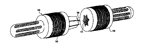
As shown in Fig. 7, an implant of the invention comprises
first and second pieces 10, 12, each with a tip or end that
fits into the intrameduliary canal and extends from a wider
body that has the porous coating to support the growth of
extracortical bone. Each tip is inserted into the medullary
cavity of either end of the fractured bone at the diseased or
damaged site deep enough to assure anchorage into healthy bone.
The second piece has a cavity 14 for receiving a protruding
member 16 on the first piece. The two pieces which are comple-
mentarily tapered for ease of alignment and assembly are joined
by being tapped together and locked by the tapered press fit.
The intramedullary implant is also designed with a means
for resisting rotation between the first and second pieces. In
one embodiment this comprises a six-fluted interlock to insure
that the implant is rotationally stable. Flutes were chosen to
minimize stress concentration while maximizing interlock or
fixation but any keyed or indexed means to prevent rotation,
such as notches and recesses, are acceptable. In addition to
using an adhesive to seal this connection, the mating flutes
apply a positive lock during torsion.
The design of a six-fluted mating interlock is alterable
in consideration of the surgical procedure for implanting these
devices. The addition of more flutes would retain the strength
and resistance to torsional forces, while decreasing the angle
between each mating flute. This decrease in angle would make
CA 02273178 1999-03-26
WO 98/19617 PCT/US97/03836
13
it much easier to match the two halves when securing them
together during surgery, where time may be a major concern.
The interlocking flutes are molded onto/into the ends of
the preforms, and are designed to have a friction lock when
tapped together, making the sizing and accuracy of the molding
very critical. The flutes on the tips (the ends that are
inserted into the medullary cavity of bone) provide more
- surface area for the bone cement t:o fill and hold the implant
in place.
The final step in making the implant is to embed a tight
Ti coil 18 (Fig. 7) into the surface of the body of the implant
by, for example, wrapping the coil_ around the implant and
pressing the coil into the polymer after or during an applica-
tion of heat. Titanium is used for its biocompatibility. The
critical design aspect of this surface, aside from achieving a
strong attachment of the Ti to the: composite, is its porosity.
In order to allow the necessary bone cells to fit through the
pores and create the desired mechanical interlock, the pores,
i.e., the interstices between the exposed (nonembedded) por-
tions of the Ti wire coil, should be in the range of 150-200 ~m
which may require that the wire coil be inter-meshed, i.e.,
overlapped, to achieve.
The desired porosity may also be achieved by using IAA on
the implant surface instead of Ti or, without Ti or HA, by
forming different surface roughne:uses on the material forming
the implant. Surface roughness on any material increases bone
cell attachment and can be created by using a mold with a
roughen surface or by some treatme:nt, e.g., etching, sanding or
sandblasting, of the implant after the molding process.
The titanium coil can be embe=dded into the polymer via one
of several methods, all of which :should be done in a vacuum or
inert gas atmosphere: 1) the coi7l is heated via electrical
resistance while being pressed int=o the polymer; 2) the coil is
preheated in an oven and then plac=ed around the polymer while
being pressed into place; 3) the c=oil is heated by induction in
a high frequency RF field while be=ing pressed into the polymer-
ic surface; 4) the coil and polymesr surface are both heated by
CA 02273178 1999-03-26
WO 98/19617 PCT/US97103836
14
a focused hot gas stream while the coil is pressed into the
polymer; and 5) the coil and the polymer are both heated at the
intersection point by a focused infrared beam while the coil is
wrapped around the polymeric implant and imbedded. In each
case the coil should only be embedded in polymer 1/3 to 1/2 of
its diameter when the process is completed. Also, the mecha-
nism for imbedding the coil should not interfere with the
heating method.
The result is a process that leaves the Ti coil embedded
into the surface of the PEEK approximately halfway, as shown in
the photographs in Fig. 8. Push out tests were performed to
prove the Ti coil was securely embedded and mechanically locked
into the surface of the PEEK implant. For each test, a section
of the implant was set in an epoxy, using a 33:100 ratio of
EPON Curing Agent V-40 to EPON Resin 826. The epoxy repre-
sented bone tissue surrounding the implant, creating a mechani-
cal interlock through and around the Ti coil. The tests were
done on an Instron Machine performing general compression of a
cylinder.
In order to prove that the results of the push-out tests
represent the forces at the interface of the coil and the
epoxy, instead of the PEEK and the epoxy, an initial test was
done using a section of the implant without any coil embedded
in the surface. The results showed that there was no bonding
of the epoxy to the PEEK. The implant was smoothly pushed out
with a maximum load of 540 lb, creating a shear stress of 419
psi. Fig. 9 is a cross-sectional picture of the epoxy that
surrounded the part. It is obvious that there was no shearing
or failure of the epoxy, which would have resulted if it bonded
with the PEEK.
Tests were then done using sections of the implant with
the coil embedded in the surface. Three tests were done with a
low rate of displacement, applied at a constant 0.05 in/min.
The maximum recorded push out load was an average of 3386 lbs,
with an average maximum shear stress of 2269 psi. Test 4 was
done with a higher rate of displacement, applied at a constant
CA 02273178 1999-03-26
WO 98/19617 PCT/US97/03836
10 in/min. The maximum force approximately doubled compared to
the slower tests.
The load vs. displacement curves for all tests are shown
in Fig. 10. The consistency is obvious with tests 1-3 and a
5 steeper slope is shown for test 4 (this maximum force was not
recorded quickly enough and was therefore estimated from the
ultimate shear stress of the epoxy, since the epoxy completely
failed). Fig. il is a cross-sectional picture of the epoxy
that surrounded the part. The Ti sheared out of the epoxy and
10 remained completely anchored in the PEEK, eventually fracturing
the epoxy. The mechanical interlock of the epoxy in the coil
pulled the epoxy with it as it was pushed through. Fig. 12
shows the part after being pushed completely through the epoxy.
The amount of epoxy that remained attached to the coil proves
15 that the mechanical interlock of the material through the
porous surface is extremely strong'.
The push out tests confirm that the Ti coil is mechanical-
ly locked in the surface of the implant. Considering that the
most damaging strain the implant/c:oil interface would experi-
ence when implanted in vivo is in shear, these tests have
proven that the Ti coil is essentially permanent in the sur-
face. The amount of epoxy remaining in the coil as it was
pushed through shows that this type of porous surface is more
than adequate at providing enough space for a material (i.e.,
the epoxy in the test and bone tissue in vivo) to grow through-
out it and create a mechanical interlock. Test 4 (performed
with a higher rate of displacement:) simulates a worst case
scenario of the force the implant might see if the repaired
bone experiences a major impact.
Clinically, the use of an implant that has an elastic
modulus approximating the elastic modulus of bone will have a
great impact on the orthopedic industry. Long term advantages
of this new technology include a decline in the amount of
revision surgeries necessary, reducing the rise of health care
costs. The new implant will have a longer fatigue life, which
will better serve the younger patient population, with a lower
probability of recurring pain and surgery for the patient.