Note: Descriptions are shown in the official language in which they were submitted.
CA 02273346 1999-08-18
DITTO-22
FOLDING TABLE RELEASE LATCH APPARATUS
BACKGROUND OF THE INVENTION
The present invention pertains generally to folding
furniture and, more specifically to tables having legs that fold
compactly underneath the tabletop. In particular, the invention
concerns an folding apparatus for extending and retracting the
legs and a latch mechanism for locking the legs in position.
Folding tables are widely used and derive their primary
benefit from the relative ease with which they can be handled and
stored when in the folded condition. One typical folding table
leg is described in the patent to Weagle, U.S. Patent
No.3,695,567. Folding tables of this type do not include a cross
brace that provides fore and aft support for the table leg.
Another difficulty with folding table designs such as the
configuration shown in the Weagle patent is that the folded legs
do not provide a uniform surface on which other folded tables may
be stacked because the legs overlap each other.
An alternative design is a trestle-type table, such as the
folding table shown in the patents to Burr, Nos. 3,818,844 and
4,444,124. In these tables, the vertical legs do not overlap
each other; however, like the Weagle device, the folded legs
themselves provide the stacking surface for other folded tables.
An additional difficulty associated with trestle-type tables is
that they are often difficult to fold and handle once folded.
In U.S. Patent No. 4,838,180, owned by the assignee of this
invention, the present inventor sought to overcome many of the
CA 02273346 1999-08-18
DITTO-22 2
disadvantages of prior folding tables. This '180 patent
describes a folding table that allows the table legs to be
compactly folded underneath the tabletop, while still providing a
uniform surface on which other tables may be stacked. One
benefit of the folding table leg apparatus shown in the '180
patent is that the stacked tables are not supported on the folded
legs, but rather on upright flanges forming part of the folding
leg apparatus.
Certain details of the folding table leg apparatus of the
1180 patent is depicted in FIG. 1. As shown in this figure, the
folding leg apparatus 10 includes a top plate 11 that is mounted
to the underside of a tabletop. The top plate 11 includes
opposite side flanges 12 that project perpendicularly outward
from the top plate 11. Rubber pads 14 are mounted at the edges
of the side flanges 12 to provide a scratch resistant surface
upon which a tabletop may be supported.
The folding leg apparatus 10 of this prior device includes a
single tubular vertical leg 15. As shown in more detail in the
1180 patent, the vertical leg 15 terminates in a base or foot
that is configured to support the table on the floor. A pair of
support brackets 20 are each mounted to the top plate 11 at
opposite sides of the vertical leg 15. The support brackets
provide an attachment or pivot point for a pair of brace links
25. The brace links 25 are pivotally connected at one end to the
support bracket 20 and at the other end to the vertical leg 15 by
way of a lower pivot rod 28 that passes through the tubular leg.
The vertical leg 15 is also supported by an upper pivot rod 35
that spans substantially across the width of the top plate 11.
The upper pivot rod 28 is pivotally connected to the side flanges
12 by way of opposite swivel brackets 47. Thus, the brace links
25 and swivel brackets 47 provide a mechanical linkage for
CA 02273346 2006-06-14
29512-25
3
controlled movement of the vertical leg 15 between its folded and
its extended positions.
In a further aspect of this prior apparatus, a pair of
release brackets 40 is provided for positively locking the upper
p;-vot rod 35 in place when the vertical leg 15 is in its extended
position. Each of the release brackets includes a lever arm 41
and an actuator plate that is manually depressed to release the
upper pivot rod. A torsion spring 44 provides a positive torque
to each lever arm 41 to keep it in its locked position when the
release brackets 40 are engaged to the upper pivot rod. In this
manner, the folding leg apparatus 10 of the '180 patent provides
a positive locking mechanism to hold the vertical leg in its
extended position. Likewise, the release brackets 40 provide an
easy way to release the upper pivot rod so that the vertical leg
can be rotated and pivoted to its stowed position. Greater detail
concerning the folding leg apparatus 10 of this prior device can
be found in the specification of the '180 patent.
While the folding leg apparatus 10 of the '180 patent
represents a significant improvement over prior folding leg
apparatus, certain difficulties still remain. One particular
problem is that the release brackets 40 are oriented so that they
can be accidentally actuated under the table. For example, a
person sitting at a conference table could accidentally contact
one or both of the release brackets with their leg.
Another difficulty is that the direction of movement of the
table leg when the release brackets are actuated can create the
risk that the operator's fingers will get pinched in the folding
mechanism. There is therefore a need for improvements to these
various folding table leg apparatus that retains beneficial
features that allow the apparatus to be easily folded and readily
stowed. The need encompasses providing a folding table leg
CA 02273346 1999-08-18
DITTO-22 4
apparatus that sows the leg in such a manner as to permit
stacking of folded tables.
Moreover, none of the prior folding leg apparatus is readily
adapted to dual upright legs. The device in the '180 patent
accommodates a single post leg. An additional detriment of some
prior devices is that they require manipulation of two release
levers to actuate the folding mechanism. While this detriment is
of little concern for a single post leg, it is compounded with a
dual upright leg that spans a width that is too difficult for the
operator to manipulate.
CA 02273346 1999-08-18
DITTO-22 5
SUbIlKARY OF THE INVENTION
These difficulties with prior folding leg apparatus is
addressed by the apparatus and latch apparatus of the present
invention. The invention has particular applicability to folding
tables in which the table legs include at least two upright bars
disposed apart from each other. In the preferred embodiment, the
apparatus includes a pair of support brackets having means for
mounting the brackets to the top of the article of furniture, or
tabletop, such that said support brackets straddle the upright
bars of the leg. Each of the brackets defines an elongated
upstanding flange having a first end and an opposite second end.
An upper pivot rod and a lower pivot rod are affixed to the
upright bars adjacent the top end of the bars, with the upper
pivot rod located closest to the top end.
In a further aspect of the invention, a pair of swivel
brackets are each pivotably connected at one end thereof to a
corresponding end of the upper pivot rod. The swivel brackets
are further pivotably connected at an opposite end thereof to the
first end of the flange of a corresponding one of the support
brackets. The apparatus further includes a pair of brace links,
each pivotably connected at one end thereof to a corresponding
end of the lower pivot rod and at an opposite end thereof to the
second end of the flange of a corresponding one of the support
brackets.
A latch release mechanism includes a release lever defined
by an elongated actuator plate substantially spanning between the
flanges of each of the support brackets. The release lever also
includes a pair of lever arms integral with the opposite ends of
the actuator plate. Each of the lever arms defines a locking
notch configured to capture the upper pivot rod therein. In one
important feature of the invention, the mechanism includes means
for pivotably mounting the release lever to the flange of each of
said support brackets with the actuator plate disposed between
CA 02273346 1999-08-18
DITTO-22 6
said second end of the flange and the means for pivotably
mounting. The means for pivotably mounting is configured so that
the release lever is pivotable between a first position in which
the locking notch captures the upper pivot rod and a second
position in which the locking notch is separated from the upper
pivot rod. In the most preferred embodiment, the means includes
a torsion spring operatively anchored to the flange to bias said
release lever to the first position. Torque from the spring is
conveyed to the release lever through a bolt that is rotatably
mounted through the flange and non-rotatably connected to the
lever arms of the release lever. In a preferred embodiment, the
bolt includes a keyed stem that fits within a keyed bore defined
in the lever arms. The release lever is movable to the second
position by depressing the actuator plate toward the support
bracket or tabletop.
In further aspects of the invention, the lever arms of the
release lever each define a guide channel opening to the locking
notch that is positioned to guide the upper pivot rod out of the
locking notch when the release lever is pivoted to the second
position. The lever arms also define a foot portion opposite the
locking notch that has a foot edge for contacting the support
brackets when the release lever pivots in the direction from the
first position to the second position. With this feature, the
release lever is maintained in a readily accessible position when
the table leg is in its folded position.
In certain embodiments, the table leg is maintained in its
upright position simply by the linkage formed by the swivel
brackets and the brace links, as maintained by the lever arms of
the latch release mechanism. In other embodiments, the upper
pivot rod is held against an edge of the flanges, and more
particularly in recesses defined in the edges of the flanges.
It is one object to provide a folding mechanism for a
folding table leg that is easy to manipulate without risk of
CA 02273346 2006-06-14
29512-25
7
injury to the operator. Another object is to provide a
readily releasable latch that positively holds the table leg
in its upright or extended position.
A further object of the invention is realized by
features that allow the folding leg apparatus to maintain a
low profile next to the underside of the tabletop. These
features then allow the folding tables to be stacked on top
of each other without risk of damage to the folding
apparatus or latch mechanism.
According to one aspect of the present invention,
there is provided a folding leg apparatus for an article of
furniture having a top and at least one leg movable between
an extended and a folded position, the leg formed by at
least two upright bars disposed apart from each other and
having a foot portion attached at the bottom end of the
upright bars, with the top end of the upright bars disposed
adjacent the top of the article of furniture, the apparatus
comprising: a pair of support brackets having means for
mounting said brackets to the top of the article of
furniture such that said support brackets straddle the
upright bars of the leg, each of said brackets defining an
elongated upstanding flange having a first end and an
opposite second end; an upper pivot rod attached to the
upright bars adjacent the top end; a pair of swivel
brackets, each pivotably connected at one end thereof to a
corresponding end of said upper pivot rod, and pivotably
connected at an opposite end thereof to said first end of
said flange of a corresponding one of said support brackets;
a lower pivot rod attached to the upright bars distal the
top end; a pair of brace links, each pivotably connected at
CA 02273346 2006-06-14
29512-25
7a
one end thereof to a corresponding end of said lower pivot
rod and pivotably connected at an opposite end thereof to
said second end of said flange of a corresponding one of
said support brackets; and a latch release mechanism
including; a release lever defined by an elongated actuator
plate substantially spanning between said flanges of each of
said support brackets and a pair of lever arms disposed at
opposite ends of said actuator plate, each of said lever
arms defining a locking notch configured to capture said
upper pivot rod therein; and means for pivotably mounting
said release lever to said flange of each of said support
brackets with said actuator plate disposed between said
second end of said flange and said means for pivotably
mounting, so that said release lever is pivotable between a
first position in which said locking notch captures said
upper pivot rod and a second position in which said locking
notch is separated from said upper pivot rod, said means
including a torsion spring operatively anchored to said
flange to bias said release lever to said first position,
said release lever movable to said second position by
depressing said actuator plate, whereby each of said swivel
brackets is prevented from rotating about said opposite end
thereof when said upper pivot rod is captured within said
locking notches of said release lever, to thereby prevent
movement of the upright bars of the leg from the extended
position, and whereby each of said swivel brackets is
permitted to rotate about said opposite end when said upper
pivot rod is released from said locking notches to thereby
permit movement of the upright bars of the leg to the folded
position.
According to another aspect of the present
invention, there is provided a folding leg apparatus for an
article of furniture having a top and at least one leg
CA 02273346 2006-06-14
29512-25
7b
movable between an extended and a folded position, the leg
having a foot portion attached at the bottom end and the top
end disposed adjacent the top of the article of furniture,
the apparatus comprising: a pair of support brackets having
means for mounting said brackets to the top of the article
of furniture such that said support brackets straddle the
leg, each of said brackets defining an elongated upstanding
flange having a first end and an opposite second end; an
upper pivot rod attached to the leg adjacent the top end; a
pair of swivel brackets, each pivotably connected at one end
thereof to a corresponding end of said upper pivot rod, and
pivotably connected at an opposite end thereof to said first
end of said flange of a corresponding one of said support
brackets; a lower pivot rod attached to the leg distal the
top end; a pair of brace links, each pivotably connected at
one end thereof to a corresponding end of said lower pivot
rod and pivotably connected at an opposite end thereof to
said second end of said flange of a corresponding one of
said support brackets; and a latch release mechanism
including; a release lever defined by an elongated actuator
plate substantially spanning between said flanges of each of
said support brackets and a pair of lever arms disposed at
opposite ends of said actuator plate, each of said lever
arms defining a locking notch configured to capture said
upper pivot rod therein; and means for pivotably mounting
said release lever to said flange of each of said support
brackets with said actuator plate disposed between said
second end of said flange and said means for pivotably
mounting, said means including a torsion spring operatively
anchored to said flange to bias said release lever to said
first position in which said locking notch captures said
upper pivot rod, said release lever movable to a second
position to release said upper pivot rod from said locking
notch by depressing said actuator plate.
CA 02273346 2006-06-14
29512-25
7c
According to still another aspect of the present
invention, there is provided a folding leg apparatus for a
table having a tabletop comprising: a leg having a foot at
one end for contacting the floor for supporting the table
and an opposite free end; a pair of support brackets
mountable to the underside of the tabletop and straddling
said leg; linkage means connected between the leg and each
of said pair of support brackets for permitting movement of
the table leg from an upright position in which the leg
extends from the tabletop and a stowed position in which the
leg is adjacent the underside of the tabletop, said linkage
means including a pivot bar attached to said leg adjacent
said opposite free end; and a latch mechanism including; a
release lever having an elongated actuator plate spanning
substantially between said support brackets and including a
pair of lever arms integral with said actuator plate, said
lever arms defining a locking notch configured to capture
said pivot rod therein; means for pivotably mounting said
release lever to said support brackets including a torsion
spring operatively anchored to said at least one support
bracket to bias said release lever to a first position in
which said locking notch captures said pivot rod, and
rotatable by depressing said actuator plate to a second
position in which said pivot rod is releasable from said
locking notch.
Other object and particular benefits of the
invention can be ascertained from the following written
description of the invention together with the referenced
figures.
CA 02273346 1999-08-18
DITTO-22 8
BRIEF DESCRIPTION OF THE DRAWINGS
FIG. 1 is a top elevational view of a folding table leg
apparatus as described U.S. Patent No. 4,838,180.
FIG. 2 is a perspective view of a folding table that
utilizes a double upright bar vertical leg.
FIG. 3 is a side elevational view of a table leg of the
table shown in FIG. 2.
FIG. 4 is an end elevational view of the table leg shown in
FIG. 3.
FIG. 5 is a top elevational view of a folding leg apparatus
according to the present invention.
FIG. 6 is a side elevational partial cutaway view of the
folding leg apparatus shown in FIG. 5.
FIG. 7 is a side elevational view of the folding leg
apparatus shown in FIG. 5.
FIG. 8 is a top elevational view of the release lever shown
in FIGS. 5-7, with the lever depicted as a stamped blank.
FIG. 9 is a side elevational view of the release lever of
FIG. 8 with the stamped blank depth to its operating
configuration.
FIG. 10 is an end elevational view of a bolt for the release
mechanism depicted in FIGS. 5-7.
FIG. 11 is a side elevational view of a bolt shown in FIG.
10.
FIG. 12 is an opposite end elevational view of the bolt
shown in FIGS. 10 and 11.
FIG. 13 is an end elevational view of a left-hand torsion
spring used in the folding leg apparatus shown in FIGS. 5-7.
CA 02273346 1999-08-18
DITTO-22 9
FIG. 14 is a side elevational view of the torsion spring
shown in FIG. 13.
FIG. 15 is an end elevational view of a right hand torsion
spring used with the folding leg apparatus shown in FIGS. 5-7.
FIG. 16 is a top elevational view of the lower pivot rod
used in the folding leg apparatus shown in FIGS. 5-7.
FIG. 17 is a top elevational view of the upper pivot rod
used in the folding leg apparatus shown in FIGS. 5-7.
FIG. 18 is side partial cutaway view of certain components
of the folding leg apparatus shown in FIGS. 5-7, with the leg in
its folded position.
FIG. 19 is a side elevational view of a support bracket
usable in the folding leg apparatus and depicting a modification
thereof.
CA 02273346 1999-08-18
DITTO-22 10
DESCRIPTION OF THE PREFERRED EMBODIMENT
For the purposes of promoting an understanding of the
principles of the invention, reference will now be made to one
preferred embodiment illustrated in the drawings and specific
language will be used to describe the same. It will nevertheless
be understood that no limitation of the scope of the invention is
thereby intended, such alterations and further modifications in
the illustrated embodiment, and such further applications of the
principles of the invention as illustrated therein being
contemplated as would normally occur to one skilled in the art to
which the invention relates.
A folding table is depicted in FIG. 2 that is useable with
the folding leg apparatus of the present invention. In
particular, the tabletop T is supported by a pair of legs 50.
Each of the legs 50 includes double-upright bars 52 connected to
a foot 51 that is supported on the floor. In accordance with the
present invention, each of the legs 50 can be folded underneath
the tabletop T using the folding leg apparatus of the preferred
embodiment.
In this preferred embodiment, each of the table legs has a
configuration shown in FIGS. 3 and 4. In particular, the legs 50
include two upright bars 52 that are connected at a bend 53 at
the foot end 59 of the leg. The opposite free end 58 is disposed
adjacent to the tabletop T when the leg 50 is supported by the
folding leg apparatus of the present invention. Each of the
upright bars 52 includes an upper notch 54 and a lower notch 56
adjacent the free end 58. As can be seen from FIG. 3, the
notches 54, 56 in the opposite upright bars 52 are aligned or
collinear. The upper and lower notches 54 and 56 are used to
engage the table leg 50 to the folding leg apparatus of the
present invention.
CA 02273346 2006-06-14
29512-25
I1
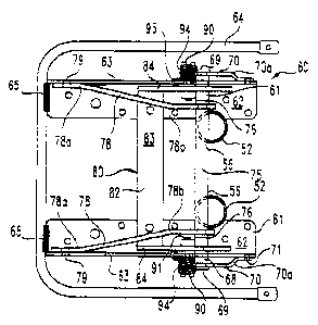
Details of the folding leg apparatus 60 of the invention are
shown in FIGS. 5-7. Particularly, the apparatus 60 includes a
pair of opposite support brackets 61. Each of the support.
brackets is defined by a mounting plate 62 and an integral
mounting flange 63. Preferably, the mounting flange 63 and
mounting plate 62 are perpendicular to each other. Each of the
mounting plates 62 includes a number of openings to receive a
fastener for engaging the folding leg apparatus 60 to the
underside of the tabletop T.
In one aspect of the preferred embodiment, the folding leg
apparatus 60 includes a lifting handle 64 that is welded at
locations 65 to each of the support brackets 61. In the
preferred embodiment, the lifting handle 64 is provided for two
purposes: first, to provide a hand hold to lift the table with
the legs in their folded position; and second, to provide a
surface for supporting the weight of another folded table stacked
on top of the particular table to which the folding leg apparatus
60 is attached. The lifting handle 64 can be configured
according to the carrying handle disclosed in U.S. Patent No.
5,390,610 by the present inventor and owned by the assignee of
this invention. Details of that carrying handle can be found in
the '610 patent.
The folding leg apparatus 60 includes an upper pivot rod 68
that is secured to the table leg 50 within the upper rod notches
54. Preferably, the upper pivot rod 68 is welded to the table
leg, although other forms of fixation are contemplated. Also
preferably, the rod 68 is cylindrical to fit within
correspondingly configured notches in the leg. The upper pivot
rod 68 is connected at its ends to opposite swivel brackets 70 by
way of pivot screws 69. The connection between the upper pivot
rod 68 and swivel bracket 70 is such that the rod can rotate
CA 02273346 1999-08-18
DITTO-22 12
relative to the bracket as the bracket itself is pivoted to
extend or retract the table leg 50. In accordance with the
invention, the swivel bracket 70 is engaged to the upper pivot
rod 68 at one end and is connected by way of a pivoting rivet 71
at its opposite end to the mounting flanges 63 of the opposite
support brackets 61.
Thus, the swivel bracket 70 is permitted to pivot relative
to the support bracket to manipulate the table leg. The swivel
bracket 70 preferably includes a bend 70a adjacent the pivoting
rivet 71 so that the bracket is connected to the upper pivot rod
68 outside the envelope of the support brackets 61.
The folding leg apparatus 60 also includes a lower pivot
rod 75 that is engaged to the table leg 50 at the lower rod
notches 56. Like the upper pivot rod, the lower pivot rod 75 is
preferably cylindrical and welded to the table leg 50. The lower
pivot rod 75 is pivotally connected to the support bracket 61 by
way of a brace link 78. Specifically, the lower pivot rod 75 is
attached to one end of each brace link 78 by way of a pivot screw
76 so that the rod can rotate relative to the brace link. The
brace link 78 itself is pivotally fixed to the mounting flanges
63 by way of a pivoting rivet 79, in a manner similar to the
swivel bracket 70.
In the specific embodiment, the brace link 78 includes a
pair of bends 78a and 78b, one bend being adjacent the rivet and
the other being adjacent the pivot screw. These bends are
arranged to orient the connection to the lower pivot rod as close
to the upright bars 52 of the table leg 50 as possible. The
narrow track of the brace links 78 and the wide track of the
swivel brackets 70 help stabilize the table leg 50 when it is in
its extended position.
CA 02273346 1999-08-18
DITTO-22 13
As thus far described, the folding leg apparatus 60 is
similar to the folding leg apparatus 10 shown in FIG. 1, which is
representative of the device described in U.S. Patent No.
4838180. In particular, the folding leg apparatus 60 retains the
upper and lower pivot rods as the means for supporting, folding
and unfolding the table leg. In accordance with the present
embodiment of the invention, the pivot rods 68 and 75, as well as
the swivel brackets 70 and brace links 78, are configured for a
table leg, such as leg 50 having dual upright bars. Again, the
use of the two pivot rods helps stabilize the upright bars 52 of
the table leg 50.
In accordance with the present invention, the folding leg
apparatus 60 includes a release lever 82 that is configured
differently from the release brackets 40 of the device in the
'180 patent. Referring first to FIG. 8, the release lever 82 can
be formed from a metal blank 82'. In the preferred embodiment,
the overall shape of the release lever is stamped out of a flat
sheet of metal to form the release lever blank 82'.
The blank defines an elongated actuator plate 83 that merges
at its ends into lever arms 84. Each of the lever arms 84
defines a locking notch 85 that is preferably semicircular in
configuration. Specifically, the locking notch 85 is formed to
receive the upper pivot rod 68 therein. The lever arms 84
further define a guide foot 87 that forms a guide channel 88
through one edge of the lever arms and opening into the locking
notch 85. The guide channel 88 is wide enough to permit free
passage of the upper pivot rod 68 into the locking notch 85.
Moreover, the guide foot 87 and the lower edge of the guide
channel 88 are oriented at an obtuse angle relative to the center
of the locking notch 85. This angular orientation of the lower
edge of the guide channel 88 provides adequate space for easy
CA 02273346 1999-08-18
DITTO-22 14
removal of the upper pivot rod 68 from within the locking notch
85. The release lever blank 82' is also stamped to form a keyed
opening 92 in each of the lever arms 84.
Looking now at FIG. 9, the final form of the release lever
82 is depicted. In particular, the release lever 82 is formed by
bending the pre-stamped blank 82' approximately at the bend lines
B shown in FIG. 8. The release lever blank 82' is bent so that
the lever arms 84 projects substantially perpendicular relative
to the actuator plate 83 so that the final form of the release
lever 82 is in the form of a "C".
Referring now back to FIG. 5, the operational orientation of
the release lever 82 can be seen. In particular, the release
lever 82 is arranged so that the actuator plate 83 is disposed
between the pivot point for the brace links 78 and the table leg
50. The release lever 82 is pivotally supported on the mounting
flanges 63 of each of the support brackets 61 by way of a bolt
90. The bolt 90 is fastened to the release lever 82 by passage
of the bolt 90 through the keyed openings 92 in each of the lever
arms 84, and is held in place by a nut 91.
Details of the bolt 90 are shown in FIGS. 10-12. The bolt
90 includes a bolt head 96 and a keyed threaded stem 97
projecting therefrom. The stem 97 is keyed to match the keyed
opening 92 in each of the lever arms 84. When the bolt 90 is
passed through the keyed openings 92, both the release lever 82
and the bolts 90 will rotate as a unit.
The head 96 of the bolt 90 also defines an enlarged spring
slot 98. In the preferred embodiment, the enlarged slot is
arranged to be parallel with the long axis of the keyed stem 97.
The slot 98 is configured to engage a portion of a torsion spring
94. In accordance with the invention, the bolt 90 extends
CA 02273346 1999-08-18
DITTO-22 15
through an opening in the mounting flanges 63 of each of the
support brackets 61. A torsion spring 94 then passes over the
head 96 of the bolt so that the anchor arm 99 of the torsion
spring 94 resides within the spring slot 98. The torsion spring
94 also includes a spring anchor 95 that is in the shape of a U
so that it can engage the upper edge of each of the mounting
flanges 63. Thus, the spring 94 operates to provide torsional
resistance against rotation of the bolt 90 relative to the
mounting flange 63, which translates ultimately into torsional
resistance against rotation of the release lever 92. As depicted
in FIGS. 13 and 14, a right handed torsion spring 94R and a left
handed torsion spring 94L are provided for engagement to the
right and left mounting flanges 63, respectively.
Looking now at FIG. 6, the orientation of the release lever
82 is shown with the table leg 50 in its extended or upright
position. In this orientation, it can be seen that the release
lever 82 is pivoted so that the upper pivot rod 68 is contained
within the locking notch 85 of the lever arm 84. In this
position, the guide foot 87 of the release lever 82 is adjacent
and generally parallel to the mounting plate 62 of each of the
support brackets 61. In this orientation it can be seen that the
brace link 78 and swivel bracket 70 are at a predetermined angle
so that the table leg 50 projects perpendicularly outward from
the tabletop T. In this position, the free end 58 of the each
upright bar 52 of the table leg is disposed adjacent to and
pointing downward toward the mounting plate 62. The release
lever 82 positively locks the upper pivot rod 68 in position so
that neither the upper pivot rod 68 nor the swivel bracket 70 can
be pivoted out of the position shown in FIG. 6. It is of course
understood that in order to fold the leg 50 underneath the
tabletop T, it is necessary for both linkages 70 and 78 to be
CA 02273346 1999-08-18
DITTO-22 16
able to pivot about their respective pivoting rivets 71 and 79.
The release lever 82 prevents this movement and positively holds
the entire release mechanism 80 against disengagement.
In accordance with the preferred embodiment, the free state
of the torsion spring 94 is such that the guide foot 87 would
rotate to the position 87' shown in phantom in FIG. 6, except
that this degree of movement is prevented by the mounting plate
62. Thus, when the release lever 82 is advanced to the locking
position shown in FIG. 6, the torsion spring 94 applies a
constant torsional pressure to keep the release lever in that
position. As a safeguard, the lower edge 89 of the guide foot 87
is arranged so that it is close to the mounting plate 62. In the
event that the release lever 82 rotates too far, the foot edge 89
will contact the mounting plate 62 to prevent over rotation of
the lever.
It can also be noted that in the locked position of the
release lever 82, the actuator plate 83 is readily accessible
within the folding leg apparatus 60. Unlike prior designs, the
actuator plate 83 is retained in a position of safety, as well as
of easy access. Thus, when it is desired to fold the table leg
50 to its stored position, the actuator plate 83 can be easily
reached and depressed, as shown in FIG. 7, without risk of
pinching the operator's fingers or hand in the release mechanism.
As the actuator plate 83 is pushed downward, the release lever 82
operates against the action of the torsion spring 94. As the
release lever 82 continues to pivot about the axis of the pivot
bolt 90 the locking notch 85 disengages from the upper pivot rod
68. With continued rotation of the release lever 82 the upper
pivot rod 68 becomes aligned with the guide channel 88 so that
the upper pivot rod 68 can be moved away from the release lever.
CA 02273346 1999-08-18
DITTO-22 17
At the position shown in FIG. 7, the table leg 50 can be
moved to its stowed position by pushing the foot of the table leg
toward the interior of the table. This action causes the free
end 58 of the upright bars 52 of the table leg to swing toward
the right as viewed in FIG. 7, thereby pivoting the swivel
brackets 70 in a clockwise direction. Continued movement of the
foot of the table leg 50 toward the interior of the table will
cause the swivel brackets 70 to continue to pivot in a clockwise
fashion, and to cause the brace link 70 to pivot in a clockwise
direction until the link members reach the position shown in FIG.
18. At this orientation, the upright bars 52 of the table leg
are generally parallel to the mounting plate 62 of the folding
leg apparatus 60. In this position, it can be seen that the
table leg 50 is within the envelope defined by the lifting
handles 64. Thus, additional tables can be stacked on the
folding leg apparatus 60 without contacting the table legs
themselves.
Details of the pivot rods are shown in FIGS. 16 and 17.
Looking first at FIG. 16, the lower pivot rod 75 includes a pivot
boss 103 and a threaded bore 104 at its opposite ends. The pivot
boss 103 is rotatably disposed within openings at the end of the
brace links 78 so that the brace links can rotate relative to the
lower pivot rod 75. Likewise, looking at FIG. 17, the upper
pivot rod 68 includes a pivot boss 100 and a threaded bore 101 at
its opposite ends. Again, the pivot boss 100 of the upper pivot
rod 68 rotatably fits within an opening at the free end of the
swivel brackets 70 so that the brackets can rotate relative to
the upper pivot rod 68. The respective pivot screws 76 and 69
engage the corresponding threaded bores 104 and 101 to hold the
pivots rods in their position relative to their corresponding
linkages, without clamping the rods in that position.
CA 02273346 1999-08-18
DITTO-22 18
The support brackets 61 can also participate in supporting
the table leg 50 in its upright position. As shown in FIG. 19,
each support bracket 61, and particularly each flange 63, defines
a support edge 107. The upper pivot rod 68 can be pressed against
this edge 107 by the torsional force applied by the spring 94 to
the release lever 82. Alternatively, the support edge 107 can
define a recess 108 that receives the upper pivot rod 68. Thus,
in some embodiments, the support brackets help restrain the upper
pivot rod, which helps prevent accidental dislodgment of the
table leg from its upright position.
The folding leg apparatus 60 of the present invention is
best suited for dual upright table legs, such as table leg 50.
In the specific embodiment, the upright bars 52 forming the table
leg 50 are separated by a distance of about 2 inches. However,
since the actuator plate 83 of the release lever 82 is a
continuous elongated plate, greater distances between the upright
bars can be readily accommodated. The release mechanism of the
present invention relies upon depressing only one plate, namely
actuator plate 83, which provides a decided advantage over the
two release brackets of the prior device shown in FIG. 1. Even
with greater distances between the dual uprights of the table
leg, the plate of the release mechanism need not span the same
distance.
In a specific embodiment, the upper and lower rod notches 54
and 56 are separated by a distance of about 2.75 inches. Each of
the notches has a diameter that is slightly greater than the
outer diameter of the upper and lower pivot rods 68, 75. The
outer diameter of the pivot rods is preferably 0.5 inches. The
swivel bracket 70 can have a length from the upper pivot rod
connection point to the pivoting rivet 71 of about 4.4 inches.
The brace links 78 can have an overall length between its pivot
point and the connection to the lower pivot rod of about 6.0
CA 02273346 1999-08-18
DITTO-22 19
inches. Of course, the lengths of the two linkages are
determined by the distance between the rod notches 54 and 56, the
location of the notches relative to the free end 58 of the table
leg, and the orientation of the connection points to the mounting
flanges 63 for each of the pivoting rivets.
Preferably, each of the components of the folding leg
apparatus 60 is formed of metal and preferably stainless steel.
The swivel brackets 70, brace links 78 and the release lever 82
can be stamped from sheet metal stock. The upper and lower pivot
rods 68 and 75 are preferably formed from rolled bar stock.
While the invention has been illustrated and described in
detail in the drawings and foregoing description, the same is to
be considered as illustrative and not restrictive in character,
it being understood that only the preferred embodiments have been
shown and described and that all changes and modifications that
come within the spirit of the invention are desired to be
protected.