Note: Descriptions are shown in the official language in which they were submitted.
CA 02273370 1999-05-31
1 d
-1 -
Winding or rewinding machine for forming large-diameter reels of weblike
material
Description
Technical Field
The present invention relates to a winding or rewinding machine for
the production of reels of wound weblike material, such as reels of paper,
nonwoven or the like, and a corresponding winding method.
More specifically, the present invention relates to a machine of the
kind that comprises a pair of lower supporting rolls on which is formed the
roll
or reel of weblike material or a plurality of axially aligned reels, and means
for
inserting winding cores into a cradle defined by said two rolls.
State of the Art
Reels of weblike material of relatively large diameter are currently
produced on winding or rewinding machines comprising a pair of motorized
lower rolls, also known as traction rolls, on which is laid a tubular member
or
winding core on which the reel of material is formed. Above the two motorized
lower rolls there is usually a movable third or pressure winding roll which
follows the growth of the reel during winding and allows the pressure on it to
be adjusted in order to achieve uniform winding.
Machines of this kind are usually equipped with blades that cut the
incoming weblike material to divide it into longitudinal strips which are then
wound onto a plurality of separate, axially aligned winding cores in order to
simultaneously produce a plurality of reels. This text will refer in a general
way
to the winding of a reel but it is intended that this term should be
understood
as meaning either a single reel or a plurality of axially aligned reels formed
simultaneously by the winding of strips of weblike material.
Machines of this kind are described, for example, in
US-A-4,422,588, US-A-4,157,794, US-A-3,727,854, US-A-4,456,190,
US-A-4,338,147, US-A-3,057,572, US-A-4,811,915, US-A-4,817,883,
US-A-3,841,578, GB-A-2,087,362 and GB-A-2,050,317.
In known rewinding machines of this type, the lower rolls have fixed
axes and the reel of weblike material that is being wound grows with a gradual
CA 02273370 1999-05-31
-2-
movement of the reel axis away from the winding cradle defined by the two
lower winding rolls, also known as supporting rolls. US-A-3,841,578 also
provides for a movement of the axes of the lower winding rolls, but this is
only
in order to allow insertion of the winding core which is inserted from below
after a certain quantity of weblike material has been wound onto it.
In many cases, owing to the great weight of material which is
wound onto the reel, a mandrel is inserted inside the tubular winding core to
stiffen the reel axially during the winding process.
When a winding mandrel is used inside the tubular core, its vertical
movement during the winding process places limits on its use and on the
functions which it can perform during the winding.
Summary of the Invention
In order to improve the functioning of rewinding machines of the
type discussed above and make them more efficient and more reliable,
according to the present invention the lower winding rolls are movable from an
upper position toward a lower position during the winding of a reel, in order
to
keep the axis of the developing reel in an essentially fixed position. This
makes it possible to use a winding mandrel which is inserted axially into the
winding zone above the two lower winding rolls. The mandrel remains in a
fixed axial position and is therefore easy to motorize. This facilitates
winding in
the case of very large reels. Furthermore, because there is only one mandrel
and it is not recycled around the machine, as happens in some currently used
rewinders, the size and weight of the mandrel can actually be made
considerable in order to increase its strength. A support at both ends of the
mandrel, on the two side frames of the machine, can if required be used to
increase the strength of the mandrel and hence the reliability of operation of
the machine even at high winding speeds.
The winding mandrel is preferably expandable, in a manner known
per se.
The movement of insertion and withdrawal of the mandrel into and
out of the winding zone may take place in various ways. In one particularly
advantageous embodiment of the invention, use may be made of a pair of
CA 02273370 2006-11-29
20333-451
-3-
motorized shaped rolls that engage with friction on the external surface of
said
winding mandrel in order to move it axially. The shaped rolls may
advantageously be adjustable to enable them to act on winding mandrels of
different diameters.
In one particularly advantageous embodiment of the invention, the
lower winding rolls are supported by pivoting arms. This makes the roll
movement system very simple. Moreover, by gradually pivoting the winding
rolls downward, the winding rolls are also caused to move away from each
other. This increases the support base of the developing reel because the
lines of support of the reel on the winding rolls are moving further and
further
apart. This increases the reliability of operation of the machine.
Theoretically the machine could perform winding directly on the
axial mandrel, which is then extracted from the finished reel so that the
finished reel has no winding core. However, in a preferred embodiment of the
invention, the winding takes place on tubular cores into which the winding
mandrel is inserted in an axial direction, in which case the machine also
comprises a means for introducing tubular winding cores. This introducing
means may be variously configured and arranged in accordance with one of
the known solutions of the prior art. For example, if there is sufficient
space,
the cores can be inserted axially directly into the winding cradle between the
lower winding rolls, typically from the opposite side of the machine to that
on
which the winding mandrel is supported. In a preferred embodiment, however.,
the introducing means is situated underneath the lower winding rolls, in a
central position relative to' the axes of said lower winding rolls. The result
is to
reduce the space occupied by the machine. It also avoids the use of
complicated mechanisms for inserting the cores from above, which have to
rotate about one of the winding rolls, as used in certain conventional
machines. The winding cores of a reel can be inserted into the introducing
means while the previous reel is being wound.
The machine preferably also has a third or upper winding roll, often
known as a rider, acting in combination with the two lower winding rolls.
CA 02273370 2006-11-29
20333-451
- 3a -
According to the present invention, there is
provided a rewinding machine for the production of reels of
weblike material, comprising a pair of lower winding rolls
defining a winding cradle, wherein said lower winding rolls
are movable from an upper position toward a lower position
during the winding of a reel, in order to keep the axis of
the developing reel in an essentially fixed position.
According to the present invention, there is
further provided a method for the production of reels of
wound weblike material, in which a reel is formed on a pair
of supporting lower winding rolls, and in which, when the
winding of a reel is finished, the reel is unloaded from the
winding rolls so that a new winding cycle can be commenced,
wherein the winding rolls are gradually lowered during the
winding of the reel, in order to keep the axis of the
developing reel in an essentially fixed position.
According to the present invention, there is
further provided a rewinding machine for the production of
reels of wound weblike material, including: a pair of lower
winding rolls defining a winding cradle and insertion means
for inserting an axial mandrel into said winding cradle,
characterized in that said insertion means comprise a pair
of shaped rolls with first actuator means which move said
shaped rolls into contact with the outer surface of the
mandrel and with second actuator means that rotate one or
both of the shaped rolls in order to move the mandrel
parallel to its own axis.
Other features of the machine according to the
invention and of the
CA 02273370 1999-05-31
-4-
method employed with said machine are indicated in the attached claims.
Brief Description of the Drawings
A clearer understanding of the invention will be gained from the
description and attached drawing, the latter showing a practical, non-
restrictive example of an embodiment of the invention. In the drawing:
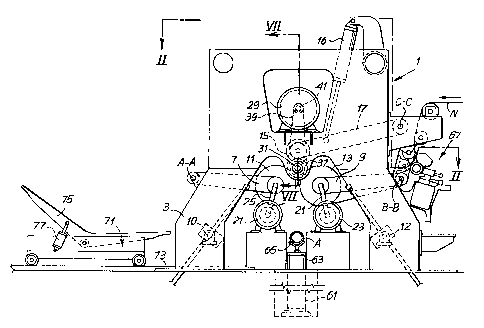
Fig. 1 shows a schematic side view of the machine according to the
invention;
Fig. 2 shows a plan view on I1-11 as marked in Fig. 1;
Fig. 3 shows a plan view of the withdrawal means for withdrawing
the winding mandrel;
Fig. 4 shows a front view on IV-IV as marked in Fig. 3;
Figs. 5 and 6 show views similar to those of Figs. 3 and 4 for a
larger-diameter mandrel;
Fig. 7 shows a partly sectioned view on VII-VII as marked in Fig. 1,
of the drive of the mandrel;
Figs. 8-11 show various conditions of the machine in side view
during the work cycle;
Fig. 12 shows a side view of a different mandrel drive system;
Fig. 13 shows a view on Xlil-XIII as marked in Fig. 12; and
Fig. 14 shows an enlarged section on XIV-XIV as marked in
Fig. 13.
Detailed Descriation of the Preferred Embodiment of the Invention
The machine, which is given the general reference 1, comprises a
pair of side frames 3, 5 between which are pivoted two pairs of arms 7, 9. The
pair of arms 7, pivoted about an axis A-A, carries a first lower winding roll
11,
while the second pair of arms 9, pivoted about an axis B-B, carries a second
lower winding roll 13. The two winding rolls 11, 13 are positioned side by
side
and define a winding cradle for the reel of weblike material, as will be
explained below. They can each be pivoted about their respective pivot axes
A-A and B-B by means of a threaded bar and nut system with the general
references 10 and 12, the threaded bar being hinged to its respective arm 7,
9. As an altemative, other types of actuators, such as cylinder-and-piston
CA 02273370 1999-05-31
-5-
actuators, can be used.
Above the two lower winding rolls 11, 13 is a third winding roll 15
carried by a pair of pivoting arms 17 hinged about an axis C-C to the side
frames 3, 5 of the machine. The number 16 denotes an actuator used to raise
and lower the roll 15.
The lower winding rolls 11, 13 are turned by two motors 21, 23
which (in the example illustrated) are set in fixed positions and connected to
the axes of the lower winding rolls 11, 13 by two constant-velocity joints 25,
27 (see Fig. 2). In this way the two lower winding rolls 11, 13 are free to
pivot
about the axes A-A, B-B. Alternatively, the motors 21, 23 could be supported
in line with their respective winding rolls 11, 13, or could be supported by
the
side frames 3, 5 coaxially with the pivot axes A-A and B-B of the arms 7, 9,
with a belt or equivalent drive to pulleys keyed to the shafts of the two
lower
winding rolls 11, 13.
Mounted on the side frame 3 of the machine is another motor 29
used to turn a mandrel 31 indicated by dots and dashes in Fig. 2, located in
an essentially fixed axial position such as to allow its insertion into a
tubular
core, or into a series of tubular cores lined up axially in the cradle defined
between the lower winding rolls 11, 13. Fig. 7 shows a partially sectional
view
of the mechanical connection (omitted in order to simplify the drawing in
Figs. 1 and 2) between the motor and the mandrel 31. The mandrel 31 is of
expandable type (known to those skilled in the art) and is inserted into a
sleeve 33 supported by bearings 35 in the side frame 3. Expansion of the
mandrel 31 locks it axially inside the sleeve 33. Keyed to the latter is a
pulley
37 carrying a belt 39 which takes its motion from the motor 29 via a drive
pulley 41. With this arrangement, when the mandrel 31 is not in its expanded
condition, it can be slid axially through the sleeve 33 for insertion into and
withdrawal from the winding zone defined between the lower winding rolls 11,
13 and the upper winding roll 15, while maintaining an essentially fixed axial
position.
Axial movement of the mandrel 31 is obtained with an arrangement
illustrated in Figs. 3 and 4 and omitted in order to keep the drawing clear in
CA 02273370 1999-05-31
-6-
Figs. 1 and 2. Hinged to the side frame 3 are two supports 43 supporting
respective geared motors 45 which drive two shaped rolls 47 covered in a
material with a high coefficient of friction, rubber for example. The two
supports 43 can be pivoted about respective hinges 49 by two cylinder-and-
piston actuators 51. In this way the two shaped rolls 47 can be moved either
into or out of contact with the cylindrical surface of the mandrel 31. When it
is
wished to move the mandrel 31 axially, the shaped rolls 47 are pressed
against the surface of the mandrel and rotated by the geared motors 45.
As can be seen by comparison of Figs. 3, 4 and 5, 6, the system
can easily be adapted to mandrels 31 of different diameters, Figs. 5 and 6
showing a mandrel of larger diameter than that shown in Figs. 3 and 4.
Lower down, beneath the lower winding rolls 11, 13 and partly
underneath the surface on which the machine 1 stands is a winding core
introducing means schematically depicted by a cylinder-and-piston system 61
whose rod 65 carries a V section. The tubular cores A (see Fig. 1) are placed
on the V section from the exterior by an insertion movement parallel to the
axis of the tubular cores.
The number 67 is a general reference for a system of adjustable
blades located in the inlet zone where the weblike material N enters the
machine 1. The blades are of a type known per se and will not be explained in
further detail here.
On the output side of the machine 1 is a carriage 71 traveling on
tracks 73 ending under the first lower winding roll 11. The carriage 71 is
equipped with a pivoting cradle 75 designed to take the reels formed by the
machine 1. Its pivoting is controlled by an actuator 77. The pivoting cradle
75
can be raised and lowered vertically to receive reels of varying dimensions.
The operation of the machine will be described below with
reference to Figs. 8-11. Shown in Fig. 8 is the condition of the machine at
the
start of the winding cycle. A new tubular core A, or a series of axially
aligned
tubular cores A, has been inserted into the winding cradle and the lower
winding rolls 11, 13 are in their highest position, while the upper winding
roll
15 is in its lowest position. The three rolls 11, 13, 15 are therefore in
contact
CA 02273370 1999-05-31
-7-
with the winding core or cores. The winding mandrel 31 has been inserted into
the tubular cores and expanded so as to grip them. The rotation of the
mandrel 31 by the motor 29 and the rotation of the lower winding rolls 21, 23
causes rotation of the tubular cores, on which a line of glue has previously
been applied, in order that the starting end of the weblike material N will
stick
to them. The latter reaches the winding zone already cut by the blades 67 into
longitudinal strips, so that one strip of weblike material is wound onto each
of
the tubular cores positioned on the mandrel 31. If it is wished to produce a
single reel of large axial dimension, the weblike material N may reach the
winding zone without first being cut. In this case one tubular winding core is
placed on the winding mandrel 31.
As the reel or reels of weblike material increase in diameter, the
lower winding rolls 11 and 13 are lowered by pivoting them about the axes
A-A and B-B, by means of the threaded rod and nut actuators 10, 12. In a
similar way the upper winding roll 15 is gradually raised by the actuator 16.
In
this way the axis of the developing reel is kept essentially stationary and
coinciding with the axis of rotation of the mandrel 31. The gradual lowering
and separating of the lower winding rolls 11, 13 increases the base on which
the reel is supported during its formation, thereby giving it greater
stability.
Fig. 9 shows the condition of the machine when the winding cycle
has been completed and the reel R has reached its final diameter. The lower
winding rolls 11, 13 are in their lowest position, while the upper winding
roll 15
is in the raised position. At this point the reel R must be unloaded onto the
cradle 75 of the carriage 71, the weblike material must be cut transversely to
generate a new free end, and a new tubular core or new series of tubular
cores must be inserted into the winding zone.
For this purpose the carriage 71 is brought up to the machine 1 by
a movement in the direction shown by the arrow f71 (Fig. 9) along the tracks
73, and its top part, on which the cradle 75 is hinged, is raised to the
position
shown in Fig. 10. The mandrel 31 is reduced in size and withdrawn from
inside the tubular cores A on which the reel R has been formed.
The lower winding roll 13, i.e. that furthest from the carriage 71, is
CA 02273370 1999-05-31
-$-
pivoted up about the axis B-B while the upper winding roll 15 may if desired
be moved further upward to facilitate the unloading of the reel R. In this way
the reel R is unloaded from the cradle 75 by rolling it in the direction of
the
arrow fR over the lower winding roll 11. In the meantime a new series of cores
A, provided with a line of glue applied in a manner known per se, has been
placed in readiness on the section 65 of the core introducing means.
During unloading of the finished reel and insertion of the new cores
A into the winding zone the weblike material has basically ceased to be fed
in,
except for a very small amount of material necessary to allow the reel R to
roll
into the tilting cradle 75 without tearing the weblike material.
fig.11 shows the next stage, in which the reel R has been
unloaded onto the cradle 75, and the latter has been pivoted by the actuator
77 and lowered back down. The lower winding roll 13 has again been lowered
from the position of Fig. 10, for the purposes described later, the lower
winding roll 11 is still in the down position and the upper winding roll 15
has
been moved back down. A cutting system mounted on the pivoting arms 17 of
the roll 15 can at this point cut the weblike material N transversely, between
the reel R and the lower winding roll 13. The cutting means (not shown) may
for example comprise a system of air nozzles, a retractable blade or other
means known per se or otherwise within the capabilities of those skilled in
the
art. Alternatively the material may also be cut by means arranged differently
but known per se.
The lowering of the lower winding roll 13 from the position of
Fig. 10 to that of Fig. 11 allows the introducing means 63 of the cores A to
be
moved upward so that the V section 65 positions the new cores A in the
winding zone, in line with the mandrel 31. To facilitate the introduction,
without
excessively lowering the roll 13, provision may be made for the introducing
means 63 to have a stroke inclined to the vertical.
Once the cores are lined up with the mandrel, the mandrel is
inserted axially into the tubular cores so that the introducing means 63 can
then be lowered. Once the tubular cores have been raised above the lower
winding roll 13 and the introducing means 63 retracted, the winding rolls 11,
CA 02273370 1999-05-31
-9-
13 can be raised again to return to the position of Fig. 8.
Lifting the cores into the winding zone may pinch the weblike
material between the cores and the upper winding roll 15, and possibly also
cause the weblike material to stick to the tubular cores because of the
applied
glue. At this point the position shown in Fig. 8 has been reached once again
and a new winding cycle can be commenced.
Cutting may conveniently be synchronized with the movements,
described above, of the rolls 11, 13 and of the introducing means 63.
Figs. 12-14 show a different embodiment of the mandrel withdrawal
and insertion device. These figures show an arrangement in which the
mandrel and its associated insertion and withdrawal system are mounted on a
vertically mobile slide. This enables this withdrawal system also to be used
in
a machine in which the lower winding rolls 11 and 13 are of fixed axis. The
withdrawal and insertion device constructed as in Figs. 4 and 5 could likewise
be mounted on a raising and lowering system, for the same reasons.
In the embodiment shown in Figs. 12-14 the mandrel, still
numbered 31, is inserted axially into a sleeve still marked 33 and supported
by bearings 135 in a housing 137. Fixed to the latter is a plate 139
supporting
two horizontal guides 141. On these guides two slides 143 move in opposite
directions along the guides 141 as shown by the arrow f143 (Fig. 13). The
translational motion is provided by a motor 145 via a threaded bar 147.
Mounted on each slide 143 is a pneumatic or hydraulic motor 151
providing motion to a respective shaped roll 153 equivalent to the shaped roll
47. The operation of the insertion and withdrawal device described above is
similar to that of the device shown in Figs. 4 and 5. The shaped rolls 153 are
pressed, by the motor 145, against the cylindrical surface of the mandrel 31,
and rotation in either direction by the motors 143 causes withdrawal or
insertion of the mandrel relative to the winding zone.
Also shown in Fig. 12 is a supporting roll 155 mounted idly on a
projecting bracket 157. This roll serves as a support for the mandrel 31 when
the latter is drawn out of the winding zone by the shaped rolls 153. The
number 171 indicates a mating center able to move vertically up and down
CA 02273370 1999-05-31
-10-
guides 173 on the opposite side frame from that where the shaped rolls 153
are located. The mating center holds the unsupported end of the mandrel 31.'
Compared with the embodiment illustrated in Figs. 3 and 4, the
embodiment of Figs. 12-14 is characterized by a reduction in the size and
weight of the shaped rolls.
This makes simpler any movement in a vertical direction of the
complete assembly made up of the shaped rolls, their associated drives and
the support of the mandrel 31. In Figs. 12-14 this assembly of mechanical
members is mounted on a carriage 161 capable of vertical movement
indicated by the double arrow f161 up and down vertical guides 163 fixed to
the side frame 165 of the machine. In this way the mandrel 31 insertion and
withdrawal device can also be mounted on rewinding machines in which the
lower winding rolls 11, 13 have fixed axes. For these machines the possibility
is not ruled out of also using a configuration of the type illustrated in
Figs. 4, 5
and 6, although that of Figs. 12-14 is more advantageous owing to its reduced
size and weight.
With an insertion and withdrawal device of this type it is possible to
construct a rewinding machine for the production of reels of wound weblike
material, of the type that comprises in combination: a pair of lower winding
rolls defining a winding cradle and means for inserting an axial mandrel into
said winding cradle. The means for inserting the mandrel comprise a pair of
shaped rolls with actuators which move said shaped rolls into contact with the
outer surface of the mandrel and with other actuators that rotate one or both
of the shaped rolls in order to move the mandrel parallel to its own axis, in
such a way as to give this mandrel alternate movements of insertion into the
winding cradle and withdrawal from the winding cradle. If the winding rolls
have fixed axes the mandrel insertion and withdrawal means are vertically
movable in order to follow the growth of the reel as it develops on the rolls.
It will be understood that the drawing shows only an illustrative
embodiment purely by way of a practical demonstration of the invention, which
invention may be altered in its shapes and arrangements without thereby
departing from the scope of the concept on which the invention is based. The
CA 02273370 1999-05-31
-11 -
presence of any reference numerals in the attached claims is for the purpose
for facilitating the reading of the claims with reference to the dravrings
arid
does not limit the scope of protection thereof.