Note: Descriptions are shown in the official language in which they were submitted.
CA 02273738 1999-06-08
ARK: jsg061698/7301027.APP UCC-1041
DEVICE FOR HOLDING A PLURALITY OF CONTAINERS
Field Of The Invention
The present invention is directed to a device for holding a plurality of
containers such as gallon containers for holding liquids or solids such as
household
cleaning products. The device is constructed with a pair of side support
sections
which provide sufficient support to hold the containers while allowing greater
visibility
of the containers and greater ease in removing the containers from the device
even
when the devices are stacked one upon the other.
Backgiround Of The Invention
Devices for storing and displaying containers of liquid or solid products,
especially household products such as cleaning fluids, bleach and the like are
known in the art. The devices typically comprise a base with upwardly
extending
sidewalls to provide support at opposed sides of the device. There is also
provided
an insert within the container that is used to provide additional support.
The typical insert is in the shape of the letter ~H° and includes
panels which
extend from opposed sides of the device to thereby form storage compartments
for
the individual containers. This type of design suffers from two major
disadvantages.
First, because the panels extend from one side of the device to the other, a
portion
-1-
CA 02273738 1999-06-08
ARK:jsg061698/7301027.APP UCC-1041
of the storage area is blocked from view. Therefore, even if a portion of the
sides of
the device are removed a consumer looking through the exposed portion of the
side
may see less than all of the containers or may not see any containers even
though
several containers may still remain within the storage area.
The second disadvantage of the "H" insert is that the containers cannot be
easily removed from the side of the device. Instead, the containers must be
removed from the top of the device. This reduces access to the containers
because
the user must be able to get above the device to remove the containers stored
therein especially relatively heavy containers such as gallon containers of
liquid or
solid product. In addition, the removing of the containers by consumer is
rendered
much more difficult and cumbersome.
As previously indicated, the conventional "H° insert is customarily
employed in
such devices because it adds significant structural strength to the device so
that the
same can be stacked without damage and can safely undergo the rigors of
shipping.
It would therefore be a significant advance in the art of storage devices,
especially storage devices for storing and displaying containers of liquid or
solid
products if a strong storage device could be fabricated which enabled
visibility of the
stored containers while enabling removal of the containers through the sides
of the
storage device.
-2-
CA 02273738 1999-06-08
ARK:jsg061698/7301027.APP UCC-1041
It would be a further advance in the art of storage devices to provide a
device
which can be easily stacked one upon the other during shipment and/or for
displaying the contents therein for consumer purchase.
It would be a further significant advance in the art of storage devices,
particularly for containers storing liquid orsoiid products, if the "H°
type insert could
be eliminated without sacrificing the structural integrity of the device.
Summary Of The Invention
The present invention is generally directed to a device for storing
containers,
typically containers of any shape or size for housing liquid or solid
commercial
products such as household cleaners, so that the same may be safely stored and
displayed. In accordance with the present invention, the storage device
provides
structural integrity so that devices filled with containers can be stored one
on top of
the other and provide a convenient display as well as ready access to the
containers
to facilitate purchase by the consumer.
More specifically, the present invention is directed to a device for holding a
plurality of containers comprising:
(a) a base having a floor portion and first and second opposed pairs of
walls extending upwardly from the floor portion;
-3-
CA 02273738 1999-06-08
. . r
ARK:jsg061698/730102?.APP UCG1041
(b) opposed side support sections extending upwardly from the floor, each
of said support sections comprising a back portion secured against one of the
walls
of the first pair of opposed wails and respective side port'ons secured
against a
portion of the respective walls of the second pair of walls, said base and
said
opposed side support sections defining a storage area for said containers; and
(c) an inwardly facing projection extending inwardly into the storage area
from each of the back portions.
The device of the present invention can be constructed in a variety of shapes
to accommodate a plurality of containers. The device may be provided with a
platform or cover to enable one device to be placed upon another for storage
and
display purposes.
Brief Description Of The Drawings
The following drawings in which like reference characters indicate like parts
are illustrative of embodiments of the invention and are not intended to limit
the
invention as described herein.
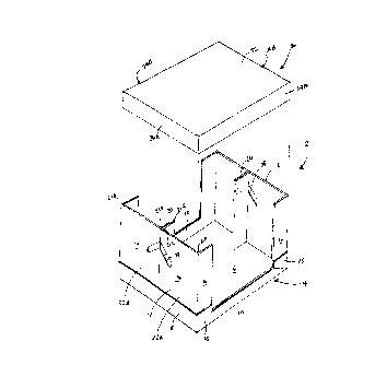
Figure 1 is an exploded perspective view of one embodiment of the device in
accordance with the present invention;
-4-
CA 02273738 1999-06-08
ARK:jsg061698/7301027.APP UCC-1041
Figure 2 is a plan view of the embodiment of the invention shown in Figure 1;
Figure 3 is a side view of the embodiment of the invention shown in Figure 1;
and
Figure 4 is a perspective view of another embodiment of the device of the
invention.
Detailed Description Of The Invention
Referring to the drawings and particularly to the embodiment shown in
Figures 1-3, there is shown an embodiment of the present invention in which
the
device 2 includes a base 4 having a floor portion 6, a first pair of side
walls 8 (only
one side wall is shown) and a second pair of side walls 10.
Attached to the first pair of side walls 8 are respective side support
sections
12 comprising a back portion 14 and opposed side portions 16. The side support
sections 12 are secured against and are contiguous with the first pair of the
side
walls 8 and a portion 18 of the second pair of side walls 10.
In accordance with the present invention, extending inwardly into the storage
area from the back portion 14 is an extension 20 which provides additional
support
-5-
__ CA 02273738 1999-06-08
ARK:jsg061698/7301027.APP UCG1041
for the device, yet does not take up nearly as much room or interfere with the
line of
sight into the device as the prior art "H" type of insert
The extension 20 may be constructed separate from the back portion 14 and
then attached thereto by mechanical means such as staples or the like or by
adhesive means such as by glues, adhesives and the like suitable for bonding
the
back portion 14 and the extension 20 together. The adhesive means suitable for
this purpose would be known to those skilled in the art.
In a preferred form of the invention the entire side support sections
including
the-extension are constructed from a single piece of material such as
corrugated
board. Referring specifically to Figures 1 and 3, the side support sections 12
comprising the back portions 14, the side portions 16 and the extension 20 are
constructed from a continuous, single piece of material. As gleaned from
Figure 1, a
blank is folded or molded to have comers 21A and 21B connecting the respective
side portions 16 to the back portions 14. Comers 29 C and 21 D are provided to
connect the back portions 14 to the extension 20. The extension 20 is
completed by
folding the material used to construct the back portion 14 upon itself at the
point
21 E. As a result, the component parts of the side support sections 12 are
integral
which adds strength to the device over construction in which the component
parts
are constnrcted separately and connected through mechanical and/or adhesive
means.
-6-
CA 02273738 1999-06-08
r'
ARK:jsg061698/7301027.APP UCC-1041
As best shown in Figure 1, the back portion 14 can be formed from two
components 22A and 22B. In a prefen-ed form of the invention two adjacent side
portions 16 of the respective components 22A and 22B are secured together such
as by gluing to form the inwardly extending extension 20. The extension 20
itself
can be glued to the floor 6 of the device to provide additional structural
integrity for
the device 2.
The side support sections 12 are positioned only in proximity to the first
pair
of side walls 8. The second pair of side walls 10 do not have side support
sections
and therefore provide a line of sight from either side of the device into the
storage
area. Side support sections are not needed for the second pair of side walls
10
because the side support sections 12 provide sufficient strength and support
for the
device even for storing and displaying relatively heavy containers of liquid
or solid
product.
The device 2 of the present invention may be provided with a cover which can
serve a dual purpose. First, the cover provides a flat surface enabling
another such
device to be placed upon the cover to stack one device upon another. A second
advantage of the cover is to provide a means for protecting the containers.
Referring to Figure 1, a cover 30 is shown having a top side 32 and a pair of
opposed sides 34A and B and 36A and B. The cover is dimensioned so that it,
-7-
CA 02273738 1999-06-08
ARK:jsg061698/7301027.APP UCC-1041
preferably, fits over and snugly nestles about the side support sections 12 of
the
device. When the cover 30 is included as part of the device, the top side 32
provides a flat surface upon which another such device can be placed thereon
to
provide a stacked series of devices each containing a plurality of containers.
The
presence of the side support sections 12 and the inwardly extending extension
20
provide the requisite structural integrity to enable the devices to maintain
their shape
and to protect the containers therein when stacked one upon the other. It will
be
understood that the cover can have a variety of shapes which would be apparent
to
those skilled in the art.
The device 2 may be provided with some means for facilitating the carrying of
the device, especially when loaded with a plurality of containers. For
example, as
specifically shown in Figure 1, the device 2 has in the respective back
portions 14,
an opening 38 of sufficient size and shape to enable a person to effectively
insert
their hand within the device. The shape of the opening 38 can be tailored to
fit the
palm of the user.
As shown in Figures 1-3, the shape of the device is rectangular. The device
can also be made in the shape of a square or in the shape of a polygon as
described hereinafter.
_g_
CA 02273738 1999-06-08
ARK:jsg061698/730102T.APP UCC-1041
In another embodiment of the invention, the device 2 can be formed in the
shape of a polygon such as an octagon as specfically shown in Figure 4. As
shown
in Figure 4, the device 2 includes respective side support sections 12 each
comprised of respective back portions 14 and an inwardly extending extension
20 as
described in connection with the embodiment of Figures 1-3.
In the present embodiment, the side portions 16 are comprised of two panels
16A and 16B. The panel 16B is contiguous with the side wall 10 while the panel
16A provides a connection between the panel 16B and the back portion 14. The
panel 16B lies at an angle with respect to panel 16A and back portion 14 and
thereby provides the additional sides necessary to give the device an
octagonal
shape.
The modification of the side support sections 12 shown in Figure 4 is
accommodated by a similar modification to the side walls. In particular, the
portion
18 of the side walls 10 is divided into a first portion 18A which is
contiguous with the
panel 16A and a second portion 18B which is contiguous with the panel 16B
described above. As a result, the side sections 12 and the side wails 10 are
closely
aligned in a supporting relationship to provide structural integrity to the
device.
It will be understood that other shapes may be employed in accordance with
the present invention depending, in part, on the number and shapes of the
_g_
CA 02273738 1999-06-08
ARK:jsg061698/7301027.APP UCC-1041
containers to be stored within the device. The size of the device may be
varied
depending on the size of the containers. Accordingly, the device of the
present
invention can be used to store containers containing, for example, liquid or
solid
household products, automotive products, food products and the like. The shape
of
the container which can be stored by the present device can vary widely and
include
round containers, polygon shaped containers and irregular shaped containers.
The device 2 may be constructed of a variety of materials including but not
limited to paper based products such as corrugated board; plastics;
composites;
metals and the like. In the case of paper-based products, for example, the
device
can be fabricated from precut blanks as is customary in the corrugated
container
industry. Alternatively, the device may be formed from a mold such as when the
construction material is a plastic. Other methods of manufacturer would be
apparent
to those of ordinary skill in the art.
-10-