Note: Descriptions are shown in the official language in which they were submitted.
CA 02273889 1999-06-09
Title: Glove or mitt principally for use as a catchincr glove by
ice hockey goalkeepers
Background of the Invention.
l.Field of the Invention
The present invention relates to a glove or mitt
principally for use as a catching glove by goalkeepers in games
such as ice hockey. For convenience, the term "glove" will be
used herein, as it is common parlance, even though such gloves
may only have one pocket for the player's four fingers.
The glove of this invention allows a sports implement such
as a hockey stick, or the handle of other sports implements,
such as a tennis racquet, or of a tool, to be held without the
player using his thumb, and accordingly it may also be useful
for players of various games, and for workers, needing to hold
such handles when a thumb is missing or disabled.
2.Prior Art
In the game of ice hockey, goalkeeper's hands require
considerable protection since it is necessary for these to
catch or deflect hard pucks which travel very fast . For the
catching hand, which may be the right or left hand, gloves have
been used which are basically similar to those used in
baseball , having a padded f finger pocket or pockets and a padded
thumb pocket connected by webbing which spans the gap between
these pockets, and which is used to catch a puck. However,
unlike with baseball gloves, hockey goalkeeper's catching
gloves also have to allow the goalkeeper to hold and manipulate
a hockey stick, and in the known construction the gloves often
1
CA 02273889 1999-06-09
have too much padding and are too stiff to allow good stick
handling, especially if the goalkeeper does not have strong
hands.
There have been a number of past attempts to improve on
the ability of a hockey goalkeeper' s catching glove properly to
grasp his hockey stick. These efforts all have one or more
critical drawbacks, such as compromising the glove or
goalkeeper's catching ability, adding too much weight, being
too complicated with too many moving parts increasing the
likelihood of breakdown, or failing to provide a quick and sure
grasp and release of the stick.
Specific prior art designs are described in the following
U.S. patents:
No.4,967,418 to Marcotte, issued Nov.6, 1990; and
No.5,435,008 to Shane, issued July 25, 1995.
Marcotte describes a glove having thumb and finger pockets
of generally conventional type, but having, on the outer or
back side of the finger pocket, an additional part for gripping
the stick. This is a so-called "gripping pocket", which is a
flexible pocket into which the fingers can be inserted. An
opening is provided connecting the usual finger pocket to the
gripping pocket, so that when the goalkeeper wishes to grip the
stick he can move his fingers from the finger pocket to the
gripping pocket and then use the fingers to hold the stick
between the inside of the gripping pocket and an outer side
portion of the collapsed finger pocket which is held against
the stick by the thumb. The drawback of this is that the
goalkeeper may need to move his fingers quickly from the
gripping pocket to the finger pocket in order to make a save,
and this may be awkward with this construction.
2
CA 02273889 1999-06-09
In Shane, the stick is held in the normal way, between the
finger pocket and the thumb pocket, but means are provided to
improve the grip on the stick. The means shown by Shane are
believed to add undesirable weight and restrict the catching
ability.
In both these prior patents, the thumb is needed to apply
holding forces to one side of the hockey stick, and accordingly
these constructions do not offer any solution to a player of
ice hockey, or of any other game, where the player has a
missing or disabled thumb.
Summary of the Invention
The present invention, like that of Marcotte, provides an
additional part at the outside of the finger pocket or pockets
(hereinafter the "finger pocket means") which can be used to
hold a stick against the outside of that pocket means . However,
with the present invention, the player's fingers stay in the
usual finger pocket portion of the glove, whether he is making
a save or handling the stick. The glove of this invention
allows the user to quickly and surely grip and release the
shaft of a hockey stick without compromising the glove's
ability to catch a puck, and without adding much weight. It
also allows the goalkeeper to shoot forehand, backhand, and to
"stickhandle", and even execute the "slapshot", all with the
same proficiency as a forward position player.
In accordance with the one aspect of the present
invention, a glove for use by a hockey goalkeeper, of the type
having finger pocket means and a thumb pocket and in which the
finger pocket means forms part of the glove body having an
outer side or back positioned to overlie the goalkeeper's
3
CA 02273889 1999-06-09
knuckles and having an inner or palm side, further comprises a
hockey stick retainer which overlies a portion of the said
outer side, the stick retainer being connected to control means
for controlling movement of the retainer away from the outer
side portion and having a stiffness such that, with the control
means acting on the retainer, a hockey stick can be held firmly
between the outer side portion and the retainer while all the
goalkeeper's fingers remain in the finger pocket means.
The glove of this invention effectively holds the stick
against the back of the catching hand, and does not require use
of the thumb for holding the stick. This feature makes the
glove suitable for players of other sports in which an
implement handle may need to be held without the use of a
thumb, and also for users of other implements or tools who lack
a usable thumb. More generally, therefore, in accordance with
this broader aspect of the invention, a glove for holding the
handle portion of a sports implement such as a tennis or
badminton racquet, or of a hockey stick or lacrosse stick, or
of a tool, and having finger pocket means with an outer side
overlying the user's fingers, also has a handle retainer which
overlies a portion of the outer side of the finger pocket
means, and is connected to control means as described above.
The control means may include spring means acting to pull
the retainer towards the outer side portion. The spring means
may be constituted by the resilience of the retainer, which may
be in the form of a resilient gripping plate.
Preferably, the control means include a stop member which
limits the movement of the retainer relative to a stiff plate
located at the inner or palm side of the finger pocket means,
and the finger pocket back or outer side is flexible to allow
4
CA 02273889 1999-06-09
the player's fingers to be bent so that the fingertips press
against the stiff plate while outwards movement of the finger
knuckles causes the outer side portion of the finger pocket
means to firmly grasp the stick or handle between itself and
the retainer. The stiff plate "located at" the inner or palm
side of the finger pocket means may be inside or outside the
finger pocket means. The control means may include a hollow
chamber attached to the stiff plate, and a stop member having
an inner end mounted for limited movement in the chamber and
having an outer end restricting movement of the retainer away
from the stiff plate.
Preferably, the control means are located in an area
between the second knuckles and finger tips of fingers placed
within the finger pocket means, and preferably are located
between the middle and ring fingers, and the retainer has an
additional connection to the body of the glove outwardly beyond
the finger tip position. The stiff plate may be part of a palm
plate forming the inner side or front of the body of the glove
and of the finger pocket means. The retainer may have two
spaced connections to the body of the glove both located near
the outer edges of the palm plate and outwardly beyond the
finger tip position. The control means may be associated with
a divider between two f finger pockets each of which accommodates
two of a player's fingers.
Unlike with Marcotte, the finger pocket means has no
aperture allowing the fingers to be moved out of the normal
catching position. Also, while in Marcotte the stick is
inserted under the fingertip end of the "gripping pocket", in
the present invention the entry of the stick into the retainer
is from the knuckle or wrist end of the hand.
5
CA 02273889 1999-06-09
Brief Description of the drawings.
Preferred embodiments of the invention will now be
described by way of example with reference to the accompanying
drawings, in which;
Fig.l illustrates a hockey goalkeeper assuming a shooting
posture while grasping the shaft of his stick by a right hand
glove incorporating this invention;
Fig.2 is an enlarged view of the glove showing the
relationship to the stick;
Fig.3 is a view similar to Fig.2 but in which the stick
retainer or "gripping plate" has been partly cut away;
Fig.4 is a generally horizontal section of the glove of
this invention, used on a player's right hand, and looking down
the axis of the stick;
Fig.5 is an enlarged, partly sectional view of the side of
control means of the gripping plate which limit outward
movement of the this away from the finger pocket, the control
means being shown extended;
Fig.6 is a further view of the control means in a
retracted position, viewed parallel to the finger direction:
Fig.7 is a perspective view of a hollow chamber part of
the control means,
Fig.8 is a bottom end view of the same part;
Fig.9 is an inside view of the gripping plate;
Figs. l0 to 12 are views similar to Fig.4, showing
successive positions of the hockey stick as it is inserted into
the retainer or gripping plate of the glove;
Fig. l3 shows an alternative embodiment of gripping plate;
Fig.l4 shows an alternative palm plate for attachment to
the inner surface of a glove body;
Figs.l3A and 14A are fragmentary, partly sectioned views
of portions of the gripping plate and parts of the control
6
CA 02273889 1999-06-09
means connected thereto; and
Fig.l5 is a fragmentary view of part of what is shown in
Fig.4, but with an alternative arrangement of control means.
Detailed Description.
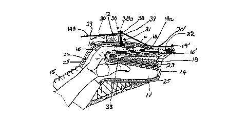
_5 Fig.l shows a goalkeeper using a catching glove indicated
at 10 on his right hand to hold the shaft or handle 12 of a
hockey stick, the stick being held onto the back or outside of
the finger portion of the glove by a retainer or gripping plate
14.
_10 As shown in more detail in Figs. 2 and 3, a main part of
the glove is conventional in having a cuff 15, and is similar
to a baseball mitt in having a f finger pocket means 16 and a
thumb pocket 17. These finger and thumb pockets are connected
by webbing 18 which allows the user to catch a puck. The ffinger
15 pocket means 16 has two pockets each accommodating two of the
player's fingers, the finger pockets forming a part of the
glove body 16'. This glove body has lacing 19 at an outer rim
and additional lacing 20 along an inner seam roughly parallel
to and spaced within the outer rim.
_20 The inner side or front of the finger pocket means 16 and
glove body 16', facing the thumb pocket 17, is covered with a
protective palm plate 22. This extends out beyond the ends of
a player's fingers by an amount slightly greater than a finger
length, to the outer edge of the glove body. The inner side of
_25 the thumb pocket has a thumb plate 23 facing the palm plate 22;
these plates provide additional protection when the player is
catching a puck. All these areas of the glove are covered by
padding 24, which itself is covered by a leather outer covering
25.
7
CA 02273889 1999-06-09
Figs.2 to 9 show details of the hockey stick retainer, and
control means for the retainer, in accordance with the
invention.
The stick retainer is in the form of a "gripping plate" 14
of shatter proof plastic having a shape shown in Figs.2 to 4
and 9. The plate has a narrow end portion 14a which is tightly
secured to the outer side of the glove body 16' by parts 19'
and 20' of the lines of stitching or lacing 19 and 20, at fixed
locations respectively near the curved outer rim of the palm
plate and spaced within this rim, so that the secured end of
the gripping plate is substantially rigid with the palm plate.
As seen in edgewise view, for example in Fig.4, when the
gripping plate 14 is deployed to hold the stick handle 12, the
narrow portion 14a on the knuckle side of the fixed locations
19' and 20' is bowed outwardly from the glove body to leave a
clearance space at the outer side of the finger pocket means
16. As seen in front view, Fig.2, plate 14 also broadens
laterally into portion 14b, and this portion retains the stick
12 at about its longitudinal center. On the fingertip side of
this center is an aperture which receives the outer end of a
stop member 36 which is part of control means 31 shown best in
Figs.4 to 8 and described below. As seen in Fig.4, just to the
finger tip side of the stop member 36 the gripping plate
portion 14b is slightly bent inwardly so that, when the plate
is separated by stick 12 from the outer side portion 16a of the
finger pocket means it is roughly parallel to this outer side
portion. The inner surface of the gripping plate portion 14b,
as shown in Fig.9, has a high friction, rubberized area shown
at 29 which is opposite the outer side portion 16a of the
finger pocket. The outer side portion 16a and area 29 between
them constitute a gripping zone 30. This glove outer side
8
CA 02273889 1999-06-09
portion may have a rubberized area for better holding of the
stick.
The gripping plate is resilient, and when unstressed lies
close to the outer surface of the glove body 16', as indicated
in Fig.lO.
Referring to Figs.4 to 8 showing the control means 31,
these include a hollow base part 32 which passes through an
aperture in the palm plate 22 and terminates in a flange 33
attached to the outside of this palm plate. This base part 32
is oval in cross-section, as shown in Fig.B, being elongated in
the direction of a user's fingers so as to be accommodated
within a divider which separates the two pockets of the finger
pocket means 16, and which fits between the middle and ring
fingers of the player, usually at a location between the second
_15 and third knuckles of the fingers. Base part 32 has an
elongated chamber in which is slidable the enlarged inner end
34 portion of a bushing 35 forming part of the movable stop
member 36. Bushing 35 has a narrow outer portion which can
slide through an outer end aperture 32a in the housing until
_20 the inner end portion 34 meets the inside top of the chamber.
The bushing 35 houses a threaded portion of an adjustable screw
38 which passes through the gripping plate portion 14b and
terminates in a head 38a on the outside of the gripping plate,
this plate being held between the head 38a and a nut 39 inside
25 the plate. The parts 35, 38 and 38a form parts of the movable
stop member 36. Instead of the nut 39, a snap washer may be
used.
As will be apparent from Fig.4, the arrangement is such
that when the user's fingers are bent, with his finger tips
30 pushing against the rigid palm plate 22 (through the
9
CA 02273889 1999-06-09
intermediary of the inside of the finger pocket means), the
outwards movement of the knuckles pushes out the outer side
portion 16A of the finger pocket 16, and traps the hockey stick
12 between this outer side portion and the high friction
_5 surface 29 of the gripping plate, the outwards movement of
which is limited by the head 38a of the stop member 36. The
screw 38 can be adjusted in the bushing 35 to suit different
player's hands.
Figs. l0 to 12 show stages in the insertion of the stick
_10 into the gripping zone 30 under the gripping plate 14. In
Fig.lO, the gripping plate is resting against the outer surface
of the finger pocket 16 means, with the stick 12 being inserted
under the free edge of the gripping plate which provides an
insertion area. Immediately upon contact with the stick 12 the
15 plate 14 rises to accept the stick. Fig.ll shows the next
stage, where the stick is being slid between the pocket outer
surface and the gripping plate, into the gripping zone 30.
Fig.l2 shows the final position, in which the fingers are
slightly bent so that the knuckles push out the outer surface
20 portion 16a while the high friction surface 29 of the gripping
plate is pulled against the stick, holding it firmly.
The stick is easily released in the follow through of any
shooting or stick handling manoeuvre by a slight inward or
outward rotation of the wrist.
_25 While the control means as described is practical, the
invention is not limited to this specific control means. For
example, the control means may comprise a simple or composite
spring connection between the gripping plate and the palm
plate, or a resilient gripping plate having suitable
30 connections to a rigid palm plate, may also be used.
CA 02273889 1999-06-09
In addition, instead of a single stop member positioned
between the fingers, a pair of stop members may be used, each
including one of a pair of hollow chambers situated on outer
sides of the user's four fingers.
_5 As mentioned above, the basic parts of the invention can
be used in many other circumstances where it is required for a
hand with a disabled thumb, to hold the handle of a sports
implement or a tool. Clearly, in many such cases, the glove
will not need any thumb pocket, and the term "glove" should be
_10 understood as referring to merely the essential parts of the
invention, namely the finger pocket means, handle retainer, and
control means acting on the retainer.
Figs. 13, 13A, 14 and 14A show alternative means of
connecting control means to a gripping plate and palm plate,
15 which allows for adjustment of the connection point.
As shown in Figs.l3 and 13A, a gripping plate 114 has a
slot 142 with generally parallel sides, the sides having a
series of opposed notches 143. This slot receives an adapter
member 140 which includes a large outer washer portion 144 held
20 by the screw head 38a. The adapter member 140 is held between
a large diameter nut 139 and the screw head 38a, the nut 139
and washer portion 144 being large enough to overlap portions
of the gripping plate 114 at the sides of the slot 142. The
member 140 has an inner portion 145 with each of its opposite
_25 sides formed with a pair of spaced protrusions 145a which fit
into selected notches 143. The portion 145 is short relative to
the slot 142 and can be fitted into the slot at different
positions along the slot, as required to adjust the parts, for
comfort of grip, to different lengths of fingers, being secured
30 by pressure between inner nut 139 and outer washer portion 144
11
CA 02273889 1999-06-09
on the inner and outer sides of the gripping plate.
Figs.l4 and 14A show a similar adjustability for the
connection between the palm plate 122 and the hollow base part
132 corresponding to part 32 previously described. As shown,
the palm plate has a slot 150 similar to slot 142, and the base
part 132 is formed with protrusions 132a which can be fitted
into notches at the sides of the slot at several different
positions of the base part along the slot. The flange 133 at
the bottom of the base part is large enough to overlap the
sides of the slot 150, and holds the base part in place.
Fig.l5 shows a construction which is similar to that of
Fig.4, but in which the flange 33 of the base part 32, instead
of being mounted on the palm plate 22, is connected to a stiff
plate 222 which is inside the finger pocket means, and not
_15 attached to the finger pocket means. This plate has its outer
edge under the fingertip portions of the user's fingers, and
sufficiently far forward to be pressed down when the fingers
are bent as shown, so as to pull the stop member 36 inwardly.
It will be understood that the term "fingertips" includes these
end portions of the fingers.
12