Note: Descriptions are shown in the official language in which they were submitted.
CA 02273953 1999-OS-31
WO 98/26334 PCT/US97/20415
1
TIMEPIECE FOR SIGHT IMPAIRED INDIVIDUALS
' BACKGROUND OF THE INVENTION
The following invention relates to a
timekeeping device and, in particular, to a timepiece
having a visual design that allows sight-impaired
individuals to read the time accurately from the
timepiece.
Analog timepieces have been in use for hundreds
of years, but are particularly ill-suited for poor
sighted individuals and for normal sighted individuals
under circumstances of poor illumination, or where it is
desired to tell time with a quick glance. Typically,
analog timepieces include a housing divided into segments
with time intervals designated around the periphery and
synchronized with the rotation of "hands" that point to a
specific hour and/or minute. In order to achieve maximum
accuracy, the hands of analog timepieces are often
slender and difficult to discern by poorly sighted
individuals or by normal sighted individuals under poor
lighting conditions. Thus, poor sighted individuals have
difficulty reading traditional analog timepieces because
of the narrowness of the time indicators or hands even
when studying the device for a long period of time. The
same is true of normal sighted individuals under poorly
lighted conditions. The traditional analog timepieces
are therefore completely ineffective for allowing poor
sighted individuals to quickly and accurately determine
the time, and for allowing normal sighted individuals to
tell the time quickly and accurately under poorly lighted
conditions.
' Digital timepieces, especially wristwatches,
likewise do not allow poor sighted individuals to
accurately tell the time quickly, accurately or easily.
The numbers displayed on digital wristwatches are small
and may be difficult to read, even for those without
sight problems. In addition, some of the numbers
CA 02273953 1999-OS-31
WO 98126334 PCTlUS97I20415
2
displayed in a typical digital timepiece are easily
confused. For example, the numbers 3, 5 and 8 can be
similar in appearance in a typical digital display. A
poor sighted individual could easily mistake one of those
numbers for another with a quick glance, and often cannot
precisely determine differences in numerals even with a
prolonged look at the face of the timepiece.
While timepieces that utilize color and/or
design variation are well known in the industry, there is
no product that provides a reliable indicator of time for
sight-impaired persons. Lorello, U.S. Patent No. ,
5,422,864 uses color to indicate precise minutes, either
before or after the hour. Radal, U.S. Patent No.
4,945,522 discloses a timepiece that utilizes color to
optically suppress all information not necessary to
reading the time, but the color employed in Radal does
not relate to time interval identification at all. Maue,
U.S. Patent No. 4,206,592 discloses a timepiece that
utilizes color to aid in the identification of time
intervals. McMahon, U.S. Patent No. 4,006,588 discloses
a watch face that identifies the hour by an aperture
which displays a different color for each time interval,
and requires the user to learn or memorize the various
different colors for each interval.
Horzick, U.S. Patent No. 3,803,831 discloses
overlaid translucent rotary dial disks that indicate time
increments by a continually expanding zone of either
light or darker color. The boundaries of the regions of
darker or lighter colors are ambiguous, however, and it
is difficult to tell the time accurately.
SUMMARY OF THE INVENTION
The present invention is a timepiece that
depicts time intervals in such a way that it allows even
poorly sighted individuals to quickly and accurately read
the time. The invention uses disks having annular bands
or rings of graduated visual design density to form a
CA 02273953 1999-OS-31
WO 98/26334 PCT/US97/20415
3
sharp contrast zone between the area of greatest visual
design density and the area of least visual design
' density at the juncture of the two regions. The term
"visual design density" as used herein represents a
design intensity that may include coloration, lines, dots
or other design artifacts. In general, areas of greatest
design density are "darker" or more heavily shaded than
areas of lesser design density. Time intervals are
identified when the sharp contrast zone is aligned With
a
time indicator position such as the time indicator posi-
tions of a traditional analog timepiece (i.e., straight
up is 12 o'clock, 3 o'clock is 900 moving clockwise from
12 o'clock, straight down is 6 o'clock). The eye follows
the graduated visual design density to the point of the
greatest contrast which is easily readable by individuals
having poor eyesight or by normal sighted individuals
under poorly lighted conditions. Thus, the timepiece of
this invention indicates time intervals in the same
manner as a traditional analog timepiece, only using
visual design density contrast zones to indicate time
instead of the traditional "hands" of an analog
timepiece.
The invention employs a myriad of unique and
aesthetically appealing visual designs generally arranged
in rings or annular bands that are graduated from an area
of greatest visual design density to an area of least
visual design density to create a sharp zone of contrast
at the juncture of the two regions. This zone is
synchronized with time indicators to indicate time inter-
vats and thereby overcomes the difficulties of previous
methods of time indication-for poor sighted individuals.
' The present invention may have separate disks
for each time interval indicator, i.e., separate disks
for hours, minutes, seconds. Each disk has its own
graduation of visual design density and/or coloration,
and each may be different from the other. Each disk,
however, provides a sharp zone of contrast on each
CA 02273953 1999-OS-31
WO 98!26334 PCT/US97/20415
- 4
respective band and for each time interval indication
desired. The direction of preparation of the variable
design density can be the same for each disk or may be
different for one or more disks. The disks may be nested
and the innermost disk may provide a cavity for the
placement of a design artifact such as a jewel or
insignia. Alternatively, the disks interiority of the
band may be transparent to show the inner workings of the
timepiece.
The timepiece of the invention can also be
adapted to display a "clock" on a computer screen or
modified to serve as a constantly changing "screen
saver," occupying the entire computer screen.
Accordingly, it is an object of the present
invention to provide a timepiece that allows poor sighted
individuals to quickly and accurately read the time.
Another object of the present invention is to provide a
timepiece that allows normal sighted individuals to
quickly and accurately read the time even under poorly
lighted conditions.
It is an advantage of the present invention
that a timepiece is provided that is of such strikingly
novel design and functionality that it makes a novel
aesthetic statement, and is therefore desirable to be
used by individuals with no sight problems.
Yet another advantage is to provide a
timepiece which is of simple reliable and rugged
construction, yet economical to manufacture and maintain.
Yet another advantage is to provide a timepiece
that can be incorporated into other products such as
computer screen clocks and screen savers.
The foregoing and other objectives, features,
and advantages of the invention will be more readily
understood upon consideration of the following detailed
description of the invention, taken in conjunction with
the accompanying drawings.
CA 02273953 1999-OS-31
WO 98!26334 PCT/US97120415
BRIEF DESCRIPTION OF THE DRAWINGS
FIG. l is a top view of a timepiece employing
' the invention.
FIG. 2 is a top view of an alternative
. 5 embodiment of a timepiece employing the invention.
FIG. 3 is a side cutaway view taken along line
A-A of FIG. 1.
FIG. 4 is a side cutaway view of an alternative
embodiment of the invention employing a seconds
indicator.
FIG. 5 is a side cutaway view of a timepiece of
FIG. 2 taken along line B-B of FIG. 2.
FIG. 6 is a top view of an alternative
embodiment of the invention employing a spiral design.
FIG. 7 is a top view of an alternative
embodiment of the invention showing a large central
cavity.
FIG. 8 is a partial side cutaway view taken
along line C-C of FIG. 7.
DETAILED DESCRIPTION OF THE PREFERRED EMBODIMENT
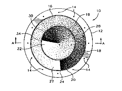
A timepiece 10 such as a wrist watch includes a
frame 12 having time indicator markings 14 spaced about
the periphery of the frame 12 in conventional hour posi-
tions as might be found on a typical analog timepiece. In
the embodiment of FIG. 1 the markings 14 indicate twelve
hours such as 12:00, 1:00, 2:00, etc. However, there
could be any number of such indicator markings and some
traditional analog time pieces provide only four of such
markings at the 12:00, 3:00, 6:00 and 9:00 positions. In
' addition, the markings could be arabic or roman numerals,
dots, slashes, jewels, artifacts or any other kind of
marking.
A first rotatable disk 16 includes a visual
design in an annular band or ring 18. The design about
the circumference of the band 18 has a visual design
CA 02273953 1999-OS-31
WO 98I2G334 PCTIUS97120415
- 6
density that proceeds from a region of highest design
density 20 to a region of lowest design density 22 so as
to form a sharp contrast zone 24 at the juncture of the
design density regions 20 and 22. The rotation of the
disk 16 is synchronized such that the sharp contrast zone
24 periodically aligns with the time indicator markings
14 to indicate a component of time (i.e. hours, minutes
or seconds). Because the variable design density is
spread over the entire radial width of the band or ring
18, a sight impaired person can easily discern the loca-
tion of the sharp contrast zone and thereby be able,to
perceive its location relative to the time indicator
markings 14.
A second rotatable disk 28 located radially
inwardly of the first rotatable disk 16 also includes a
band 19 (which in this case occupies substantially the
entire disk) with a design having a variable design
density and includes a first region of most dense visual
design density 30 that is continuously graduated in a
clockwise direction to a region of least design density
32 thereby forming a second sharp contrast zone 34 at the
juncture between the two regions 30 and 32. The variable
design density in the bands 16 and 19 is shown in FIG. 1
as a collection of dots or speckles but could be any
visual design including variations in color intensity.
If color is used, the area of greatest design density
will be perceived as a "dark" region or region of most
intense color and the region of least design density will
be perceived visually as a "light" region or one of
lightest coloration.
Referring to FIG. 3, the rotatable disk 16 is
included within the frame 12 covered by a watch crystal
11 which may be constructed along the lines of a conven-
tional wrist watch. The disk 16 is supported on a
central post 36 which is driven by a drive machine 38.
The disk 28 is supported by a post 40 which is concentric
to the post 36. Conventionally, disk 16 would be driven
CA 02273953 1999-OS-31
WO 98,/26334 PCT/US97/20415
7
by the drive machine 38 so that it would make a complete
rotation once every hour by appropriate gearing in the
' drive machine 38 (not shown). Synchronization may be
accomplished in the conventional way by rotatably adjust-
ing the disk 16. The disk 28 could be driven by post 40
so that it makes one complete revolution every twelve
hours so as to indicate hours in the conventional manner.
In order to provide a pleasing and aesthetic visual
impression, the disk 28 may be nested within a recess 17
in disk 16 so as to form a substantially planar surface
appearance when viewed by the user. Preferably the bands
18 and 19 should be opaque if the disks are to be nested
so that there is no confusion regarding the relative
positions of the sharp contrast zones 34 and 24.
The embodiment of FIG. 2 is in all respects
similar to the embodiment of FIG. 1 with the exception
that the inner rotatable disk 42 includes a recess or
cavity 44 into which a decorative artifact 46 may be
placed. The decorative artifact 46 could be a jewel or
an insignia or an emblem and could either remain fixed
or
could rotate with disk 42. As shown in FIG. 2 the recess
44 is an integral part of the disk 42 so that the arti-
fact 46 rotates with disk 42. Alternatively the artifact
46 could be supported on a stationary inner post (not
shown) through an aperture in the center of disk 42 so
that it remained stationary at all times.
An embodiment of the invention showing
rotatable disks for indicating minutes, hours and seconds
is shown in FIG. 4. A frame 50 includes a drive machine
52 having output posts 54, 56 and 58 which rotatably
support disks 60, 62 and 64, respectively. It should be
' understood that the disks 60, 62, and 64 include annular
bands or rings similar to those shown in FIGS. 1 and 2
employing a design having a variable design density which
proceeds around the circumferences of each band over
substantially the entire width of each to create a sharp
contrast zone between regions of highest visual design
CA 02273953 1999-OS-31
WO 9826334 PCT/US97/20415
8
density and regions of lowest visual design density. The
disks 60, 62 and 64 are geared in the drive machine 52 to
indicate hours, minutes and seconds. It is not critical
to the invention as to which disk is chosen to represent
which time indication, as this may be a matter of
aesthetic or design choice. The disks 60, 62 and 64 are
nested as provided in recesses 66 and 68 so as to present
to the viewer a substantially planar surface. The mech-
anism including the disks is protected by a conventional
watch crystal 70.
A different aesthetic design is shown in
FIG. 6. Mechanically FIG. 6 is similar to the design of
FIG. 1 with the exception that the design is shown as a
spiral pattern. An outer annular band or ring 72 has a
radial line pattern that spans substantially the entire
width of the hand 72 to thus create a zone of highest
design density 74. The lines grow progressively shorter
in a counterclockwise direction around the band 72 to
create a visually pleasing spiral pattern narrowing to a
vanishing point at a region of least visual design
density 76 to thereby create a sharp visual contrast zone
78. Likewise an inner band 80 includes a highest design
density region 82 spiraling inwardly to a region of
lowest design density 84 thereby creating a second sharp
contrast zone 86. In addition, the embodiment of FIG. 6
includes a transparent center region 88 through which one
may view an internal design or the internal workings of
the watch such as gears, etc. (not shown).
The embodiment of FIG. 7 is in all respects
similar to the embodiment of FIG. 2 with the exception
that the interior cavity or recess 90 is not an integral
part of the inner rotatable disk 92. In addition, the
interior cavity 90 is substantially larger than recess or
cavity 44 of FIG. 2. The outer disk 94 and the inner
rotatable disk 94 are attached to the sides of the frame
96 by arms, posts or other similar flanges (not shown),
allowing for the larger interior cavity 90.
CA 02273953 1999-OS-31
WO 9$/26334 PCTIUS97I20415
9
Referring to FIG. 8, the inner rotatable disk
92 is mounted upon an arm 97 which is attached to the
' side of the frame 96. The outer rotatable disk 92 is
mounted upon an arm 97 which is attached to the side of
the frame 96. The outer rotatable disk 94 is mounted
upon an arm 95 which is attached to the side of the frame
96. A drive machine 98 is mounted to the side of the
frame 96 and attached to arms 95 and 97 by post 99 and
100. Appropriate gearing on arms 95 and 97 (not shown)
would allow the disks to be rotated and synchronized to
indicate appropriate time intervals.
Although the embodiments shown are for use with
a wrist watch, the invention is applicable to any time-
piece. It may be implemented in software, for example,
for a visual display on a computer screen as a clock or
as a computer screen saver. Thus, it is to be understood
that references to physical objects such as a "frame"
apply to virtual representations thereof as well. Thus,
the disks of a computer-generated timepiece do not
physically rotate, but appear to do so by a-changing
graphical representation.
The same concept may be employed in other
timepieces wherein the bands or rings may be in the form
of small LCD, LED, polarized as in the case of such
optical ceramics as lead, lanthanum, zicronate or
titanate or electroluminescent screens to which visual
information is written giving the appearance of rotation.
For disks that physically rotate in clock or
watch casings, any drive machine may be employed since
the particular choice of such a machine is not critical
to the invention. Thus, in cases where it is desirable
' to provide a large transparent region in the center of
the timepiece such as region 90 in FIG. 7, the disks may
be driven from the periphery of the frame by gears or by
magnetic means. In addition, the batteries, springs and
other timekeeping mechanisms may also be located on the
periphery so that a central empty cavity is created into
CA 02273953 1999-OS-31
WO 98126334 PCTIUS97/20415
which jewels, insignia, emblems or other artifacts could
be placed.
The terms and expressions which have been
employed in the foregoing specification are used therein
5 as terms of description and not of limitation, and there
is no intention, in the use of such terms and expres-
sions, of excluding equivalents of the features shown and
described or portions thereof, it being recognized that
the scope of the invention is defined and limited only by
10 the claims which follow.