Language selection

Search

Patent 2274058 Summary

Third-party information liability

Some of the information on this Web page has been provided by external sources. The Government of Canada is not responsible for the accuracy, reliability or currency of the information supplied by external sources. Users wishing to rely upon this information should consult directly with the source of the information. Content provided by external sources is not subject to official languages, privacy and accessibility requirements.

Claims and Abstract availability

Any discrepancies in the text and image of the Claims and Abstract are due to differing posting times. Text of the Claims and Abstract are posted:

  • At the time the application is open to public inspection;
  • At the time of issue of the patent (grant).
(12) Patent: (11) CA 2274058
(54) English Title: DUAL CHAMBER TUBULAR CONTAINER
(54) French Title: CONTENANT DE FORME TUBULAIRE A DEUX COMPARTIMENTS
Status: Expired and beyond the Period of Reversal
Bibliographic Data
(51) International Patent Classification (IPC):
  • B65D 35/22 (2006.01)
(72) Inventors :
  • MACK, ROBERT (United States of America)
  • MCKINNEY, JAMES C. (United States of America)
  • CONNAN, PATRICK ANDRE (United States of America)
(73) Owners :
  • COLGATE-PALMOLIVE COMPANY
(71) Applicants :
  • COLGATE-PALMOLIVE COMPANY (United States of America)
(74) Agent: SMART & BIGGAR LP
(74) Associate agent:
(45) Issued: 2006-03-14
(86) PCT Filing Date: 1997-12-03
(87) Open to Public Inspection: 1998-06-11
Examination requested: 2002-11-04
Availability of licence: N/A
Dedicated to the Public: N/A
(25) Language of filing: English

Patent Cooperation Treaty (PCT): Yes
(86) PCT Filing Number: PCT/US1997/022187
(87) International Publication Number: US1997022187
(85) National Entry: 1999-06-03

(30) Application Priority Data:
Application No. Country/Territory Date
08/978,891 (United States of America) 1997-11-26
60/032,339 (United States of America) 1996-12-04

Abstracts

English Abstract


The dual chamber tubular container is closed at one end by a crimp seal
(14) and at the. other end has a dispensing opening with a dividing wall (18).
This dividing wall is attached longitudinally to the tubular chamber sidewalls
and extends from the crimp seal to the dispensing opening divider wall. The
divider wall of the dispensing exit is offset from the crimp seal about
75° to
about 110° and preferably about 90°. This enhances the uniform
dispensing of
the two contained substances.


French Abstract

L'une des extrémités de ce contenant de forme tubulaire à deux compartiments est fermée par une bague de sertissage (14) tandis que l'autre comporte un orifice de distribution pourvu d'une cloison de séparation (18). La cloison de séparation, qui est rattachée sur un plan longitudinal aux parois latérales du contenant tubulaire, part de la bague de sertissage pour finir à la hauteur de l'orifice de distribution. A la hauteur de cet orifice, l'orientation de la cloison de séparation est décalée d'environ 75 DEG à environ 110 DEG , de préférence d'environ 90 DEG , par rapport à celle de son point de départ, à la hauteur de la bague de sertissage. Cet agencement permet une meilleure répartition des deux substances se trouvant dans le contenant.

Claims

Note: Claims are shown in the official language in which they were submitted.

CLAIMS:
1. A dual chamber tubular container having an outer
wall, a crimp seal at one end and a nozzle at another end, a
center divider wall extending from the crimp seal to said
nozzle, said center divider wall having a lateral dimension
at least about one-half the circumference of said tubular
container, the lower end of said divider wall being disposed
laterally within said crimp seal, said divider wall at said
crimp seal being in a plane offset about 75° to about 110°
from the plane of the divider wall at the nozzle and
spirally rotating upwardly about 75° to about 110° from said
crimp seal to said nozzle.
2. A dual chamber tubular container as claimed in
claim 1 wherein said divider wall has an "S" shape at a
point about halfway between the crimp seal and the nozzle.
3. A dual chamber tubular container as claimed in
claim 1 or 2 wherein the plane of said divider wall at said
crimp seal and the plane of said divider wall at said nozzle
is offset about 90°.
4. A dual chamber tubular container as claimed in any
one of claims 1 to 3, wherein said divider wall and said
outer wall are comprised of a multilayer film.
5. A dual chamber tubular container as claimed in any
one of claims 1 to 3, wherein said divider wall is comprised
of a monolayer film and said outer wall is comprised of a
multilayer film.
-6-

Description

Note: Descriptions are shown in the official language in which they were submitted.


CA 02274058 1999-06-03
WO 98124705 PCTIUS97122187
DUAL CHAMBER TUBULAR CONTAINER
Field of the Invention
This invention relates to dual chamber tubular containers and the
structure of the divider wall. More particularly, this invention relates to
dual chamber tubular containers and the relationship of a lower crimp seal
and an upper exit divider wall.
Background of the Invention
Dual chamber tubular containers for the delivery of two different
substances when the tube is squeezed are known. A continuing problem
with regard to such containers is to achieve a uniform dispensing of each
component from the tubular container. This is the case whether the tubular
container is squeezed from near the top or the bottom, or from any position
around the circumference of the tubular container. Uniform dispensing is a
significant problem. However. there is a solution through the use of a tube
divider wall which for a round tubular container is
greater in lateral dimension than the diameter of the tubular
container:
(2) generally "S" shaped with the ends of the "S" shape attached to
the tubular container sidewall:
(3) located longitudinally in the crimp seal: and
(4) the crimp seal and the opposite end dispenser opening divider
wall being about 75° to 1 10°, and preferably about 90°
out of
phase: that is, the plane of the dispenser exit divider wall is
offset from the plane of the crimp seal by about 75° to 1 10°,
or
preferably about 90°.
_1_

CA 02274058 2005-06-02
62301-2081
The prior art is disclosed by U.S. Patent
No. 1,894,115, U.S. Patent No. 3,788,520, German
Patent 2017292 and French Patent 961.154. In the two U.S.
Patents, it is seen that the crimp seal and the dispensing
exit divider wall are in the same plane. The divider wall
is longitudinally situated in the crimp seal, but there is
no angular offset of the crimp seal and the wall of the
dispensing opening. One reason is that the divider wall
does not have a sufficient lateral dimension. Another
reason is that the prior art did not understand ways to
achieve a highly uniform dispensing from essentially each
chamber regardless of where the tubular container is
squeezed to dispense the products. German Patent 2017292
discloses a tube where the crimp seal and the tube exit are
in an angular offset. However, the divider wall is not
longitudinally situated in the crimp seal. French
Patent 961.154 discloses a solution of the divider wall
changing direction in the nozzle with no change in
orientation below the nozzle to the crimp seal.
Brief Summary of the Invention
According to the present invention, there is
provided a dual chamber tubular container having an outer
wall, a crimp seal at one end and a nozzle at another end, a
center divider wall extending from the crimp seal to said
nozzle, said center divider wall having a lateral dimension
at least about one-half the circumference of said tubular
container, the lower end of said divider wall being disposed
laterally within said crimp seal, said divider wall at said
crimp seal being in a plane offset about 75° to about 110°
from the plane of the divider wall at the nozzle and
spirally rotating upwardly about 75° to about 110° from said
crimp seal to said nozzle.
-2-

CA 02274058 2005-06-02
62301-2081
Dual chamber tubular containers that are crimp
sealed at one end and which dispense separately contained
products at the other end will more uniformly dispense the
products if the tube divider wall is located longitudinally
in the crimp seal and the crimp seal and the dispensing end
divider wall are offset by about 75° to about 110°, and
preferably about 90°. Embodiments of the tubular container
divider wall at a lower end will lie in a single layer
laterally across the crimp seal; that is, it will be
disposed within the crimp seal. Thus, in the crimp seal
there will be a three layer seal. The divider wall will
have a lateral dimension greater than the cross-section of
the tube and will be generally in an "S" shape within the
tube body.
In embodiments of the container, the dispensing
exit will be offset at the above angles from the crimp seal.
Also, the divider web wall will be about one-half or more
the circumference of the tubular container for a round
tubular container. In this way the divider wall can be
disposed within the crimp seal. The crimp seal usually will
be a linear dimension of about one-half the circumference of
the tube. Also, there is provided a sufficient lateral
dimension to the divider wall so that the divider wall can
adopt an "S" shape. The "S" shape will be more pronounced
adjacent the upper end of the tubular container. The net
effect is a spiral like change of shape of the divider wall
from the crimp seal up to and through the exit divider wall.
The exit divider wall is connected to the inner divider wall
of the tubular container so that the contained substances
remain separate until the substances are dispensed.
This arrangement of the crimp seal and the divider
wall in the nozzle exit of the tubular chamber provides for
-3-

CA 02274058 2005-06-02
62301-2081
an ease in dispensing and a more uniform dispensing of the
contained substances regardless of how the tube is held and
squeezed. Since a tubular container having a crimp seal
usually is held with the fingers on the tube body on each
side of the crimp seal for dispensing, the nozzle exit will
be aligned with the nozzle divider wall in a vertical
position so that the substances are dispensed side by side.
In this way the visual effectiveness of the uniformity of
the dispensing constantly can be evaluated and the pressure
applied to different parts of the tube varied to adjust the
amount of product from each chamber.
Brief Description of the Invention
Figure 1 is a top plan view of the tubular
container of an embodiment of this invention.
Figure 2 is a cross-sectional view of the tubular
container at about the mid-point of the tubular container.
Figure 3 is a partial cut-away tubular container
showing the structure of the divider wall.
Detailed Description of the Invention
Embodiments of the present invention are directed
to a dual chamber tubular container having a lower crimp
seal where the crimp seal and the dividing wall at the exit
dispensing end are offset by about 75° to about 110°, and
preferably
-3a-

,. ~<>'v:l~:I'A-itt t..wm::~, w:,
,.~.. ~,,,. ..~_" . ._1:_ =w-~n'l~ -'CA ~022740581999-06-03 ' ' "" '
about 90°. The divider wah of the dual chamber container will be
disposed
within the crimp seal and will rotate so that it is offset about 75' to about
110°, and preferably about 90°, from the crimp seal at the
dispensing exit.
In order to be disposed within the crimp seal, the divider wall will have to
be
at least about one-half the circumference of the tubular container, and
preferably more, whes~ the tubular container is round. The divider wall also
will be is an °S'° shape with the divider wall rotating about
75° to about
1:0°, and preferably about 90°, as it passes from the c:-imp
seal to the exit.
'This provides for a spiraling of the center wall as it extends from the crimp
seal to the exit of the tubular container.
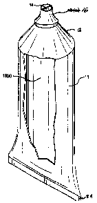
The present tubular container is shown in Figure 1. Tubular
container 10 has sidewall 1i and shoulder 1~. The shoulder terminates in
nozzle 16 which has an apertu:e having openings 20 and 2Z. Divider
1$ wall 1B separates chamber ZO from 22. The divider wall 1S extends
downwardly to the crimp seal 14. The crimp seal is shown as being offset
90° from the plane through the divider uTall at the nozzle exit of the
tubular
chamber.
Ti figure ~ shows the diW der wall l S/a) at a point about halfway
between the crimp seal 14 and the nozzle 1b. It is seen that the divider wall
at this point has an "S" shape and has a length that is approximately one
half the circumference of the tubular container. In this way the divider
wall 18 can be disposed within the crimp seal 14, This will produce a three
Dyer seal, This divider wall has a high degree of flexibility.
It is preferred that the divider wall 18 be substantially less in
thickness than the $idewall 11 and that it be more pliable. The divider wall
will have a thickness of about .05mm to about .l5mm and preer>wbly about
.07mm to about .l3mm. The ~idewall will have a thickness of about 0.2mm
to 0.8mm and preferably about 0.2mm to 0.6mm.
Figure 3 shows the divider wall in more detail in the full construction
of the tube. It is seen that the divider wall extends dawn through the tube
to the crimp seal 14. Fhrther, the exit divider wall is shown offset from the
-4-
AME('~nE~ SHEET
____..~..

v t c» : tr~,,~ 111 t-:\CHE\ r) l r.:,- , , -. _ . _
.. . . ,_, p. I .' . . ~ . * ,:, . ,'. . '. L~ U .~. . L . n l ~Y _
' . ~CA 02~2740~58~ 1999-06-03 -';. '- ~ _, .. .
crimp seal by about 90°C. There is a spiraling of the di«der wall 18
from
the crimp seal ug to and through the exit of divider wall 18. This spiral
nature to the divider wall, the general "S" shape of the divider -all, and the
xelatively thin structure of the divider wall, all contribute to a uniform
dispensing of products from each chamber of the tube. Uniform dispen$ing
is a necessary feature for dual chamber and other multichamber tube
containers. The cylindrical poriton of the tube terminates ir_ shoulde: 1~
and a nozzle if .
The sidewalls and the inner divider web wall can be comprised of a
single layer or multilayer laminate structure. The useful materials include
polypropylene, polyethylene (high to low density, polybutadiene, ethylene
vinyl alcohal, ethylene vinylacetate, vinylidene chloride, polyethylene
terephthalate, polybutylenc terephthalate, polyacrylonitile and laminate
structures that use layers of these materials. In many instances the
sidewall will be a laminate structure while the web wall will be a monolayer.
It is preferred that the divdcr web wall be as thin as possible which makes a
monolayer, and a thin multilayer, useful. However, the divider web wall can
be of a multilayer structure depending an the barrier and other properties
desired for this wall.
The present invention can be modified as to sidewall and divider web
wall materials and characteristics. However, any m.odificativns which
functionally produce the same tubular container arc wahin the present
invention.
V
-a-
ANic~!~E~ SHEET
~pFAIEP

Representative Drawing
A single figure which represents the drawing illustrating the invention.
Administrative Status

2024-08-01:As part of the Next Generation Patents (NGP) transition, the Canadian Patents Database (CPD) now contains a more detailed Event History, which replicates the Event Log of our new back-office solution.

Please note that "Inactive:" events refers to events no longer in use in our new back-office solution.

For a clearer understanding of the status of the application/patent presented on this page, the site Disclaimer , as well as the definitions for Patent , Event History , Maintenance Fee  and Payment History  should be consulted.

Event History

Description Date
Time Limit for Reversal Expired 2017-12-04
Letter Sent 2016-12-05
Grant by Issuance 2006-03-14
Inactive: Cover page published 2006-03-13
Inactive: Final fee received 2006-01-04
Pre-grant 2006-01-04
Notice of Allowance is Issued 2005-07-14
Letter Sent 2005-07-14
Notice of Allowance is Issued 2005-07-14
Inactive: Approved for allowance (AFA) 2005-06-09
Amendment Received - Voluntary Amendment 2005-06-02
Letter Sent 2002-12-13
Amendment Received - Voluntary Amendment 2002-12-11
Request for Examination Requirements Determined Compliant 2002-11-04
Request for Examination Received 2002-11-04
All Requirements for Examination Determined Compliant 2002-11-04
Letter Sent 1999-11-24
Inactive: Single transfer 1999-10-26
Inactive: Courtesy letter - Evidence 1999-09-17
Inactive: Cover page published 1999-08-27
Inactive: Single transfer 1999-08-20
Inactive: First IPC assigned 1999-08-06
Inactive: Courtesy letter - Evidence 1999-07-20
Inactive: Notice - National entry - No RFE 1999-07-14
Application Received - PCT 1999-07-12
Application Published (Open to Public Inspection) 1998-06-11

Abandonment History

There is no abandonment history.

Maintenance Fee

The last payment was received on 2005-09-15

Note : If the full payment has not been received on or before the date indicated, a further fee may be required which may be one of the following

  • the reinstatement fee;
  • the late payment fee; or
  • additional fee to reverse deemed expiry.

Patent fees are adjusted on the 1st of January every year. The amounts above are the current amounts if received by December 31 of the current year.
Please refer to the CIPO Patent Fees web page to see all current fee amounts.

Owners on Record

Note: Records showing the ownership history in alphabetical order.

Current Owners on Record
COLGATE-PALMOLIVE COMPANY
Past Owners on Record
JAMES C. MCKINNEY
PATRICK ANDRE CONNAN
ROBERT MACK
Past Owners that do not appear in the "Owners on Record" listing will appear in other documentation within the application.
Documents

To view selected files, please enter reCAPTCHA code :


To view images, click a link in the Document Description column (Temporarily unavailable). To download the documents, select one or more checkboxes in the first column and then click the "Download Selected in PDF format (Zip Archive)" or the "Download Selected as Single PDF" button.

List of published and non-published patent-specific documents on the CPD .

If you have any difficulty accessing content, you can call the Client Service Centre at 1-866-997-1936 or send them an e-mail at CIPO Client Service Centre.

({010=All Documents, 020=As Filed, 030=As Open to Public Inspection, 040=At Issuance, 050=Examination, 060=Incoming Correspondence, 070=Miscellaneous, 080=Outgoing Correspondence, 090=Payment})


Document
Description 
Date
(yyyy-mm-dd) 
Number of pages   Size of Image (KB) 
Representative drawing 1999-08-25 1 6
Abstract 1999-06-02 1 52
Description 1999-06-02 5 225
Claims 1999-06-02 2 44
Drawings 1999-06-02 1 25
Description 2005-06-01 6 241
Claims 2005-06-01 1 33
Representative drawing 2005-06-09 1 6
Notice of National Entry 1999-07-13 1 194
Reminder of maintenance fee due 1999-08-03 1 114
Courtesy - Certificate of registration (related document(s)) 1999-11-23 1 115
Reminder - Request for Examination 2002-08-05 1 128
Acknowledgement of Request for Examination 2002-12-12 1 174
Commissioner's Notice - Application Found Allowable 2005-07-13 1 160
Maintenance Fee Notice 2017-01-15 1 178
PCT 1999-06-02 15 492
Correspondence 1999-07-19 1 30
Correspondence 1999-09-16 1 13
Correspondence 2006-01-03 1 37