Note: Descriptions are shown in the official language in which they were submitted.
CA 02274336 1999-06-11
_a
L
EXPANDABLE BELT AND TREAD DRUM
FIELD OF INVENTION
This invention relates to equipment for use in the
manufacture of vehicle tires and particularly to a belt and
tread drum having novel diameter expansion/retraction
capabilities.
BACKGROUND OF INVENTION
Vehicle tire manufacture most commonly takes place in
stages. In an early stage of the manufacturing procedure,
there is formed a belt and tread package. This package
comprises a plurality of strips (belts) of elastomeric
material and/or other similar components that are formed into
a toriodal shape by winding the strips about the outer
circumference of a rotating belt and tread drum, with bonding
of the strips into the belt and tread package. Commonly, the
belt and tread package also has included therein metal bead
rings that ultimately aid in defining the rim diameter and
circumference of the tire. The package thus formed is
nonexpandable in diameter. After the package has been formed
on the belt and tread drum, the drum most commonly is
collapsed in outer circumference to allow removal of the
formed package from the drum. Thereafter, the drum is
expanded to its desired outer circumference for the forming of
a subsequent belt and tread package thereon. The belt and
tread package which has been removed from the drum is conveyed
1
CA 02274336 1999-06-11
to a further stage in the procedure where it is married to a
tire carcass and undergoes other stages of manufacture.
In the vehicle tire manufacturing industry, there are
many belt and tread machines which have been in use for
several years. These machines generally include a core which
is cantilevered on a rotatable shaft that is connected at one
of its ends to a drive mechanism. The core generally includes
some form of outer generally cylindrical shell whose diameter
(hence its circumference) is changeable within limits to
permit the shell to be collapsed in diameter for removal of a
formed belt and tread package therefrom. A substantial number
of these shells have no provisions for selecting different
overall diameters of the drum and therefore are limited to the
manufacture of a belt and tread package for a single size
tire. Some of these existing shells have some capacity for
changing the overall diameter of the drum, but are most
commonly very limited in their range of possible diameter
change. It is desired that these existing belt and tread
drums be retrofitted with means for enhancing the range of
diameters possible to be obtained with the drum, hence make
the drum useful in the manufacture of a greater range of tire
sizes. It is also desired that the changeover between
diameters be made more efficient and friendly to the equipment
operator. Attaining these desired results is greatly impeded
because of certain of the limitations imposed upon the
2
CA 02274336 1999-06-11
7 T -~~v
t
permissible modifications that can be accepted in designing a
retrofit shell for these drums. Specifically, commonly the
core of these existing machines is very large in diameter,
leaving relatively little annular space in which to make
modifications to the shell of the drum. Further, the machines
are designed to provide ancillary services, pressurized air
for example, to the shell which currently is employed with the
machine and any retrofitted shell preferably must be adapted
to the location and value of such ancillary services.
It is an object of the present invention to provide a
belt and tread drum which includes enhanced
expansion/retraction capabilities.
It is another object to provide a retrofit shell for an
exiting core of a belt and tread drum.
SUMMARY OF INVENTION
In accordance with one aspect of the present invention,
there is provided a belt and tread drum which includes an
improved annular shell that includes a plurality of
circumferentially spaced apart segments, each of which
includes an arcuate surface such that the collection of
segments defines an outer circumference of the drum. These
segments are radially moveable inwardly and outwardly relative
to the longitudinal centerline (also the rotational axis) of
the drum by means of a plurality of link pairs that connect
3
CA 02274336 1999-06-11
_.,
the segments to a carrier. The several carriers are disposed
at spaced apart locations about the circumference of an
actuator, which, in turn, is disposed in circumscribing non-
fixed relationship to a generally cylindrical hub which, in
turn, is disposed in circumscribing fixed relationship to a
core of the drum. Radial movement of the several carriers is
effected simultaneously by rotation of the actuator about the
hub and its supporting core, the rotational movement of the
actuator being converted into radial movement of the carriers
and their attached segments by the link pairs.
In accordance with one aspect of the present invention,
the tubular actuator is rotated about the hub, hence about the
core and rotational axis of the drum, by means of a piston
member that is pneumatically or hydraulically powered for
reciprocating movement within a chamber defined interiorly of
and between the actuator and the hub. In one embodiment, that
surface of the piston contiguous to the hub is provided with
a cam follower that rides in a helical groove provided in the
external surface of the hub. The piston is restrained against
rotation relative to the actuator during its reciprocatory
movement so that its longitudinal movement results in
rotational movement of the actuator.
Driving power for extension of the piston from its
retracted, at rest, position is provided by pneumatic or
hydraulic pressurized fluid. Spring means associated with the
distal end of the piston (opposite that end of the piston
which is exposed to the pressurized fluid) provide for
4
CA 02274336 1999-06-11
i r
retraction (return) of the piston from its extended position
to its retracted, at rest, position.
In accordance with a further aspect of the present
invention, the degree of radial movement of the segments of
the drum is selectable between maximum and minimum limits. In
the depicted embodiment, this movement selection is by means
of a hand wheel mounted exteriorly of the drum at one end
thereof. Rotation of this hand wheel, acting through a gear
member, that is drivingly connected to the actuator, the
degree of rotation of the actuator within the limits set by
the selection of the rotational position of the hand wheel.
Locking means, including an infinitely adjustable connector
ring disposed between the actuator and the gear member, is
provided for selectively effecting and releasing
interconnection between the gear member and the actuator. To
change the limits of rotation of the actuator, the locking
means is released. Once the hand wheel has been moved to the
desired location, the locking means is moved to a locking
position wherein the degree of rotation of the actuator is
fixed.
BRIEF DESCRIPTION OF THE FIGURES
Figure 1 is an end plan view of one embodiment of a
belt and tread drum embodying various of the features of the
present invention;
Figure 2 is a side plan view of the belt and tread drum
CA 02274336 1999-06-11
r ..,
depicted in Figure 1;
Figure 3 is a sectional view of the belt and tread drum
of Figure 1 taken generally along a diameter of the drum, but
modified with respect to the relational position of various
components of the drum in order to depict certain of these
components in a single, Figure;
Figure 4 is a further sectional view of the belt and
tread drum of Figure 1 taken generally along a diameter of the
drum, but further modified with respect to the relational
pcsition of various components of the drum in order to depict
certain of these components in a single Figure;
Figure 5 is an enlarged view of that portion of Figure 3
taken generally along the line C-C of Figure 3;
Figure 6 is a partial sectional view of the belt and
tread drum of Figure 1 and taken generally along the line A-A
of Figure 1;
Figure 7 is a partial sectional view of the belt and
tread drum of Figure 1 and taken generally along the line B-B
of Figure 1;
Figure 8 is an exploded representation of one embodiment
of a segment useful in the belt and tread drum of the present
invention;
6
CA 02274336 1999-06-11
t
T
Figure 9 is an exploded top plan view of the sections of
the segment of Figure 8;
Figure 10 is an end view of the sections depicted in
Figure 9;
Figure 11 is an end view of the sections depicted in
Figure 9 and with the sections pivotally joined and further
depicting the pivotal movement of the side sections with
respect to the central section of the segment;
Figure 12 is a side view of a connector plate employed in
the interconnection of adjacent segments of the present belt
and tread drum;
Figure 13 is a partial end view of two adjacent connector
plates and depicted their relative positions when adjacent
segments are expanded and retracted radially to select the
outer circumference of the drum;
Figure 14 is a side plan view of a carrier as employed in
the present invention;
Figure 15 is an end view of the left hand end of the
carrier depicted in Figure 14;
Figure 16 is a side view of one link as employed in the
present invention;
CA 02274336 1999-06-11
r
Figure 17 is a plan view of the link depicted in Figure
16;
Figure 18 is a side view of a further link as employed in
the present invention;
Figure 19 is a plan view of the further link depicted in
Figure 18;
Figure 20 is an end view of an actuator as employed in
the present invention;
Figure 21 is a sectional view of the actuator depicted in
Figure 20 and taken generally along the line 21-21 of Figure
20;
Figure 22 is an end view of a rear actuator support ring
as employed in the present invention;
Figure 23 is a sectional view of the actuator support
ring depicted in Figure 22 and taken generally along the line
23-23 of Figure 22;
Figure 24 is an end view of a hub as employed in the
present invention;
Figure 25 is a sectional view of the hub depicted in
Figure 24 and taken generally along the line 25-25 of Figure
24;
8
CA 02274336 1999-06-11 -
r
--.
Figure 26 is a side view of a portion of the outer
circumference of the hub depicted in Figure 26 and depicting a
helically oriented groove in the outer circumference of the
hub;
Figure 27 is an end view of a piston as employed in the
present invention;
Figure 28 is a sectional view of the piston depicted in
Figure 27 and taken generally along the line 28-28 of Figure
27;
Figure 29 is a side view of the piston depicted in Figure
27 and depicting a groove provided in the outer circumference
thereof;
Figure 30 is an end view of an adjustment stop gear as
employed in the present invention;
Figure 31 is a sectional view of the adjustment stop gear
depicted in Figure 30 and taken generally along the line 31-31
of Figure 30;
Figure 32 is a detailed sectional view of a portion of
the adjustment stop gear depicted in Figure 33;
Figure 33 is a schematic representation of a portion of
an adjustment ring gear, a translation gear and a post
associated with an actuator as employed in the present
9
CA 02274336 1999-06-11
.
invention;
Figure 34 is a plan view of a adjustment lock block as
employed in the present invention;
Figure 35 is a sectional view of the adjustment lock
block depicted in Figure 34 and taken generally along the line
35-35 of Figure 34;
Figure 36 is a sectional view of a translation gear as
employed in the present invention and taken generally along
the line 36-36 of Figure 37;
Figure 37 is a right hand end view of a translation gear
as viewed in Figure 36;
Figure 38 is a plan view of an adjustment hand wheel as
employed in the present invention;
Figure 39 is a sectional view of the adjustment hand
wheel depicted in Figure 38 and taken generally along the line
39-39 of Figure 38;
Figure 40 is an enlarged detail view of a portion of the
adjustment stop wheel depicted in Figure 38;
Figure 41 is a plan view of a scale ring as employed in
the present invention;
CA 02274336 1999-06-11
Figure 42 is a sectional view of the scale ring depicted
in Figure 41 and taken generally along the line 42-42 of
Figure 41;
Figure 43 is a plan view of a scale lock ring as employed
in the present invention; and
Figure 44 is a sectional view of the scale lock ring
depicted in Figure 43 and taken generally along the line 44-44
of Figure 43.
DETAILED DESCRIPTION OF INVENTION
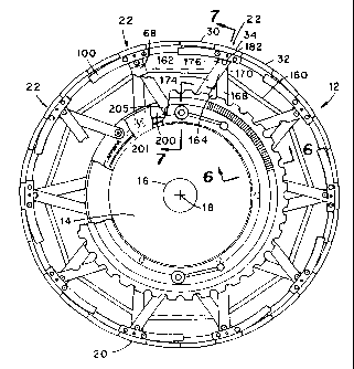
With reference to Figures 1 and 2, in the depicted
embodiment of the present invention, there is provided a belt
and tread drum indicated generally by the numeral 12 and
having opposite ends 13 and 15. The depicted drum includes a
cylindrical core 14 (shown only in phantom) which is adapted
to be mounted on a shaft 16 for rotation of the drum about its
longitudinal axis 18 (i.e. rotational axis) by a conventional
drive means (not shown). In the present invention, a
generally cylindrical shell 20 is provided in circumscribing
relationship to the core.
The depicted shell 20 includes a plurality of elongated
segments 22, each of which is made up of a plurality of
sections 30, 32 and 34. Each section includes an arcuate
surface 40, 42 and 44, respectively, that is oriented facing
radially outwardly of the drum. The plurality of arcuate
11
CA 02274336 1999-06-11
.,
surfaces of the segments collectively define the outer
circumferential surface of the drum.
More specifically, the shell 20 of the depicted belt and
tread drum 12 includes a plurality of circumference-defining,
multi-sectioned segments 22 whose outer surfaces collectively
define an arcuate segment of the outer circumference of the
drum 12. Each segment 22 is mounted to a carrier 150 for
radial movement with respect to the longitudinal centerline 18
of the drum 12.
As best shown in Figures 2 and 8, each segment 22 of the
depicted drum 12 includes a first side section 30, a second
side section 32 and an intermediate section 34 disposed
between the side sections 30 and 32. Each side section 30 or
32 of each segment 22 is provided with a plurality of slots 35
along one of its longitudinal side margins. Defined between
these slots 35 are alternating fingers 36 that are designed to
be received within the slots 35 of the side section 30 or 32
of an adjacent segment 22. In Figure 3, the several segments
22 are depicted with the fingers 36 of the side sections
thereof being substantially received within respective mating
slots 35 of adjacent segments 22. In this position of the
segments 22, the circumference of the drum 12 is at its
minimum value. In the maximum expanded circumference of the
drum, the fingers 36 of the several segments 22 being
withdrawn (partially) from the slots 35 of respective adjacent
segments 22.
12
CA 02274336 1999-06-11
_._
With reference to Figures 2,8-13, each of the side
sections 30 and 32, and the intermediate section 34 extends
along almost the entire length of the drum 12 and defines an
outer arcuate surface 40, 42 and 44, respectively. In
addition, each side section 30 and 32 includes a stepped
marginal edge opposite the fingers 36 having a lip 46. Along
the end surface of the outermost finger, indicated 36A, of
each side section 30 or 32, there is provided a bore 48 whose
purpose will become apparent herein, and there is provided in
opposite ends of the lip 46 bores 50 and 50A which are used
to hingedly attach the side section 30 and 32 to the
intermediate section 34 in a manner described herein.
With reference still to Figures 2,8-13, each intermediate
section 34 includes a stepped marginal surface extending along
the sides thereof and which includes a lip 52. As depicted,
there is provided along one side of the lip 52 (i.e. the upper
surface as shown in Figure 9) are pairs of internally-threaded
openings 54 and 54' used in the hinged attachment of the
intermediate section 34 to a corresponding one of the side
sections 30 and 32 in a manner described hereinafter. Defined
in the outer surface 44 of the intermediate section 34 and
adjacent the ends thereof are through-bores 56, 58 for
accepting bolts 60 and 62 (Figure 3) with which the segment 22
is attached to a corresponding carrier 68, (see also Figures 2
and 9 ? .
For hingedly securing one end of each side section
30 or 32 to their respective intermediate section 34 and with
13
CA 02274336 1999-06-11
r , .
reference again to Figure 8, there are provided stud members
70 and 70', each having a body 72 and a pin portion 74
projecting from the body 72. Each stud member, 70 for
example, is secured to the intermediate section 34 with screws
75 which extend through the body 72 of the member 70 and are
threadably received by the internally-threaded openings 54 and
54' (Figure 9) of the. intermediate member 34. Once the stud
members 70 and 70' are secured to the intermediate section 34
with the screws 75, each side section 30 or 32 is arranged
adjacent a corresponding marginal side edge of the
intermediate section 34 so that the lip 46 of the side section
30 or 32 overlies the lip 52 of the corresponding marginal
edge of the intermediate section 34 and so that the bores 50
and 50' provided in an end of each of side sections 30 or 32
pivotally accepts the pin portion 74 of a corresponding stud
member 70 and 70'.
With reference to Figures 1,2,8, 12 and 13, each segment
22 also includes guide means 98 and 98' mounted on the
opposite ends of a segment 22 for coordinating the movement of
the side sections 30 and 32 with those side sections of an
adjacent segment 22 as the segments 22 are moved radially of
the drum axis 18. The guide means 98 and 98' of the depicted
embodiment includes a pair of elongated plates 100 and 100'
each having two opposite ends 102, 102' and 104, 104' and two
opposite side faces 106, 106' and 108, 108' extending between
the ends 102, 102' and 104, 104' respectively. As best shown
in Figures 8 and 12, each guide plate 100, for example, is
arcuate in shape so that the curvature of its outer surface,
14
CA 02274336 1999-06-11
r r
indicated 110, corresponds with that of the outer surfaces 40,
42 and 44 of the segment sections 30, 32 and 34. Two through-
openings 112 and 114 extend between the faces 106 and 108 for
receiving the shanks of bolts 116, 118 (Figure 8) used to
attach the plate 100 to a corresponding end of the
intermediate section 34. As depicted the end 102 of the guide
plate 100 projects laterally (to the left as viewed in Figure
8) from the section 34. The guide plate 100' is mounted to
the opposite end of the section 34 in like manner but with the
end 102' thereof projecting from the section 34 to the right
as viewed in Figure 8.
Furthermore, a through-bore 120 extends between the faces
106, 108 at a location adjacent the plate end 104. One end of
a pin 122 (Figures 8,12) is fixed within the through-bore 120,
and the other end of the pin 122 is loosely received in a bore
121 provided in the side face of the outermost finger 36A of
the side section 32. It follows that with one end of each
side section 30 or 32 being secured to the intermediate
section 34 by way of a stud member 78, 78' and the other end
of each side section 30 or 32 being secured to the
intermediate section 34 by way of the guide plates 100, 100'
and pin 122, 122' each side section 30 or 32 is pivotally
attached to the intermediate section 34 for hinged movement
relative thereto about a pivot axis 124 or 126 between its
position shown in solid lines in Figure 11 and its position
shown in phantom in Figure 11. Accordingly, the diameter of
each bore 121 is slightly larger than the diameter of the
corresponding pin portion 74 or pin 122 accepted thereby.
CA 02274336 1999-06-11
r ,
When each segment 22 is secured to its carrier (Figure 1) in
its operative position about the drum 12, each axis 124 or 126
about which the side section 30 or 32 is permitted to pivot is
substantially parallel to the drum axis 18.
With reference again to Figures 8, 12 and 13, each guide
plate 100, 100' is also provided with an elongated slot 130,
130' which is defined within each guide plate so as to extend
substantially linearly along its side face 108. As best shown
in Figure 12, the end 132 of the slot 130 situated adjacent
the plate end 102 is closer to the outer surface 110 of the
plate 100 than is the opposite end 134 of the slot 130 thereby
orienting the slot at an angle with respect to a radius of the
apparatus. It is a feature of the guide plate 100 that as
each segment 22 is moved radially toward or away from the drum
axis 18, the side sections 30 and 32 of an adjacent segment 22
are pivotally moved relative to its corresponding intermediate
section 34 by a corresponding amount. To this end and with
reference again to Figure 8, one end of a pin 136, 136' is
fixedly received in the outermost finger 36A, 36A' of each
side section 30 and 32 adjacent the tip thereof, and the other
end of the pin 136, 136' is loosely received in the slot 130,
130' of a respective guide plate 100 of an adjacent segment
22. Thus, as the intermediate section 34 of each segment 22
is moved radially toward or away from the drum axis 18, the
pin 136 is guided along the slot 130. Alternately, the guide
plate may be provided with a curved outer surface which is
engaged by the pin of an adjacent side section in the nature
of a cam and cam follower.
16
CA 02274336 1999-06-11
L . ~1
It follows from the foregoing that as the segments 22 are
moved radially toward and away from the drum axis 18 between,
for example, the position illustrated in solid lines in Figure
13 and the position illustrated in phantom in Figure 13, the
guide plates 100 of adjacent segments 22 move closer together
or further apart. As the plates 100 are moved relative to one
another in this manner., each pin 136 (to which a side section
30 or 32 is secured) slidably moves along its corresponding
slot 130 from one end 132 of the slot 130 to the opposite end
134 of the slot 130. Furthermore, since the slot 130 is
oriented as aforedescribed (so that one of its ends is
situated closer to the outer surface 110 than is the other
end), the side sections 30 and 32 of the adjacent segment 22
are hingedly moved relative to its intermediate section 34
about the pivot axes 124 or 126 as the intermediate section 34
is moved toward and away from the drum axis 18. In other
words, as the intermediate section 34 of one segment 22 is
moved radially outwardly of the drum axis 18, the side
sections 30 and 32 of the one segment 22 are hingedly moved by
the guide plates 100 of an adjacent segment 22 relative to the
intermediate section 34 from, for example, the solid line
position shown in Figure 11 toward the position shown in
phantom in Figure 11. Conversely, as the intermediate section
34 of one segment 22 is moved radially toward the drum axis
18, the side sections 30 and 32 of the one segment 22 are
hingedly moved by the guide plates 100 of an adjacent segment
22 relative to the intermediate section 34 from, for example,
the Figure 11 phantom-line position toward the Figure 11
solid-line position.
17
CA 02274336 2006-03-17
Further description of the segments 22 is given
in US Patent 5,653,016 issued June 3, 1997 and
entitled: TRANSFER RING OR DRUM APPARATUS WITH
ADJUSTABLE CIRCUMFERENCE.
Whereas there is described herein a "three-sectioned"
segment, it is to be recognized that in accordance with one
aspect of the present invention, each segment may comprise
only two sections which are hingedly connected as by a
hinge rod about a common hinge line.
As noted, each of the shell segments 22 is mounted to
a respective one of plurality of carrier members 68. With
reference to Figures 1-6, 14 and 15, each carrier
member 68, in the depicted embodiment, comprises an
elongated body portion 150 that extends substantially
between the opposite ends 13 and 15 of the drum. Each
carrier member further includes, adjacent one of its ends,
end 152, for example, a radially inwardly projecting lug
154. Each lug 154 is provided with first and second
through passageways 156 and 158 for receiving therein
stabilizing rods 160 and 162 (see Figure 2) as will be
further described hereinafter.
Each carrier member 68 serves also as the mounting for
first and second pairs of links, indicated generally by the
numerals 164 and 164'respectively. As depicted in Figures
1, 3-6, 16-19, the first pair of links 164 includes a first
elongated link 168 having opposite ends 170 and 172, and a
18
CA 02274336 1999-06-11
-.
second elongated link 174 having opposite ends 176 and 178.
The end 170 of the first link 168 and the end 176 of the
second link 174 is pivotally pinned to the end 180 of the
carrier member 68, for example, by a common pin 182 having one
end 184 thereof anchored in a bore 186 in the end 180 of the
carrier 150 as by a set screw 188. From the common pin 182,
the links 168 and 174 .extend generally radially inwardly of
the drum. These links 168 and 174 are individually pivotable
about their common pinning axis 190. Screw means 192 is
provided in the outboard end of the pin 182 to retain the link
174 on the pin.
The second set of links 166 includes a first elongated
link 168' having opposite ends 170' and 172', and a second
elongated link 174' having opposite ends 176' and 178'. The
end 170' of the first link 168' and the end 176' of the second
link 174' are pivotally pinned to the end 181 of the carrier
member 68 by a common pin 183 having one end 185 thereof
anchored in a bore 187 in the end 181 of the carrier 68 as by
a set screw 189. From the common pin 183, the links 168' and
174' extend generally radially inwardly of the drum. These
links 168' and 174' are individually pivotable about their
common pinning axis 192. Screw means 193 is provided in the
outboard end of the pin 183 to retain the link 174' on the
pin. As depicted, the pinning axes of the pins 182, 183, 201,
203, 205, 207 are parallel with one another and with the
rotational axis 18 of the drum. By this means, rotation of
the actuator 200 about the longitudinal centerline 18 of the
drum results in only arcuate displacement of the pins 205,
19
CA 02274336 1999-06-11
.
207, hence arcuate displacement of the ends 172, 172' of the
links 174, 174'. Notably, this arcuate displacement of the
pins, hence the ends of the links, does not alter their radial
distance from the longitudinal centerline of the drum.
The radially inward ends of the several links 168, 168',
174 and 174' are pivotally mounted to the hub 220 or to the
actuator 200. Specifically, the radially inward ends 178,
178' of the links 174, 174' are pivotally mounted on the hub
as by pins 201, 203, hence their respective pivot axes are
fixed. The radially inward ends 172, 172' of the other links
168, 168' of the sets of links are pivotally mounted on the
actuator 200 as by pins 205, 207. The actuator is rotatable
relative to the hub so that the pivotal axes of the ends 172,
172' of the links 168, 168' are displaceable along a circular
path that is concentric with the rotational axis 18 of the
drum and with the hub. Thus, it will be recognized that
circumferential displacement of the pivotal axes of the
radially inward ends of the first links, 168, 168' relative to
the pivotal axes of the radially inward ends 178, 178' of the
second links 174, 174' serves to move these pivotal axes
together or apart, depending upon the direction of rotation bf
the actuator relative to the hub.
The several carrier members 68 and their associated
segments 22 are disposed at spaced apart locations about the
circumference of the generally tubular actuator 200. As best
seen in Figures 3-7, 21 and 22, the actuator 200 includes a
"U" shaped circumferential groove 202 adjacent one end 204 of
CA 02274336 1999-06-11
the actuator and which opens radially outwardly. This groove
202 is of a geometry and size suitable for the slidable
receipt therein of the lugs 154 of the several carrier members
68. Thus, the actuator is free to rotate relative to the
fixed-position carrier members and. about the longitudinal axis
18 of the drum.
Adjacent the opposite end 206 of the actuator 200 there
is provided a support ring 208 adapted to be removable secured
to the end 206 of the actuator as by screws 210 (Figure 3).
When in place on the actuator, the ring 208 projects radially
inwardly of the actuator and defines a circumferential
shoulder 212 that is adapted to slidably engage the outer
surface 230 of the hub.
The actuator 200 is mounted in encircling relationship
with the generally tubular hub 220. The hub 220 is fixedly
secured in encircling relationship with the cylindrical core
14. The actuator is rotatable about the fixed hub. Circular
seals 222, 224 and 226 disposed between the inner
circumferential surfaces 228 and 212 of the actuator and the
outer circumference 230 of the hub are provided to preclude'
to flow of gas or liquid past the location of the seals for
purposes which will appear herein.
Since the hub 220 is fixed against rotation with respect
to the core 14, and the ends of the links 174, 174 of the
pairs of links remain stationary and do not move when there is
arcuate displacement of the pinning axes of these ends, any
21
CA 02274336 1999-06-11
arcuate movement of these pinning axes which is the result of
rotation of the actuator relative to the hub causes the
pinning axes of these pins to move arcuately apart or toward
their common longitudinal alignment. It will be recognized
that this arcuate displacement of these pinning axes
associated with the ends 172, 172' of the links 168, 168' has
the effect of radially displacing the common pinning axis of
the commonly pinned ends 170, 170' and 176, 176' of the pairs
of links 164 and 166, hence concomitant radial displacement of
the carrier 68 and increase or decrease in the outer diameter
(circumference) of the drum.
In the present invention, the circumference of the drum
is effected at the commencement of a process for making a belt
and tread package of a desired size (for a given size tire).
This requires that the segments of the drum be moved radially
outwardly of the drum to expand the circumference of the drum
to the desired value. After the belt and tread package has
been formed on the expanded drum, the circumference of the
drum is reduced by retracting the segments radially inwardly
of the drum. This cycle of expansion/retraction commonly must
take place within about a 45 second time period. During a
given manufacturing time period, such as a work shift, it is
at times desired to change the size (diameter) of the belt and
tread package being produced so as to provide a belt and tread
package that is suitable for the manufacture of a different
size tire. To effect this cycle of expansion/retraction of
the segments of the drum, the present inventor provides for
radial expansion/retraction of the segments through the
22
CA 02274336 1999-06-11
rotational movement of the actuator between maximum and
minimum limits. With particular reference to Figures 3,4,and
27-29, there is depicted means for effecting rotational
movement of the actuator relative to the hub. In the depicted
embodiment, this means is in the form of a cylindrical piston
member 250 which is reciprocatably disposed within a
cylindrical cavity 252 defined between a portion of the
radially inward surface 254 of a wall 256 of the actuator and
a portion of the radially outward surface 258 of wall 260 of
the hub. Within the cavity, the piston is slidable between a
retracted position (to the left as viewed in Figure 3 and an
extended position (to the right as viewed in Figure 3) A
circumferential seal 262 is provided adjacent one end of the
piston to seal against the flow of pneumatic or hydraulic
fluid between the outer circumference of the piston and the
inner circumference of the cavity.
Power for propulsion of the piston from its retracted
position toward its extended position is provided from an
external source (not shown) of pressurized fluid which is
connected in fluid flow communication with a port 270 provided
through the wall 260 of the hub and into an internal
passageway 272 that leads from the port to the cavity at a
location adjacent the rear end 274 of the piston 250.
Pressurized fluid admitted to the cavity 2S2 through the port
270 and passageway 272 moves the piston from the left to the
right of the cavity as viewed in Figure 4. Return of the
piston to its retracted position is effected in the depicted
embodiment by one or more spring means 276 that is disposed
23
CA 02274336 1999-06-11
a.
within the cavity 254 and between the piston and the rear
support ring 208 for the actuator. As seen in Figures 4,27-
29, the spring means 276 may take the form of a plurality of
helically coiled springs 271 that encircle respective rigid
rods 273. One end 281 of each rod is anchored in the rear
support ring 208 and projects therefrom to provide support for
its encircling spring.. The opposite end 275 of each rod is
slidably received in a respective bore 277 in the piston.
Further, one end 283 of the spring 271 abuts the rear support
ring and the opposite end 285 of the spring is received within
a respective bore 277 in the piston, along with its respective
rod, and abuts the rear end 287 of the bore 277. When the
piston in is its retracted position (to the left as viewed in
Figure 4), only a small portion of the length of the rod is
disposed within its respective bore and the spring is
relatively relaxed. As the piston is moved toward its
extended position, more of the rod enters its bore and the
spring becomes compressed. The depth of the bore 277 is
chosen to provide for sufficient left-hand movement of the end
275 of the rod further into the bore by a distance which
permits the piston to move to the right, as viewed in Figure
4, by its selected maximum travel limit. It will be
recognized that this travel limit permits that amount of
piston movement which effects the desired degree of rotation
of the actuator.
As depicted in Figures 4,28 and 29, there is provided an
radially outwardly opening elongated groove 280 in the outer
circumference of the piston. This depicted groove is aligned
24
CA 02274336 1999-06-11
with its longitudinal axis parallel to the longitudinal axis
18 of the drum. A follower roller pin 282 is provided in the
wall 256 of the actuator and projects therefrom to be received
within the groove 280. Thus, the circular piston is precluded
from rotating relative to the actuator as the piston is moved
between its retracted and extended positions. The piston,
however, remains free to rotate with the actuator. Further,
there is provided a radially outwardly opening helically
oriented elongated groove 282 within the wall 260 of the hub,
this groove having opposite ends 283 and 285. A follower
roller pin 284 is provided in the wall 286 of the piston and
projects therefrom to be received within the helically
oriented groove 282. As the piston is moved between its
retracted and extended positions, the net effect is that the
piston and the actuator are rotated about the longitudinal
axis of the drum by an amount which is determined by the pitch
of the helical groove 282 and the distance of travel of the
piston. It will be recognized that the direction of the
rotation of the piston and actuator combination is reversed,
depending upon the direction of movement of the piston. Thus,
rotation of the actuator in a first direction functions to
expand the segments radially outwardly, and rotation of the
actuator in a second and opposite direction functions to
retract the segments radially inwardly of the drum. The
maximum and minimum limits of expansion and retraction of the
segments, under these conditions, is a function of the
distance of travel of the piston, hence the distance of travel
of the follower roller pin 284 along the length of the helical
groove 282. Since it is desired that the drum be capable of
CA 02274336 1999-06-11
producing several different size belt and tread packages for
different size tires, it is necessary that the length of the
helical groove, hence the permissible limits of travel of the
piston, be sufficient to permit piston movement (and
concomitant rotation of the actuator) over a distance which
encompasses all desired sizes of belt and tread packages.
Control over the distance which the pressurized fluid-powered
piston travels during a cycle is very difficult and imprecise.
Further, it is practically impossible to adjust the limits of
piston travel when it is desired that the maximum and minimum
limits of its travel be changed. In the present invention,
these problems are overcome by means of apparatus designed to
physically establish maximum and minimum limits of rotation of
the actuator about the hub, all within the greater maximum and
minimum limits of piston travel.
It is to be recalled that the hub is fixed against
rotation thereof relative to the longitudinal (rotational)
axis of the drum. As depicted in Figures 5-7 and 30-33, the
present inventor provides a locking ring gear 290 in
encircling relationship to the hub at a location adjacent the
circumferential inboard face 291 of the hub. This ring gear
190 includes an outboard face 292 which faces and slidably
engages the outboard face 291 of the hub. As will be noted
these faces may be moved into frictional engagement such that
the locking gear is prevented from rotating relative to the
hub. The outer circumference of the locking ring gear 290 is
provided with gear teeth 294. As seen in Figure 30, the
inboard surface 296 of the locking ring gear is further
26
CA 02274336 1999-06-11
.
provided with an outwardly opening elongated arcuate notch
298. As seen in Figures 6, 21 and 33, the outboard end 300 of
the actuator is provided with a post 302 which projects from
the end of the actuator and is received in the elongated notch
298 in the locking ring gear. Thus, when the locking gear
ring is fixed relative to the hub, the post 302 can only move
within the limits of the length of the notch 298. More
specifically, since the post 302 can not move past an end,
(end 304, for example) of the notch, the inventor further
provides for adjustment of the angular position of such end
304 of the notch 298 so that the rotation of the actuator is
halted at a selected angular position of the actuator. In the
present embodiment, the movement of the piston to its most
retracted position within the cavity 254 provides a well-
defined first limit of travel of the piston, hence a well-
defined limit of rotation of the actuator. This first limit
of rotation of the actuator establishes the minimum retraction
limit of the segments. That end 304 of the notch 298 which is
employed as a "stop" limit for the rotation'of the actuator
therefore functions as the selectable maximum limit of
expansion of the segments, hence the desired diameter of the
drum for the manufacture of a given size belt and tread
package ( t i re ) .
To selectively alter the angular position of the end 304
of the notch 298, relative to the post 302 on the actuator,
the present inventor includes means for selective interlocking
of the locking ring gear 290 with the stationary hub. In the
depicted embodiment, this means includes the inboard face 291
27
CA 02274336 1999-06-11
' ~ .
provided on the end 293 of the hub, this face 291 extending
circumferentially around the end of the hub. As discussed
hereinabove, the locking ring gear includes an outboard face
292 that extends circumferentially about the ring gear. At
least one locking lug 306, depicted separately in Figures 34
and 35, is provided at a location about the circumference of
the locking ring gear.and in position to selective urge the
locking ring gear laterally toward or away from the hub, hence
to cause engagement or disengagement of the faces 291 and 292.
This locking lug 306 includes an arcuate shoulder portion 310
that is adapted to be slidably received in an outwardly
opening circumferential groove 312 provided in the outer
circumference of the locking ring gear, inboard of the teeth
294 of the gear. By this means, the locking ring gear, when
unlocked, can be rotated relative to the hub. As depicted,
the locking lug 306 is threadably received on the inboard end
314 of a shaft 316 which is rotatably mounted in, and projects
through, a flange portion 318 on the end 293 of the hub to
extend outwardly from the locking lug 306 to the exterior of
the shell 20. The outboard end 320 of the shaft 316 is
provided with a locking handle 322 whose rotation functions
to move the locking lug laterally, hence between its locked
and unlocked positions with respect to the locking ring gear.
Rotation of the locking ring gear 290, when it is
unlocked from the hub, is provided for by means of a circular
hand wheel 330 that is rotatably mounted on the end 15 of the
drum by means of a plurality of translation gears 332 disposed
in angularly spaced apart locations on the end of the drum.
28
CA 02274336 1999-06-11
Each translation gear is mounted in, and extends through, the
flange 318 on the end 293 of the hub. Each translation gear
is provided on its inboard end 334 with a first set of gear
teeth 336. These gear teeth 336 are so disposed with respect
to the locking ring gear that the teeth 294 on the outer
circumference of the locking ring gear mesh with this first
set of gear teeth 336.. Each translation gear is further
provided with a second set of gear teeth 338 on its outboard
end 340. The hand wheel 330 is provided with a set of gear
teeth 342 on the inner circumference thereof, which latter
gear teeth mesh with the gear teeth 338 on the outboard end of
each of the translation gears. By this means, rotation of the
hand wheel can effect counter rotation of the locking ring
gear when the latter is disengaged from the hub. At such time
as the hand wheel is in its desired angular position, rotation
of the locking handle 322 associated with each translation
gear serves to lock the locking ring gear to the hub and
prevent any rotational movement of the locking ring gear until
such time as it is again released from the hub.
The outboard face 344 of the hand wheel is provided with
an alignment indicator 346. A scale ring 348 is mounted
outboard of the hand wheel 330 as by means of a retention ring
350 that overlies a portion of the inner margin 352 of the
scale ring and is fixed to the end 293 of the hub as by screws
354. The scale ring is provided with indicia 356 on its
outboard face 358 and about a portion of its circumference,
such indicia being disposed in cooperating relationship to the
alignment indicator on the hand wheel. This indicia is
29
CA 02274336 1999-06-11
:o
calibrated to visually indicate units of measure of the
diameter of the drum. Thus, alignment of the alignment
indicator on the hand wheel to a given drum diameter
indication on the scale functions to rotate the several
translation gears, hence rotate the locking ring gear, hence
select the angular position of the end 304 of the notch 298 in
the ring gear, hence select the limit of rotation of the
actuator in a direction which causes radial expansion of the
segments, so that upon the actuation of the piston in the
cavity to move the piston away from its retracted position
toward its extended position, the actuator is rotated only
until the post 302 on the actuator engages the end 304 of the
notch. Thereupon the rotation of the actuator is halted,
hence the movement of the piston 250 is halted. To maintain
the segments expanded to their selected maximum positions,
pressurized fluid is maintained in the cavity 252 to hold the
piston against movement thereof toward its retracted position,
under the influence of the spring means 276, until such time
as the belt and tread package has been formed and is ready to
be removed from the drum. Thereupon, the pressurized fluid is
released from the cavity and the piston returns to its
retracted position within the cavity under the influence o f
the spring means. Notably, the arcuate length of the notch
298 is selected such that the post 302 never engages the end
305 of the notch so that the length of the notch is not a
factor in determining the movement of the piston toward its
fully retracted position. On the other hand, the length of
the helical groove 282 in the outer circumference of the hub
is selected such that its opposite ends 283 and 285 establish
CA 02274336 1999-06-11
the maximum and minimum limits of travel of the piston within
the cavity 252. By these means, the maximum and minimum
diameters attainable for the drum are mechanically fixed and
are primarily a function of the available space within which
the several pairs of links can be fitted, which space
determines the permissible length of the links and the
permissible arcuate spacing of their radially inward ends.
The foregoing detailed description of the drum 12 is for
the purpose of illustration and not limitation. It should be
recognized that~a belt and tread drum embodying features of
the present invention could be made with numerous
modifications, substitutions, deletions and additions without
departing from the scope of the claims as set forth
hereinafter.
31