Language selection

Search

Patent 2274370 Summary

Third-party information liability

Some of the information on this Web page has been provided by external sources. The Government of Canada is not responsible for the accuracy, reliability or currency of the information supplied by external sources. Users wishing to rely upon this information should consult directly with the source of the information. Content provided by external sources is not subject to official languages, privacy and accessibility requirements.

Claims and Abstract availability

Any discrepancies in the text and image of the Claims and Abstract are due to differing posting times. Text of the Claims and Abstract are posted:

  • At the time the application is open to public inspection;
  • At the time of issue of the patent (grant).
(12) Patent Application: (11) CA 2274370
(54) English Title: CHARGING STATIONS FOR ELECTRIC VEHICLES
(54) French Title: POSTES DE RECHARGE POUR VEHICULES ELECTRIQUES
Status: Deemed Abandoned and Beyond the Period of Reinstatement - Pending Response to Notice of Disregarded Communication
Bibliographic Data
Abstracts

English Abstract


The main reason of the lack of success of EV projects was the
unability of the vehicle to get back in motion before those
long hours of recharging after their batteries have drained
out. This invention of mine is a modest try to encourage the
auto makers to make a move towards building pollution free
vehicles and gradually retire the internal combustion engine
ones.


Claims

Note: Claims are shown in the official language in which they were submitted.

CLAIMS:
The embodiments of the invention in which an exclusive
property or privilege is claimed are defined as follows:
1) A pillar-like connector that optionally and automatically
adjusts its height and depth that serves as an electricity
dispenser for charging batteries of EVs. (electric vehicles),
as well as parking meters for internal combustion motor
vehicles. This device can also be spaced in rows to serve
many vehicles at the same time in case of modular convoy
system and could also be built in walls or any other surface.
2) A manned, semi or fully automated station for charging
battery containers or "power packs" where the vehicles will
park at a loading bay. in case of front gate automobiles, an
equipment will come from out of the ground grasping the front
panel and move it away and out of the way, then a conveyor
shaft will approach penetrating and grasping the "pack's"

Page 4
front handles, after the device is secured and locked inside
the female holder of the vehicle and the rails aligned, will
take the "pack" to the next stage.
3) A device that serves to transport the front panels of
EVs. out of the way of the power packs to be interchanged to
freshly charged ones and puts it back when session is
finished.
4) A device that after docking firmly at the EV's chassis
will grasp the handles of the "pack" and delivers it to the
shafts of the conveyor car.
5) A conveyor car on two optional transverse rail systems
plus elevator mechanism that can transport power packs to a
and from the loading docks, to and from the charging
compartments, up and down and in any necessary direction in
both sides of the station.
6) The charging compartments will also have their mechanisms
of holding the "packs" and electric connectors similar to
the ones of the inner are of the vehicles they came from,
and they could be built in many rows and levels to save
space and time of operation. It is understood that the
handles of pacts as well as the locksmith type plates to
engage thereto could optionally be replaced by magnetic or
electromagnetic pads, the same applying to the holding
gadgets of all conveying shafts, onboard and inside charging
compartments.
7) A rack of probe tubes could be installed at the ceiling
of one, some or all the charging compartments that will come
down, penetrates the battery caps and will stop just above
the plates of each battery cell, will collect its solution,
checking the level and dispensing distilled water or other
necessary fluids as needed, and will check its working
conditions with its sensor and reporting to whoever
monitoring the data.
8) A tag placed in some area of the power pack easily to be
scanned that collects information about any possible
malfunction, age of the batteries, working status, etc.

Description

Note: Descriptions are shown in the official language in which they were submitted.


CA 02274370 1999-OS-31
SPECIFICATIONS:
A pillar-like electricity dispenser that electronically or
coin operated controls the billing and other functions of the
device. It can also replace the existing parking meters as it
can also take care of this kind of metering and subsequent
billing.
A manned, semi or fully automated stations for charging
"power packs" where the vehicles will park at a loading bay,
a conveyor shaft will approach taking along a supporting
plate that has the rail attached that will guide the power
pack out from the inside the body of the vehicle to the
inside the compartment of the charging station, and vice
versa. In case of automobiles a device will come up from the
ground and grasp the front panel that also serve as entering
steps, and move~'~out and ups out of the way of the moving power
pack, and returns to its original position right after the
freshly charged one are secured in place. This device doesn't
function in case of other vehicles or trailers. The station
will have also a mechanical device to take the pack out of
the vehicle and deliver to the conveyor car that circulates

CA 02274370 1999-OS-31
Page 2 of 9
back and forth, up an down and collects and delivers packs to
their compartments placed in many levels to save time of
operation. Some or all the compartments could have a rack
full of probe tubes that penetrates and service the batteries
whenever in need distilled water, etc, as well as make the
readings of their working status, reporting to a tag that
could be scanned and monitored at any time.
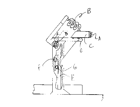
Fig.l Is the pillar type electricity dispenser that, as the
vehicle parks right besides, will move part (C) outwards
penetrating the electric contacts (A) in the vehicle's take
up contacts and dispense electricity as soon as the driver
makes the proper commands in the other side's panel. This
energy will travel from inner cables and through the flexible
cables (B). Motor (D) drives wheels (E) that will drive the
chain that will move the part (C) in and out. Motor (F) will
drive the shaft (Fl) up and down in order to align the
"nozzle" with the vehicle's take-up contacts. An inside
sensor controls the height of the "nozzle" and one onboard
controls the position of the vehicle and the charger making
the "fine-tune" driving.
Fig.2 is the device that will take the front panel of the
automobiles out of the way of the power packs and bring it
back right after the freshly charged one is back. (A) is a
tray that would come up from the underground making the
sticks (D) penetrate the holes of the panel to make it firm
to travel. Then the wheels (E) will roll away from the
vehicle at the same time triggering the elevator (B)
counteracting by the weights (C) moving together until find a
proper place atop the next machine.
Fig.3 Is a conveyor that acted by chain system illustrated in
(E) will make the shaft (C) move outwards making the plate
(A) penetrate the female holders of the vehicle and activate
the locking pin that penetrates the hole (B) and making the
plates (D) to engage the power pack holders to the (C) shaft.
After this is done, the system of the wheels (E) will work
the oposite way bringing the power pack out of the vehicle
and move towards the charging station. After certain point
the conveyor shaft will come to the end of the rope and the
"pack" is still far away from the next stage. Then the
conveyor shaft system will move upwards to the position (F)
and the wheels (Fl), forced upwards by the springs (I) will
come into action delivering the "pack" to the shaft of the
conveyor car that will take care of the rest of the trip.
Fig.4 is an inside view of the charging station showing at
the center the conveyor car that acted by the system (C) will
penetrate the shaft (A) into the holders of the "pack", will
release the plates (B) and will drag it from the previous
stage its center, then will move forwards or backwards,
straight or upwards to deliver the load to the charging
compartments (Fl). This same, or other similar cars, if
available, will make other pick-ups and deliveries in both

CA 02274370 1999-OS-31
Page 3 of 9
sides. Systems driven by wheels (I) and counter weighed by the
pads (K) will make the rails (M) go up and down, thus
elevating the power packs to desired level. Wheels (F)
rolling on rails (G) will provide back and forth movement for
the conveyor car, In case additional operation requires it to
move sideways, locks (L) should be released and wheels (E)
will make the car to move right or left. All these operations
could be manned, semi or fully automated.
Fig. 5 is a probe tube that coming down from the ceiling area
of the charging compartments, penetrates each battery cell
stopping just above their plates. The battery solution will
enter the vents (A) and sensor (E) will do the readings of
the level of solution and conditions of the cell,
transmitting the information to a tag located in some area of
the "pack" easy to be scanned. Should the solution is low,
the same tube will dispense necessary deistilled water or any
other chemicals to the battery cell. The wire (D) is what
connects the sensor (E) to the other side of the equipment.
Fig. 6 is the rack that will drive the above mentioned tubes,
all at the same time (B) one for each cell, that in order to
ensure perforation of all the battery caps at the same time,
would have some heavy beams at the frame (A). (D) would be
the cables or rods that will drive the whole rack up and
down, and (C) are the tubes and wires that will make the
possible the electronic readings as well as necessary fluid
dispensing.
Fig. 7 is a bird's eye view of a charging station where the
vehicles (E) will park, activate the pads (F) with a credit
card, punching a code, etc., will make the loading bay (A)
function and start the interchange session. (D) are the
charge compartments and (B) the conveyor cars that will roll
on rails (C).

Representative Drawing
A single figure which represents the drawing illustrating the invention.
Administrative Status

2024-08-01:As part of the Next Generation Patents (NGP) transition, the Canadian Patents Database (CPD) now contains a more detailed Event History, which replicates the Event Log of our new back-office solution.

Please note that "Inactive:" events refers to events no longer in use in our new back-office solution.

For a clearer understanding of the status of the application/patent presented on this page, the site Disclaimer , as well as the definitions for Patent , Event History , Maintenance Fee  and Payment History  should be consulted.

Event History

Description Date
Inactive: IPC deactivated 2021-10-09
Inactive: IPC deactivated 2020-02-15
Inactive: First IPC assigned 2019-02-15
Inactive: IPC assigned 2019-02-15
Inactive: IPC expired 2019-01-01
Time Limit for Reversal Expired 2003-06-02
Application Not Reinstated by Deadline 2003-06-02
Inactive: Adhoc Request Documented 2003-03-04
Deemed Abandoned - Failure to Respond to Maintenance Fee Notice 2002-05-31
Application Published (Open to Public Inspection) 2000-11-30
Inactive: Cover page published 2000-11-29
Inactive: Office letter 2000-10-02
Change of Address Requirements Determined Compliant 2000-07-14
Inactive: Office letter 2000-07-14
Inactive: First IPC assigned 1999-07-30
Inactive: IPC assigned 1999-07-30
Inactive: Office letter 1999-07-27
Inactive: Filing certificate - No RFE (English) 1999-07-26
Application Received - Regular National 1999-07-15

Abandonment History

Abandonment Date Reason Reinstatement Date
2002-05-31

Maintenance Fee

The last payment was received on 2001-05-30

Note : If the full payment has not been received on or before the date indicated, a further fee may be required which may be one of the following

  • the reinstatement fee;
  • the late payment fee; or
  • additional fee to reverse deemed expiry.

Patent fees are adjusted on the 1st of January every year. The amounts above are the current amounts if received by December 31 of the current year.
Please refer to the CIPO Patent Fees web page to see all current fee amounts.

Fee History

Fee Type Anniversary Year Due Date Paid Date
Application fee - small 1999-05-31
MF (application, 2nd anniv.) - small 02 2001-05-31 2001-05-30
Owners on Record

Note: Records showing the ownership history in alphabetical order.

Current Owners on Record
GLAUCIO ROBERTO DE PASCHOAL
Past Owners on Record
None
Past Owners that do not appear in the "Owners on Record" listing will appear in other documentation within the application.
Documents

To view selected files, please enter reCAPTCHA code :


To view images, click a link in the Document Description column. To download the documents, select one or more checkboxes in the first column and then click the "Download Selected in PDF format (Zip Archive)" or the "Download Selected as Single PDF" button.

List of published and non-published patent-specific documents on the CPD .

If you have any difficulty accessing content, you can call the Client Service Centre at 1-866-997-1936 or send them an e-mail at CIPO Client Service Centre.


Document
Description 
Date
(yyyy-mm-dd) 
Number of pages   Size of Image (KB) 
Representative drawing 2000-11-20 1 7
Claims 1999-05-30 2 75
Description 1999-05-30 3 141
Drawings 1999-05-30 5 88
Abstract 1999-05-30 1 11
Abstract 1999-09-26 1 11
Claims 1999-09-26 2 75
Filing Certificate (English) 1999-07-25 1 174
Notice: Maintenance Fee Reminder 2001-02-28 1 120
Notice: Maintenance Fee Reminder 2002-03-03 1 121
Courtesy - Abandonment Letter (Maintenance Fee) 2002-07-01 1 183
Second Notice: Maintenance Fee Reminder 2002-12-02 1 114
Notice: Maintenance Fee Reminder 2003-03-02 1 122
Correspondence 1999-07-26 1 20
Correspondence 2000-07-10 1 36
Correspondence 2000-07-13 1 7
Correspondence 2000-10-01 1 11
Correspondence 2003-07-15 1 32
Fees 2001-05-29 1 31