Note: Descriptions are shown in the official language in which they were submitted.
CA 02274409 2003-07-29
Ir~~:~:~. 53~U:~vv: ~:'~~'t>~~~~~i.ifi:~
~vl~~. ~:~~~f~:~~~~~~,w~v.~:~:~~: '~:'~~~f~':v 1~
~;~~~.~l.:~i:~~a~.~~.iv.~~~~rs ,~~,:~i~.~~ s:.c;~~v~.>'~rl~~ ~~
~'#~~~.~~*~'~~ Cs3-~t'~~l~A3~.'~ ~~.~xt.~ :?:3 lF~a~d~'~~s~ .~.C~
3~,'~?i~.'i"t i'..~>'~'~:~'~ i ~l~' -~t:.~3'~~~'1 i';'~ E~:~~.'
'~F3~i~~t?~'~..~;~
<>~ ".f., :: sy :w.y' S g'~.:;~~.' ' 's;..: '.,c. ;?" ,~;n-~ y_:~ .,~
~.~E.~;.ia,A~~,,~; ~:~:.f;~~. >:~:s ~;..~v~~~~~~. ~:~t~:z~.:~, t.~.~r~~e~
t.f.....,~' ~:r ~~...~.~::~.. .~~.:.:~..y;:.:-~~,..~,~, ~..~.. ~.~1.<~.~~. .i
. y<a, ~ ~~. 9;-'f..if ~s., _ . ~fw~vy; :<~ T'f ~ ~'sv ''f'.:
' 4:. 'n G ':~-iYY ~ _ ~ ~ , 'Y'- :~'~, f! . ,
~f'~.'ii:.~'3"~..~'1:~'t;~F.~~~i3;,'3 1'h:~if~.~~.,> .,f%
'tt~:,'~s'.~.~~..:~i~;;:t>.S?F~~~''t"Et.'-'~" :~.~zili;tis' L:fo"..~1.,~, >.i
yC",.~L.~~ c~.~v:'t~I 32?'s:3,~.s:.'Ci<.i
ya~.x3 ,3~ ~~~~~Wte .~w.A ~n ~~r w;aAs. ~~w~ ~~~~s~a~~~. ~ ~;3~.~~.~,1=~-
z~~~l~~x~.~ ~~~-~~~:~~~a~:~ ~t~~~t~~ w~
1~~>>~.'f~s;;'t'~:'s~;A ':5.yt ~' ~ f'~.'.~~;f. f.'~SF~"s,'~.'~:~;.,
cl°s7.',"%. :.'s L'~.ns?:.'3's.~~:4;~~'3.;4.~'F~3,~~ Li3fi.'~'.~3C',i.
~~"'s.'1'y::.~~'tt',
,s.> <;;.i° "° °'~,'t!' ;t ~'sy' e:; f3: t:;..>f~ . ~3,.
~>,~:.. 3:~ ..: ~ !5 ~: ~ i_s;~:;,~:.f':~:: 3~it.3. ~.:3;,;,'S ~5,~~:.
1.~~..1 ~'. <l<~. s<~.~~v.~~~. ~y_~s_a~~ =~~', ;~:;a.i_~;~:~ -..,~t~.
°.i ~ ~'.~i~~f~l, ~~zr.~~.~a:~~~:~~;~: ~3..;~:.i~~:
~- >
~;-sA~l3c~~tit?a~ 3. eE:, ~::I~ ~ -~. .-~<~,,~~; vlv~i in~ .~~.~5av.
:~~~:~~~~~:~'t.ii.~:x ~'~~ ~>:' l; .~.L~~;~.~.~ ;~:~~
-S,';., ,:' '. i; :::"f. .~..'s. . ' ~t~.,~ : ~1°f~ ;,-, ~t):: 't :.
wts '.rj'y~.~'r~~'.,;'s'..:,sy ~.s.~s::
~.'i'~ #.<l.u.d'.~~~s.~~.~ t .~~~.:~..,._Ø..,E t.i,.'3~z~,~Lec.s'..i
.';#.~....,.3. ..") a t..f.;~~.~.~.~.,3 :..<v':.~.~, W ~..~~.., yE..::c.c.'..
.
3w'.~c~ ' ,'. <.,~... :,y ',< ~ . ~.,i; y.<,-::.s- . ~s. .~ ..~~:cr ~ ;:
~. ~. <<:.,, ~~_,5t~~~~,.,:~~ ~..~~.~.:.; At~..~~.f;;~~~c~
;~.,:;~.~;~.~~aci..~ ~:~c~. ~~v:~~.,:. c.t~~rw v~Aa~.,3~ ~i.:.rr A~ . ~ ~c(:
~' ~, ;
~ iy ;': n 5~i,r- ~ -s, :;r~::r~,:,y.' ':u '. i :za.f y ~, :~. ..5:~ . .f :
;.;>. ..,,. ,r ;. . ~,..., .~,f... ;.f; t ~ :oFp..._3,y.,t_,. ;.t,.; r.y;
y,.,r .y-
<i-,:,..~. ~.~~~.(.c,t f-..?.3~~3;I1~~;~ , s.t ~,~%~:~:~. :.~ ;~3~.~, s.,
1.'.> ~'s3.3.E:..'~. ~5~:;.'t'>.,.,.~,4...,.~.~., :..:.'~tL~9~.1:3i.'
i3,~...i..~h,.~ ~ ~
S~i~.~s; x;.~~3~'.~.' <i~'li': ir~F~:~:.F' '-
'_"....._.____........................................_.......N....~...~""__...
.~__.__.............-.....................
CA 02274409 1999-06-07
containers to give a single body, and then vacuum-evacuating the above-
mentioned space. In
addition, in order to improve the insulating function further, in particular,
for the purpose of
preventing heat radiation, a layer of metallic plating such as copper or
silver has been formed,
or copper or aluminum foil has been arranged on the surface of the wall of the
inner container
or the outer container which face the above mentioned space. However, with
these types of
insulated containers, since the inner and outer containers are made from metal
such as
stainless steel, it is not possible to see the inside of the container from
the side. In order to
check the condition of the contents housed in the container, it is necessary
to look through the
opening. For this reason, due to the opening of the opening every time the
contents of the
container are checked, heat is lost or gained through the opening, and
therefore there is the
problem that despite having a temperature maintaining function as an
intrinsically thermally
insulated container, the intrinsic temperature maintaining property cannot
maintained.
Because of this situation, for situations such as checking the amount of
liquid held
within the container, for example, liquid level gauges have been provided
which are formed
from a glass tube which is attached with one end connected to the bottom of
the container and
the other end connected to the upper end of the inside of the container.
However, with this
type of structure, since it is an insulated container, it is also necessary
for this attached glass
liquid gauge to be insulated. When die gauge is set inside of the insulation
layer, additionally,
it is necessary for processing to provide an air tight window in the stainless
steel outer
container in order to be able to see the gauge. For this reason, in this
situation, not only are the
CA 02274409 1999-06-07
number of necessary parts increased, but manufacture is made complex and
manufacturing
costs are increased.
In addition, there are double-walled containers of s5mthetic resin or glass
which are
formed by arranging inner and outer containers, made using synthetic resin or
glass, leaving a
space therebetween, and then joiliing them at their respective mouths to form
a single body. In
addition, various types of insulation layers can be formed. For the above
mentioned synthetic
resin containers, insulation layers are made by positioning solid insulation
materials, forming
an air layer within the space, or the like. For the above mentioned glass
containers, an
insulation layer is formed by vacuum evacuation of said space. With insulated
containers
having this type of structure, in order to prevent thermal radiation, metal
foil is positioned on,
or metal plating is applied to the surface of the walls facing the above
mentioned space. As a
result of this, despite the fact that the inner and outer containers are
transparent, visibility of
the inside of the container is blocked, and it is not possible to see the
inside of the container.
On the other hand, if the container is made in such a way that the inside can
be seen, it is
necessary to omit the arrangement of metal foil or plating for the above
mentioned prevention
of thermal radiation, and this is a problem because it runs counter to the
goal of improving
insulating efficiency.
Summary of the Invention
Learning from the above-mentioned conventional problems and inconveniences,
the
problem to be solved by the present invention is the provision of an insulated
container for
which the number of parts can be reduced, for which production costs can be
reduced due to
CA 02274409 1999-06-07
a simple structure, with which it is possible to visually check the content
ofthe container from
any direction, and which is capable of maintaining a high insulating capacity.
In order to achieve the goal of solving the above-mentioned problems and
inconveniences, the insulated container of the present invention comprises a
double walled
structure formed by arranging an inner container formed from a transparent
material such as
glass or synthetic resin within an outer container formed from a transparent
material such as
glass or synthetic resin, leaving a space therebetween, and then joining the
rims of the mouths
thereof to give a unified body, wherein a thermal radiation preventing layer
through which
visible rays can pass is formed on at least one surface of the surface of the
above mentioned
inner container and the surface of the above mentioned outer container which
are on opposite
sides of and face onto the above mentioned space.
Here, in the above mentioned insulated container of the present invention, the
thermal
radiation preventing layer through which visible rays can pass and which is
formed on at least
one surface of the surface of the above mentioned inner container and the
surface of the above
mentioned outer container which are on opposite sides of and face onto the
above mentioned
space may be arranged by wrapping a thermal radiation preventing film,
obtained by forming
a thermal radiation preventing membrane through which visible rays can pass on
a transparent
film, onto at least one surface of the surface of the inner container and the
surface of said outer
container which are on opposite sides of and which face onto the above
mentioned space
formed therebetween.
CA 02274409 1999-06-07
In addition, the above mentioned thermal radiation preventing film comprises a
thermal radiation preventing membrane formed on one side, and a mark for
distinguishing the
front from the back and for determining positioning may be provided on the
above mentioned
thermal radiation preventing film at a position corresponding to a specific
position on the
container wall, so that when the above mentioned thermal radiation preventing
film is
wrapped around the container, the radiation preventing membrane is always
positioned on the
side facing toward the space.
In addition, a mark, for indicating the position at which the wrapping will
begin, which
comprises a small groove or ridges in the axial direction of the wall may be
formed in the
surface of the above mentioned surface of the container to which the thermal
radiation
preventing film will be attached.
Furthermore, the above mentioned thermal radiation preventing layer of the
transparent insulated container of the present invention may be a layer which
reflects infra-red
rays.
In addition, a gas having low thermal conductivity may be enclosed in the
space of the
transparent insulated container of the present invention.
In addition, the transparent insulated container of the present invention in
which a gas
having low thermal conductivity has been enclosed in the above mentioned space
may
comprise an aperture, which communicates with the space, in at least one of
the inner
container and the outer container, and the above mentioned aperture is sealed.
CA 02274409 1999-06-07
In addition, in the transparent insulated container of the present invention,
when the
material which forms the inner and outer container is synthetic resin, the
synthetic resin may
be a synthetic resin having a high gas barrier property.
In addition, the thermal radiation preventing layer may be formed as a
laminate of the
thermal radiation preventing membrane.
Next, the manufacturing method for a transparent insulated container of the
present
invention comprises arranging a thermal radiation preventing layer through
which visible rays
can pass on at least one surface of an outer surface of an inner container
having a bottom and
comprising a transparent material such as synthetic resin or glass and an
inner surface of an
outer container having a bottom slightly larger than the above mentioned inner
container and
comprising a transparent material in the same way; then putting the above
mentioned inner
container within the above mentioned outer container; arranging the above
mentioned inner
container and the above mentioned outer container leaving a space
therebetween; joining the
above mentioned inner container and the above mentioned outer container into a
single body
by welding the respective rims ofthe mouths thereof, and, thereby, forming a
container having
a double walled structure of the above mentioned inner container and the above
mentioned
outer container.
In addition, the above mentioned thermal radiation preventing layer through
which
visible rays can pass and which is provided on at least one surface of the
above mentioned
outer surface ofthe above mentioned inner container and the above mentioned
inner surface of
the above mentioned outer container may be fotzrled by using a thermal
radiation preventing
CA 02274409 1999-06-07
membrane formed on a transparent film as a thermal radiation preventing film,
and then
wrapping the above mentioned thermal radiation preventalg film around the
above mentioned
surface.
In addition, the above mentioned thermal radiation preventing film is formed
by
providing a thermal radiation preventing membrane on one surface of a
transparent film;
providing a mark for distinguishing the front from the back and for
determining positioning
such that when the thermal radiation preventing film is wrapped around a
container wall, the
thermal radiation preventing membrane is always positioned facing toward the
space; and
aligning the above mentioned mark for distinguishing the front from the back
and for
determining positioning with a mark for determining positioning provided on
the surface of the
container; and wrapping the thermal radiation preventing film around the
surface of the
container.
In addition, the transparent insulated container of the present invention may
be
constructed by arranging a thermal radiation preventing layer through which
visible rays can
pass on at least one surface of an outer surface of an inner container having
a bottom and
formed from a transparent material such as synthetic resin or glass and an
inner surface of an
outer container having a bottom slightly larger than the above mentioned inner
container and
provided with an aperture and formed from a transparent maternal such as
synthetic resin or
glass; then putting the above mentioned inner container within the above
mentioned outer
container; arranging the above mentioned inner container and the above
mentioned outer
container leaving a space therebetrveen; joining the above mentioned inner
container and the
CA 02274409 1999-06-07
above mentioned outer container into a single body by welding the respective
rims of the
mouths thereof to form a container having a double walled structure of the
above mentioned
inner container and the above mentioned outer container; then filling the
above mentioned
space with a gas having low thermal conductivity via the above mentioned
aperture; and
sealing the above mentioned aperture by attaching a sealing plate using an
adhesive.
The present invention is carried out by embodiments such as those explained
above
and it provides effects like those described below.
In the transparent insulated container of the present invention, the inner and
outer
containers are formed from a transparent material such as synthetic resin or
glass, a double-
walled structure is formed by these iiuner and outer containers, and an
insulation layer is
formed in which a thermal radiation preventing layer through which visible
rays can pass is
disposed in the space formed between the above mentioned inner and outer
containers,
therefore, the inside of the insulated container can always be checked.
Therefore, it is possible
to check the condition of the contents, such as food or drink, which are
stored in the container,
without opening the mouth through which products are put in or taken out, and
it not
necessary to open the mouth of the container except when it is necessary to
put something in
or take something out. As a result, the opportunities for penetration of
external air into the
container and for heat to be lost to the outside from inside the container are
reduced, and it is
possible to continuously maintain the temperature maintaining property which
the insulated
container intrinsically has.
CA 02274409 1999-06-07
In addition, it is possible to make the manufacturuig process for the above
mentioned
thermal radiation preventing layer simple by means of wrapping a thermal
radiation preventing
film, in which a thermal radiation preventing membrane is formed on a
transparent film, onto
at least one surface of the outer surface of the above mentioned inner
container and the inner
surface of the above mentioned outer container, and it is possible to form the
thermal radiation
preventing layer with a high yield.
In addition, the thermal radiation preventing membrane is formed on only one
surface
of the transparent film, a mark for distinguishing the front from the back and
for determining
positioning is provided on this, and when it is wrapped around the surface of
the container, the
mark for distinguishing the front from the back and for determining
positioning is positioned
and aligned with a specific position on the surface to be covered in such as
way that the surface
of the membrane formed on the film is positioned on the outside facing onto
the space and
does not make contact with the surface of the container. Therefore, it is
possible to
appropriately and accurately determine the position for the thermal radiation
preventing film,
it is possible to improve workability and to increase production efficiency,
and to realize a
reduction in manufacturing costs.
In addition, it is possible to improve the insulation properties of the
insulated container
and the insulated lid of the present invention by forming a double-walled
structure by means
of the inner and outer containers and the inner lid and outer lid containers
for the purpose of
forming the space as the insulation layer. In addition, the space is evacuated
to a vacuum, a gas
of low thermal conductivity is iiZtroduced, and thereby it is possible to
improve the insulation
CA 02274409 1999-06-07
properties even further. In addition, for this reason, the aperture which
communicates with the
space is sealed by a sealing plate using an adhesive, therefore, it is
possible for the seal to be
rapidly and securely formed. In addition, the resulting air-tightness of the
seal is maintained,
the gas having low thermal conductivity which has been introduced into the
space du-ough the
aperture does not escape to the outside, or a vacuum can be maintaitzed for a
long period of
time, and, therefore, it is possible to obtain an excellent transparent
insulated container which
maintains its insulating properties.
In addition to this, in the above-mentioned way, the respective structural
features such
as the thermal radiation preventing layer, the enclosing of the low thermal
conductivity gas in
the space and the sealing thereof, and the like can all be formed
independently, and they are
extremely simple, therefore, manufacture is easy, manufacturing costs can be
reduced, and a
structural construction is formed which is suitable for commercial mass
production of a high
performance transparent insulated container.
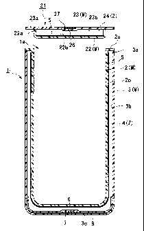
Brief Description of the Dra~~ings
Figure 1 is a cross-section of a vacuum flask and insulated lid showing an
example of
the transparent insulated container of the present invention.
Figure 2 is an outline drawing of the inner container on which a thermal
radiation
prevention layer has been formed.
Figure 3 is a drawing for explaining the structure of the thermal radiation
preventing
film.
CA 02274409 1999-06-07
Figure 4 is a drawing for explaining the initial condition for attaching the
thermal
radiation preventing film to the inner contailZer.
Figure 5 is a drawing for explaining the final condition for attaching the
thermal
radiation preventing film to the inner container.
Detailed Description of the Preferred Embodiments
An embodiment of the present invention will be explained with reference to
Figure 1.
Figure 1 shows a cross-section drawing of a wide-mouthed vacuum flask and an
insulated lid
which can be fitted over the mouth thereof, as an example of an insulated
container of the
present invention. Reference 1 is a wide-mouthed vacuum flask which is an
example of an
insulated container of the structure of the present invention. The mouth 1 a
of this vacuum
flask 1 is covered by an insulated lid 21 which can be removably attached and
which seals the
mouth 1 a.
The vacuum flask 1 comprises a double-walled structure which is formed by
arranging
the outer container 3 which is in contact with the atmosphere so that it
envelopes the inner
container 2 which is in contact with the food or drink stored therein when
food or drink is
stored in the vacuum flask 1. The rims of the mouths 2a and 3a of the inner
container and the
outer container respectively are joined to give a unified body. In addition, a
gas having low
thermal conductivity Z which has a thermal conductivity the same as air or
lower than air and
which comprises at least one gas from krypton, xenon, argon, or the like is
enclosed in the
space 4 which is foamed between the iluier container 2 and the outer container
3.
11
CA 02274409 1999-06-07
In addition, as the material from which the above mentioned inner and outer
containers
2 and 3 are formed, a transparent material M such as glass or synthetic resin
is used. From
among these transparent materials M, when synthetic resin is used, a synthetic
resin having
high gas barrier properties is preferable. In addition, more specifically, the
following synthetic
resins which have a gas permeability (based on ASTM D 1438-58) of 1.0
g/m2/241u-Jatm or less
(with respect to 02, N2, and C02) are preferable; for example, synthetic
resins such as methyl
methacrylate resin, polyethylene naphthalate resin, and polyacrylonitrile are
suitable, and
appropriately selecting and using one of these is preferable.
In addition, the insulating property of the vacuum flask of the present
invention is
improved by forming a thermal radiation preventing layer 5 on the surface of
at least one ofthe
outer surface 2b of the inner container 2 or the inner surface 3b of the outer
container 3 which
are on opposite sides of and face onto the space 4 which is formed between the
inner container
2 and the outer container 3. In Figure 1, this is arranged on the outer
surface 2b of the inner
container 2. However, this may also be the inner surface 3b of outer container
3. In addition,
the insulating effectiveness can be further improved by forming the thermal
radiation
preventing layer 5 on both the mutually opposing outer surface 2b of the inner
container 2 and
inner surface 3b of the outer container 3. In addition, the material used as
this thermal
radiation preventing layer 5 is a special feature of the present invention.
This material is a
material through which visible rays passes, and which absorbs or reflects
infra-red rays. This
material is suitably obtained using metal powders (Ag, Au, etc.), metal
oxides, or metal
nitrides, which may be deposited using vacuum deposition, sputtering or ion
plating, and it
12
CA 02274409 1999-06-07
may be single layered or multi-layered. In addition, deposition is also
possible by means of
coating, and the like, using organic coloring materials such as cyanine and
the like, or organic
metal complex salts.
By means of forming a laminate, it is possible for infra-red rays to be
absorbed or
reflected much more efficiently.
In addition, substances which use anthraquinone derivatives; substances
obtained by
dispersing ultra-fine powders of copper halides (copper (I)), or heat kneading
copper (II)
sulfide or copper (11) sulfide and thiourea derivatives and/or derivatives;
substances which use
a copper (II) sulfide and a photo reflecting frame can be used. Specifically,
antimony-doped
tin oxide (ATO), tin-doped indium oxide (TTO), and the like have infra-red
reflection rates
which are highly suitable. This can be formed by a deposition means such as
vacuum
deposition, sputtering, ion plating or the like.
It is not always necessary to form the above mentioned thermal radiation
preventing
layer 5 by directly forming the thermal radiation preventing membrane onto the
specified
opposing surfaces 2b or 3b of the inner and outer containers 2 and 3. As shown
in Figures 2
to 5, when the thermal radiation preventing film 31 is prepared in advance by
film formation
by means ofthe vacuum deposition, sputtering or ion plating of a material
which allows visible
rays to pass through and which absorbs or reflects infra-red rays, such as the
above mentioned
antimony-doped tin oxide, onto a transparent film 32, and this is then
disposed by wrapping it
around the surface 2b or the surface 3b which are on opposite sides of and
face onto the space
4 formed between the inner and outer containers 2 and 3, it is possible for
the thermal
13
CA 02274409 1999-06-07
radiation preventing layer 5 to be reliably provided and positioned with good
working
efficiency.
Moreover, since the materials for the thermal radiation preventing membrane
which
are deposited by means of vacuum deposition, sputtering or ion plating are
expensive, it is not
necessary for the thermal radiation preventing membrane to be deposited on
both surfaces of
the transparent film, it is sufficient for it to be formed on one side only.
Then, by positioning
the thermal radiation preventing membrane surface so that it faces toward the
space 4, the
thermal radiation prevention effect is the same as the effect achieved when
the membrane is
formed on both surfaces, and this has the advantage of low cost.
Since the thermal radiation preventing layer 5 of the present invention which
is formed
from the above-mentioned material is provided in the space in which the
insulation layer is
formed by enclosing a gas having low thermal conductivity Z such as krypton,
xenon, argon, or
the like, there are no factors which will cause deterioration of this thermal
radiation preventing
layer 5 since it is always exposed to an inert gas, such as laypton, xenon,
argon and the like,
which is a gas having low thermal conductivity Z. For this reason, it is not
necessary to provide
another substance as a protective coating layer over the thermal radiation
preventing layer 5.
Therefore, it is possible to obtain sufficient utilization of the infra-red
reflecting characteristic
which the thermal radiation preventing layer S intrinsically possesses.
In addition, reference 6 indicates an aperture which is provided in the bottom
3c ofthe
outer container 3 for the purpose of vacuum evacuating the space 4 and for
introducing a gas
having low thermal conductivit~~ Z into the space 4. Reference 7 indicates a
sealing plate for
14
CA 02274409 1999-06-07
blocking and sealing the above mentioned aperture 6, and it is preferable from
the point of
view of manufacturing that it be made using a material which is similar to
that of outer
container 3. Then, when this is bonded over the aperture G using an adhesive
and the aperture
is blocked, it is possible to reliably seal and block the aperture in an
extremely firm and air
tight manner. In addition, reference 8 is a protection cover for protecting
the bottom the
vacuum flask 1.
In the above, the structure of the vacuum flask 1 of the present invention was
explained, but it is also possible for the insulatiizg lid 21 which covers the
mouth 1 a of the
vacuum flask 1 to be formed having the same structure. Moreover, for
simplicity, structures of
insulating lid 21 which are identical to structures of the above mentioned
vacuum flask 1 are
indicated by references obtained by adding 20 to the references used to
indicate those
structures in the drawing of vacuum flask 1.
The insulating lid 21 is a double-walled lid formed by arranging an inner lid
container
22, which faces onto the contents of the container, and an outer lid container
23, which is
exposed to the atmosphere, leaving a space 24 therebetween, and then the inner
lid container
22 and the outer lid container 23 are formed into a single body by bonding the
rims of their
respective mouths 22a and 23a. The inner lid container 22 and the outer lid
container 23 are
made from a transparent material such as glass or synthetic resin. In
addition, an insulation
layer is formed by enclosing a gas having low thermal conductivity Z
comprising at least one
gas from krypton, xenon, and argon in the above mentioned space 24.
CA 02274409 1999-06-07
In addition, the insulating property is improved by forming a thermal
radiation
preventing layer 5 on the surface of at least one of the surfaces 22b or 23b
which are on
opposite sides of and face onto the space 24 which is formed between the inner
lid container
22 and the outer lid container 23. In Figure 1, this is arranged on the
surface 22b of the inner
lid container 22. However, this may also be the surface 23b of outer lid
container 23. In
addition, the insulating effectiveness can be further improved by forming the
thermal radiation
preventing layer 5 on both the mutually opposing surface 22b of the inner lid
container 22 and
surface 23b of the outer lid container 23. In addition, the material used as
this thermal
radiation preventing layer 5 is a special feature of the present invention.
This material is a
material through which visible rays can pass, and which absorbs or reflects
infra-red rays, and,
preferably, uses metal oxides, or metal compounds. More specifically, antimony-
doped tin
oxide, tin-doped indium oxide, and the like are suitable. In the same way as
for the above
mentioned vacuum flask 1, these can be formed by a deposition means such as
vacuum
deposition, sputtering, ion plating or the like.
It is not always necessary to form the above mentioned thermal radiation
preventing
layer 5 by directly forming the thermal radiation preventing membrane onto the
specific
opposing surfaces 22b or 23b of the inner lid container 22 and outer lid
container 23. As
shown in Figures 2 to 5, when the thermal radiation preventing film 31 is
prepared in advance
by film formation by means of the vacuum deposition, sputtering or ion plating
of a material
which allows visible rays to pass through and which absorbs or reflects infra-
red rays, such as
the above mentioned antimony-doped tin oxide, onto a transparent film 32, and
this is then
16
CA 02274409 1999-06-07
disposed by wrapping it around the surface 22b or the surface 23b which are on
opposite sides
of and face onto the space 24 formed between the inner lid container 22 and
outer lid
container 23, it is possible for the thermal radiation preventing layer 5 to
be reliably provided
and positioned with good working efficiency.
Moreover, since the materials for the thermal radiation preventing membrane
which
are deposited by means of vacuum deposition, sputtering or ion plating are
expensive, it is not
necessary for the thermal radiation preventing membrane to be deposited on
both surfaces of
the transparent film, it is suf~rcient for it to be formed on one side only.
Then, by positioning
the thermal radiation preventing membrane surface so that it faces toward the
space 24, the
thermal radiation prevention effect is the same as the effect achieved when
the membrane is
formed on both surfaces, and this has the advantage of low cost.
In addition, as the material from which the above mentioned inner lid
container 22 and
outer lid container 23 are formed, a transparent material M such as glass or
synthetic resin is
used. From among these transparent materials M, when synthetic resin is used,
a synthetic
resin having high gas barrier properties is preferable, in the same way as for
the above
mentioned vacuum flask 1. More specifically, the following synthetic resins
which have a gas
permeability (based on ASTM D 1438-58) of 1.0 g/m2/24hrlatm or less (with
respect to 02,
N2, and C02) are preferable; for example, synthetic resins such as methyl
methacrylate resin,
polyethylene naphthalate resin, and polyacrylonitrile are suitable, and
appropriately selecting
and using one of these is preferable.
17
CA 02274409 1999-06-07
In addition, reference 26 indicates an aperture which is provided in the outer
lid
container 23 for the propose of vacuum evacuating the space 24 and for
introducing a gas
having low thermal conductivity Z lllt0 the space 24. Reference 27 indicates a
sealing plate for
blocking and sealing the above mentioned aperture 26, and it is preferable
from the point of
view of manufacturing that it be made using a material which is similar to
that of outer lid
container 23. Then, when this is bonded over the aperture 26 using an adhesive
and the
aperhue is blocked, it is possible to reliably seal and block the aperture in
an extremely firm
and air tight manner.
The above mentioned thermal radiation preventing layer 5 of the present
invention may
be formed by directly depositing the above mentioned material, which allows
visible rays to
pass through but which absorbs or reflects infra-red rays, onto the outer
surface 2b of the inner
container 2 and the inner surface 3b of the outer container 3, and the surface
22b of inner lid
container 22 and surface 23b of outer lid container 23, which are on opposite
sides of and face
onto the space 24. However, by means of producing a thermal radiation
preventing film
separately in advance by forming a membrane of the material through which
visible rays can
pass and which absorbs or reflects infra-red rays onto a transparent film, and
then suitably
arranging this on each of the surfaces of the above mentioned inner and outer
containers,
working efficiency is improved because the formation operations for the
thermal radiation
preventing layer 5 are extremely easy, and accurate positioning is possible.
Next, the manufacturing method for the insulated container of the present
invention
will be explained using the above mentioned vacuum flask 1 shown in Figure 1
as an example.
18
CA 02274409 1999-06-07
Firstly, an inner container 2 beiizg a cylindrical body with a bottom and
having a
desired shape and an outer contaiizer 3 being a cylindrical body with a
bottom, having an
aperture in the bottom thereof, and having a shape slightly larger than the
above mentioned
inner container 2 are molded from a transparent material M such as, for
example, methyl
methacrylate resin. Then, a thermal radiation preventing layer 5 which absorbs
or reflects
infra-red rays and allows visible rays to pass through is formed on the outer
surface of the inner
container 2 (when the inner container 2 has been joined with the outer
container 3, this is the
outer surface 2b which faces toward the outer container 3 and which faces
space 4).
It is possible for this thermal radiation preventing layer 5 to be formed and
deposited
directly by means of vacuum deposition, sputtering, ion plating, or the like
of the membrane
material onto the surface 2b which is opposite the outer container 3 and which
faces onto the
space 4 as mentioned above. But it is not always necessary for the membrane to
be directly
deposited onto the surface 2b. For example, as shown in Figures 2 to 5, a
thermal radiation
preventing film 31 can be formed by means of vacuum deposition, sputtering,
ion plating, or
the like of the above mentioned material 33 which allows visible rays to pass
through and
which absorbs or reflects infra-red rays, such as antimony-doped tin oxide,
onto a transparent
film 32. This can then be wrapped around the surface 2b of the inner container
2 or the surface
3b of the outer container 3 which are on opposite sides of and face onto the
space 4, and
thereby workability may be improved.
In this situation, the thermal radiation preventing film 31 can be divided
into a piece for
use on the cylindrical part and a piece for use on the bottom part and then
positioned. By
19
CA 02274409 1999-06-07
means of dividing and then positioning in this way, it is possible to
appropriately position and
attach the thermal radiation preventing film 31 matching the shape of the
inner container 2
without the production ofwrinkles, and it is possible to make a shape with
which the contents
can be extremely well seen.
As the layer material, which allows visible rays to pass and which absorbs or
reflects
infra-red rays, of the thermal radiation preventing layer S, for example,
antimony-doped tin
oxide, tin-doped indium oxide, and the like are suitable.
The thermal radiation preventing layer 5 may be formed as a laminate in order
to
suitably absorb or reflect infi-a-red rays, by appropriately selecting the
above-mentioned
membrane materials.
In addition, as shown in Figures 2 to 5, when a thermal radiation preventing
film 31 is
formed by means of forming a membrane 33 of the layer material such as this
antimony-doped
tan oxide or tin-doped indium oxide on a transparent film 32 in advance, and
this thermal
radiation preventing film 31 is wrapped around the specified surface 2b of the
inner container
or the surface 3b of the outer container 3, thereby forming thermal radiation
preventing layer
5, the surface of the film on which the membrane has been formed is not
against the surface of
the container around which the film has been wrapped, it is effective for the
film to be provided
in such a way that it faces the space 4 side. As one example of this type of
thermal radiation
preventing film, heat mirror film (product name) manufactured by Mitsui
Chemical Co. Ltd. is
suitable for use. The percentage of visible rays which passes through this
film is about 45 to
CA 02274409 1999-06-07
80%, and the percentage of infra-red rays, which is related to heat, is a
value of about 75 to
90%.
Next, the inner container 2 is inserted into the outer container 3 and
arranged leaving
a space 4 between the inner container 2 and the outer contauzer 3, and a
single body is formed
by means of welding the rims of their mouths 2a and 3a using a vibration
welder or the like,
and thereby a container having a double walled structure is formed.
Next, the space 4 is vacuum evacuated via aperture 6 using an evacuation means
(not
shown in the Figures) such as a vacuum evacuation pump. Then, a gas having low
thermal
conductivity Z comprising at least one gas such as krypton, xenon, or argon is
introduced into
the space 4. Then, when it has been filled to a pressure equal to or slightly
higher than
atmospheric pressure, the aperture 6 is air-tightly sealed by bonding the
sealing plate 7 over
the above mentioned aperture 6.
Then, when this sealing plate 7 is bonded over the aperture 6 using an
adhesive, and the
aperture 6 is sealed, it is possible to make a fum and reliable seal which is
very air-tight.
In this way, a transparent insulated container like the vacuum flask 1 of the
present
invention can be manufactured, in addition, an explanation has been omitted,
but the
insulated lid 21 can be manufactured in the same way.
In addition, in the above-mentioned embodiment, the explanation was made using
a
vacuum flask as an example, however, the insulated container of the present
invention is not
limited to vacuum flasks alone. In addition to vacuum flasks, the present
invention may be
suitably adapted to any insulated container in which the insulation layer is
formed by means of
21
CA 02274409 1999-06-07
a double-walled structure in which a space is formed between an inner
container and an outer
container, such as cooler boxes, ice boxes, insulated cups, insulated
kitchenware, and
temperature maintaining lunch boxes. In addition, it can also be suitably
adapted to insulated
utensils such as insulated lids in which the insulation layer is formed by
means of a double-
walled structure.
In addition, in the above-mentioned embodiment, an example is given in which a
gas
having low thermal conductivity Z is introduced into the spaces 4 and 24,
however, it is of
course possible to apply the present invention to an insulated container
having a structure in
which the spaces 4 and 24 are filled with air, as long as there is a double-
walled structure
having insulating properties. In addition, the above mentioned space may also
be filled with a
silica-type solid insulating material which is clear.
Next, in the embodiment of the insulated container shown in the above-
mentioned
Figure 1, with regard to the forniation of the thermal radiation preventing
layer 5, a method
which is simpler and which has good efficiency will be explained using an
example of an
embodiment thereof shown in Figures 2 to 5. Structural parts shown in Figures
2 to S which
are the same as parts shown in Figure 1 are indicated with the same reference
and a detailed
description thereof is omitted.
Figure 2 is an outline drawing of an inner container 2 on which a thermal
radiation
preventing layer 5 is formed. In this embodiment, a thermal radiation
preventing layer 5 is
formed by means of wrapping and fixing a thermal radiation preventing film 31
which has been
manufactured separately onto the outer surface 2b of the inner container 2.
22
CA 02274409 1999-06-07
Moreover, it is not necessary for the film and the outer surface 2b to be
close and it is
preferable for there to be some gaps. In addition, as shown in Fiwre 3, this
thermal radiation
preventing film 31 is formed by depositing material which reflects or absorbs
infra-red rays as
a thermal radiation preventing membrane 33 by means of vacuum deposition,
sputtering, ion
plating or the like onto a transparent film 32 of synthetic resin which has an
approximately
rectangular shape i1i which the axial dimension and the circumferential
dimension of the inner
container are respectively taken as the length and width. As the material, for
example,
antimony-doped tin oxide (AOT), tin-doped indium oxide (ITO), and the like can
be suitably
used.
In addition, when the thermal radiation preventing film 31 is being arranged
on the
outer surface 2b of the inner container 2, the surface of the thermal
radiation preventing
membrane 33 is not in contact with the container surface 2b, it is arranged
and positioned on
the outer surface of the transparent film so that it always faces the space.
Therefore, a mark
31 a, such an L-shaped notch, for distinguishing the front from the back and
for determining
positioning is cut in a suitable place, and preferably in a corner, of the
thermal radiation
preventing film. Then the thermal radiation preventing film 31 is wrapped and
fixed around
the surface 2b of the inner container by positioning this mark 31 a for
distinguishing the front
from the back and for determiniilg positioning at a specified position (for
example, at the
mouth 2a) and such that the surface of the membrane 33 is to the outside. In
other words, if
this then:nal radiation preventing film 31 is positioned so that the surface
of the thermal
radiation preventing membrane 33 is reversed, the mark 31 a for distinguishing
the front from
23
CA 02274409 1999-06-07
the back and for determining positioning will be positioned in a different
position, and the
membrane 33 will be in a non-reflective symmetry.
In addition, it is preferable that there not be close contact between the
thermal
radiation preventing film 31 and the outer surface 2b of the inner container 2
and, from the
point of view of the insulation property, a gap of 0.1 to 3.0 mm is
preferable.
This type of thermal radiation preventing layer 5 is formed by means of a
positioning
operation process such as the following. This is explained with reference to
Figure 4 and
Figure 5.
Figure 4 is an outline diagram for explaining the condition at the initial
stage of the
positioning. Figure 5 is an outline diagram for explaining the condition at
the final stage ofthe
positioning. As shown in Figure 4, first, a mark 34, such as a ridge or a
groove, for determining
the initial position of the film is provided in the surface 2b of the inner
container 2 in the
up-down axis direction of the inner container 2. One edge 31 b of the thermal
radiation
preventing film 31 is arranged in a position with the above mentioned mark 31
a, for
distinguishing the front from the back and for determining positioning, at the
upper part ofthe
mouth 2a of the inner container, at the mark 34 for determining the initial
position of the film.
At this time and in this position, the mark 31 a, for distinguishing the front
from the back and
for determining positioning, is provided so that the thermal radiation
preventing membrane 33
of the thermal radiation preventing film 31 is on the outer surface of the
transparent film 32
which forms the base and so that it is not in contact with the outer surface
2b of the inner
container 2. For this reason, if the position is determined irl the above-
mentioned manner, the
2.4
CA 02274409 1999-06-07
thermal radiation preventing membrane 33 surface is arranged such that it is
always exposed
on the outer surface of the transparent film 32, on the outer surface 2b of
the inner container
2. In addition, if by any chance, by mistake, the thermal radiation preventing
membrane 33
surface of the thermal radiation preventing film 31 is positioned such that it
is in contact with
the outer surface 2b of the inner container 2, the position of the mark 31 a,
for distinguishing
the front from the back and for determining positioning, will be changed to
the bottom 2c of
the inner container 2, or the shape of the mark 31 a will be reversed or
upside down, therefore,
it will be possible to immediately determine that there has been a mistake in
the positioning.
Consequently, it is possible to position the thermal radiation preventing film
31 on the
outer surface 2b of the inner container 2 in a condition such that the
prevention membrane 33
surface is exposed to the outside, with out error, in a position which is more
effective for the
purpose of thermal radiation prevention.
Next, once the thermal radiation preventing film 31 is in the above-described
condition, one end 31 b thereof is attached and fixed to the outer surface 2b
of inner container
2 using a fixing means such as adhesive tape. Then, as shown in Figure 5, the
thermal radiation
preventing film 31 is wrapped once around the outer surface 2b of the inner
container 2, and
the other end 31 c of the thermal radiation preventing film 31 is attached and
fixed using a
fixing means such as an adhesive tape at the position of mark 34 for
determining the initial
position which is provided in the outer surface 2b of inner container 2. In
this way, as shown
in Figure 2, a thermal radiation preventing film 31 which is prepared in a
separate process can
CA 02274409 1999-06-07
be effectively positioned on the outer surface 2b of inner container 2, and
thereby an iru-rer
container 2 having a tl-rermal radiation preventing layer 5 can be made.
In the attachment and fixing of the thermal radiation preventing film 31 to
the outer
surface 2b of the inner container, double-sided adhesive tape is attached in
the axial direction
to the outer surface 2b of the inner container 2, one end 31 b of the thermal
radiation
preventing film 31 is stuck to a part of the double-sided tape, then the
thernal radiation
preventing film 31 is wrapped once around the outer surface 2b, the other end
31 c of the
thermal radiation preventing film 31 is stuck to the remaining part of the
double-sided tape,
and thereby the thernal radiation preventing film 31 can be fixed to the inner
container 2.
Moreover, when the above mentioned thermal radiation preventing film 31 is
arranged
by wrapping it around the outer surface 2b of inner container 2, with the
exception of both
ends of the above mentioned thermal radiation preventing film 31, it is not
necessary for the
surface ofthe thermal radiation preventing film 31 to be in contact with the
outer surface 2b of
the inner container 2, and it is preferable for there to be a gap of
approximately 0.1 to 3 mm
between the outer surface 2b and the film 31. By means of arranging thermal
radiation
preventing film 31 with a gap in this way, when a hot liquid is housed within
inner container
2, even if the external diameter of the inner container 2 increases due to
thermal expansion, the
exertion of tension on the thermal radiation preventing film 31 is prevented,
and thereby it is
possible to avoid the film breaking, and to prevent the film from separating
from the inner
container 2. In addition, it is also preferable from the point of view of the
insulating properties.
26
CA 02274409 1999-06-07
Using the same assembly method as explained 11 the above mentioned Figure 1,
this
inner container 2, on which a thermal radiation preventing film 31 has been
arranged and
which has been formed in the above-described way and as shown in Figure 2, is
put inside the
outer container 3, and arranged so that a space 4 is formed between inner
container 2 and outer
container 3, then the inner container 2 and the outer container 3 are joined
into a single body
by welding the rims of the mouths 2a and 3a thereof using a vibration welder
or the like, and
thereby a container having a double walled structure is formed.
Next, the space 4 is vacuum evacuated through the aperture 6 which is provided
in
outer container 3 by means of an evacuation means such as a vacuum evacuation
pump. Then
a gas having low thermal conductivity Z comprising at least one gas of
krypton, xenon, and
argon is introduced into space 4. Then, when the space 4 has been filled to a
pressure equal to
atmospheric pressure or slightly higher than atmospheric pressure, at normal
temperature, the
sealing plate 7 is placed over the above mentioned aperture 6 and adhered,
thereby the
aperture is air-tightly sealed.
In addition, when the sealing plate 7 is adhered using an adhesive, and the
aperture 6 is
sealed, it is possible to reliably and securely seal the aperture 6 in an
extremely air-tight
manner.
In addition, in the above-described embodiment, an example iii which the
thermal
radiation preventing layer 5 is formed on the outer surface 2b of inner
container 2 is explained,
however, it is possible to form the thermal radiation preventing layer 5 on
the inner surface 3b
of outer container 3 in the same way.
27
CA 02274409 1999-06-07
In the above, the manufacture of a transparent insulated container is
explained, but it is
also possible to manufacture an insulated lid using the same method. In
addition, in the above
mentioned embodiment, the explanation was made giving an example 11 WhlCh a
transparent
syntl-letic resin was used as the material for the inner container 2 and the
outer container 3,
however, the present invention is not limited to this, and in place of the
synthetic resin, it is of
course possible to use transparent glass for the inner container and the outer
container, and, in
the same way, obtain a transparent insulated container of the present
invention.
Moreover, in the above-mentioned manufacturing method, the formation of the
thermal radiation preventing layer 5 is explained using an example irl which a
transparent film
on which a thermal radiation preventing membrane has been deposited is used as
a thermal
radiation preventing film 31 and this is wrapped around and fixed to the
specified surface of
the inner container or the outer container. However, the present invention is
not limited to
this, and the same effects can be obtained by forming the dzermal radiation
preventing
membrane directly onto the specified surface of inner container or the outer
container.
Furthermore, in order to obtain an appropriate amount of absorption or
reflection of
the infra-red rays, the thermal radiation preventing layer S can be formed
using different
preventing membrane materials for the laminate.
A transparent container and lid having a structure like drat of the present
invention as
described above, when in use, is used to house liquid drinks and solid or semi-
solid foods, and
since the insulation layer is arranged with a thermal radiation preventing
layer 5 which blocks
infra-red rays and allows visible rays to pass through, it is possible to see
through the side
28
CA 02274409 1999-06-07
surfaces and visually check the inside of the container. Consequently, with
the transparent
insulated container of the present invention, it is possible to check the
amount (for example,
the amount of a liquid) of the contents housed 11 the container, changes in
the conditions of
the contents (for example, how much ice has melted), and the like from the
side without
removing the insulated lid which covers the mouth. For this reason, since it
is not necessary to
open the mouth of the insulated container for the purpose of checking the
condition of the
contents, the amount of heat lost or gained through the mouth is reduced, and
the superior
insulating property which the insulated container intrinsically has can be
maintained.
In addition, the structure of the insulated container of the present invention
is
extremely simple having only a container having a double-walled structure in
which inner and
outer containers of a transparent material are arranged with a space
therebetween and joined
into a single body, a thermal radiation preventing membrane which absorbs and
reflects
infix-red rays and allows visible rays to pass through, and, when necessary,
the above
mentioned space is filled with a gas having low thermal conductivity or is
evacuated.
Therefore, manufacture is easy, manufacturing costs can be reduced, and this
is ideal for mass
production.
Furthermore, since the thermal radiation preventing layer 5 is formed by
manufacturing a thermal radiation preventing film 31 in which a separate
thermal radiation
preventing membrane 33 has been deposited on a transparent film and then this
is wrapped
around the outer surface 2b of inner container 2, work operations are
simplified, continuous
29
CA 02274409 1999-06-07
assembly is possible, and extremely remarkable results with respect to
production for the
purposes of commercialization are realized.
Next, in order to confirm the properties of the transparent insulated
container of the
present invention, the following tests were conducted:
(1 ) With regard to the transparent insulated container, the materials of the
inner and
outer containers (difference in the amount of visible rays which passes
through), the material
and the thermal radiation preventing layer which allows visible rays to pass
through and which
absorbs or reflects infra-red rays, and the like were differed and various
transparent insulated
containers were manufactured (Embodiments 1 through 3). Then, in order to
clarify the
properties of the transparent insulated containers of the present invention of
Example 1,
Example 2, and Example 3, conventional insulated containers were manufactured
in which
non-transparent thermal radiation preventing layers were provided, or in which
a thermal
radiation preventing layer was not provided so that the inside could be seen
(Comparative
Example 1 to Comparative Example 3). The temperature maintaining properties
due to this
differences were then compared.
The dimensions of each of the manufactured insulated containers of Example 1,
Example 2 and Example 3 and the each of the Comparative Examples 1 to 3 were
the same and
were as follows.
(Common Dimensions of the Manufactured Insulated Containers]
CA 02274409 1999-06-07
* Inner container 2: inner diameter 90 mm; wall thiclrness: 2.5 mm; height:
235 mm; capacity:
1000 cc.
* Outer container 3: external diameter 110 mm; wall thicl~ess: 2.5 mm.
* Space 4: width of space: 5 mm.
[Example 1 ]
As Example 1, a transparent insulated container formed from a synthetic resin
of the
present invention was manufactured in the following way.
* Material of the inner and outer containers 2 and 3: methyl methacrylate
resin (transmissivity
with respect to visible rays: approximately 95%)
* Thermal radiation preventing layer 5: A film "heat mirror 66" (product name)
which had
been given a metal sputtering treatment, manufactured by Mitsui Chemicals Co.
Ltd., was
adhered to the outer surface 2b of inner container 2 which faces the space 4.
* Gas Z which was introduced into space 4: The space was filled with laypton
gas to
approximately atmospheric pressure.
* Sealing of aperture 6: A polyethylene naphthalate was used as the sealing
plate 7, and this
was adhered and the aperture sealed using an adhesive.
[Example 2]
31
CA 02274409 1999-06-07
As Example 2, an insulated container was manufactured with the material used
in
Example 1 to make the inner and outer containers and the material used in
Example 1 for die
thermal radiation preventing layer being replaced in the following way.
* Material of the inner and outer containers 2 and 3: polyethylene naphthalate
(transmissivity
with respect to visible rays: approximately 80%)
* Thermal radiation preventing layer 5: A film "heat mirror 44" (product name)
which had
been given a metal sputtering treatment, manufactured by Mitsui Chemicals Co.
Ltd., was
adhered to the outer surface 2b of inner container 2 which faces the space 4
* Gas Z which was introduced into space 4: The space was filled with krypton
gas to
approximately atmospheric pressure.
* Sealing of aperture 6: A polyethylene naphthalate was used as the sealing
plate 7, and this
was adhered and the aperture sealed uslllg an adhesive.
[Example 3)
As Example 3, an insulated container, as follows, was manufactured using the
same
material for the inner and outer containers 2 and 3 and the same material for
the thermal
radiation preventing layer as were used in Example 2, while the laypton gas
enclosed in space
4 was replaced using air.
* Material of the inner and outer containers 2 and 3: polyethylene naphthalate
(transmissivity
with respect to visible rays: approximately 80%)
32
CA 02274409 1999-06-07
* Thermal radiation preventing layer 5: A film "heat mirror 44" (product name)
which had
been given a metal sputtering treatment, manufactured by Mitsui Chemicals Co.
Ltd., was
adhered to the outer surface 2b of inner container 2 which faces the space 4.
* Gas Z which was introduced into space 4: The space was filled with air to
approximately
atmospheric pressure.
Moreover, with regard to the films "heat mirror 66" and "heat mirror 44" on
which a
metal sputtering process had been conducted and which were used as the thermal
radiation
preventing layer 5 in Example 1, Example 2, and Example 3, the
transmissibility with regard
to visible rays for "heat mirror 66" (about 70%) was greater than that of
"heat mirror 44"
(approximately 45%); and the transmissibility with regard to near infra-red
rays for "heat
mirror 66" (approximately 20% or less) was greater than that for "heat mirror
44" (about 10%
or less).
* Sealing of aperture 6: A polyethylene naphthalate was used as the sealing
plate 7, and this
was adhered and the aperture sealed using an adhesive.
Next, the following insulation containers of Comparative Examples 1 to 3 were
manufactured for the purpose of comparison. The dimensions are the same as
those of
Example 1 to Example 3 as described above.
[Comparative Example 1 ]
33
CA 02274409 1999-06-07
As Comparative Example 1, an insulated container, as follows, was manufactured
llSlllg, as the thermal radiation preventing layer 5, aluminum foil which is
generally used in
various conventional insulated containers.
* Material of the inner and outer containers 2 and 3: polyethylene naphthalate
(transmissivity
with respect to visible rays: approximately 80%)
* Thermal radiation preventing layer 5: Aluminum foil was adhered to the outer
surface 2b of
inner container 2 which faces the space 4
* Gas Z which was introduced into space 4: The space was filled with laypton
gas to
approximately atmospheric pressure.
* Sealing of aperture 6: A polyethylene naphthalate was used as the sealing
plate 7, and this
was adhered and the aperture sealed using an adhesive.
[Comparative Example 2J
As Comparative Example 2, the following insulated container which is the same
as the
insulated container of Comparative Example 1 without the thermal radiation
preventing layer
was manufactured.
* Material of the inner and outer containers 2 and 3: polyethylene naphthalate
(transmissivity
with respect to visible rays: approximately 80%)
* Thermal radiation preventing layer 5: none
* Gas Z which was introduced into space 4: The space was filled with lQypton
gas to
approximately atmospheric pressure.
34
CA 02274409 1999-06-07
* Sealing of aperture 6: A polyethylene naphthalate was used as the sealing
plate 7, and W is
was adhered and the aperture sealed using an adhesive.
[Comparative Example 3]
As Comparative Example 3, as follows, an insulated container the same as in
Comparative Example 2 was manufactured with air being enclosed in the space 4
in place of
laypton.
* Material of the inner and outer containers 2 and 3: polyethylene naphthalate
(transmissivity
with respect to visible rays: approximately 80%)
* Thermal radiation preventing layer 5: none
* Gas Z which was introduced into space 4: The space was filled with air to
approximately
atmospheric pressure.
'~ Sealing of aperture 6: A polyethylene naphthalate was used as the sealing
plate 7, and this
was adhered and the aperture sealed using an adhesive.
In Table 1, the temperature maintaining properties of the transparent
insulated
containers of the present invention of Example 1, Example 2 and Example 3 are
shown and
compared with the temperature maintaining properties of the insulated
containers according to
Comparative Examples 1 to 3.
The temperature maintaining properties were measured by putting 1000 cc of hot
water
of 95°C into the inner container 2, then closing the mouth with a
styrene foam lid of 30 mm in
CA 02274409 1999-06-07
thickness, and then measuring the temperature after the passage of 2 hours.
The atmosphere
was maintained at a temperature of 20 °C all the time in conditions
without wind.
Table 1
Insulated Insulated
Containers Containers
of the of the
Present Comparative
Invention Exam les
Example Example Example ComparativeComparativeComparative
1 2 3
Exam le Exam le Exam le
1 2 3
Temperature7 5 7 6 7 0 7 5 64 61
after 2
hours
C
Visual Yes yes yes no Yes yes
Inspection
Possible
As is clear from Table I
The insulated containers of the present invention of Example 1 and Example 2
are not
in the slightest bit inferior with respect to the temperature maintaining
properties (7 5°) of the
insulated container of Comparative Example 1 which uses aluminum foil as the
thermal
radiation preventing layer and which has excellent properties as a
conventional insulated
container ofthis type. Example 1 displayed an ability to maintain the
temperature at 75°C and
Example 2 displayed an ability to maintain the temperature at 76°C. In
addition, in the
insulated container of Comparative Example 1, the inside of the container was
blocked by the
aluminum foil and visual inspection was not possible. In contrast, it was
possible to inspect
the level of the hot water stored in the insulated containers of Example l and
Example 2.
36
CA 02274409 1999-06-07
02 In addition, while the insulated container of Example 3 (in which air is
enclosed in the
space in place of the gas having low thermal conductivity such as the krypton
of the above
mentioned Example 1 and Example 2) of the present invention displayed an
ability to
maintain the temperature at 70°C which is inferior to that of the
Example 1 and Example 2, it
is still a temperature maintaining ability which is satisfactory for use, and
furthermore the
contents of the container are visible.
03 In addition, when Example 1 and Example 2 are compared 'vvith Example 3,
for
improving the temperature maintaining property, it is, as might be expected,
preferable to
enclose a gas having thermal conductivity such as krypton in the space.
~ In addition, with regard to the insulated containers of Example 1, Example 2
and
Example 3 in which the thermal radiation preventing layer of the present
invention is
provided, the insulated containers of Comparative Example 2 and Comparative
Example 3 (in
which a thermal radiation preventing layer was not provided in order to make
visual inspection
possible) displayed an ability to maintain the temperature at 64°C
(Comparative Example 2)
and 61 ° C (Comparative Example 3) indicating that the temperature
maintaining property is
extremely degraded. Thereby, it is possible to confirm that the effect of the
thermal radiation
preventing layer of the present invention is extremely large.
(2) Next, a transparent insulation lid based on the present invention was
manufactured
(Example 4) and, in order to compare the properties thereof, an insulated lid
having a structure
in which a thermal radiation preventing layer was not provided, and an
insulated lid of
37
CA 02274409 1999-06-07
conventional foam styrene (Comparative Example 4 and Comparative Example 5)
were
manufactured, and compared.
[Example 4]
An insulated lid according to the present invention as below was manufactured.
* Inner lid container 22: external diameter: 203 mm, inner diameter: 197 mm,
depth: 5 mm,
thickness: 3 mm
Methyl methacrylate resin (transmissivity with respect to visible rays:
approximately 95%)
was used as the material.
* Outer lid container 23: diameter: 220 mm, thiclazess: 3 mm; from a disk-
shaped mold
Methyl methacrylate resin (transmissivity with respect to visible rays:
approximately 95%)
was used as the material.
* Space 24: thickness: 5 mm
The space was filled with krypton gas as the gas having low thermal
conductivity to
approximately atmospheric pressure.
* Thermal radiation preventing layer 5: A film "heat minor 66" (product name)
which had
been given a metal sputtering treatment, manufactured by Mitsui Chemicals Co.
Ltd., was
adhered to the surface 22b of inner lid container 22 which faces the space 24.
* Sealing of aperture 6: A polyethylene naphthalate was used as the sealing
plate 7, and this
was adhered and the aperture sealed using an adhesive.
38
CA 02274409 1999-06-07
[Comparative Example 4J
As Comparative Example 4, an insulated lid not provided with a thermal
radiation
preventing layer 5 but otherwise having the same conformation, such as
materials, dimensions,
and the like, as Example 4 was manufactured.
[Comparative Example 5]
As Comparative Example 5, a foam styrene lid having a thickness of 20 mm and a
diameter of 203 mm and not having a thermal radiation preventing layer 5 was
manufactured.
In order to test the temperature maintaining property of the transparent
insulated lid of
the above mentioned Example 4 which is based on the present invention, a
stainless steel
insulated vacuum flask having a double-walled structure, a shape as shown in
Figure 1 and the
following dimensions was used and the temperature maintaining ability was
measured.
* Material of the inner and outer containers: stainless steel, thickness of
the wall of the inner
container: 0.4 mm, thickness of the wall of the outer container: 0.8 mm.
* Dimensions of the inner container: mouth diameter: 205 mm; depth: 130 mm;
actual
capacity: approximately 4000 cc.
* Insulation layer wall: space: 6.3 mm, evacuated to a vacuum of 10-3 Torr or
less.
3500 cc of hot water at a temperature of 95° C were put into this
insulated container,
the mouth was respectively covered with the insulated lid of the above
mentioned Example 4,
39
CA 02274409 1999-06-07
and of the above mentioned Comparative Example 4 and Comparative Example 5,
for the
purposes of comparison. After 6 hours, the change in temperature of the above
mentioned hot
water was measured. As the results thereof, in Table 2, the temperature
maintaining ability
after the passage of 6 hours for Example 4 of the present invention are shown
and compared
with the temperature maintaining ability of the insulated lids of Comparative
Example 4 and
Comparative Example 5, for the purposes of comparison.
In addition, the atmosphere was always maintained at a temperature of
20° C in
conditions without wind.
Table 2
Insulated Lid Insulated Lids
of d1e of the Comparative
Examples
Present Invention
Exam le 4 Com arative Exam Com arative Exam
le 4 le 5
Temperature 73 65 72
after 6
hours C
Visual inspectionyes Yes No
ossible
Thickness of 5 5 20
insulation layer
mm
As is clear from Table 2, the insulated lid of Example 4 in which a thermal
radiation
preventing layer 5 according to the present invention was provided displayed
an ability to
maintain the temperature at 73° C , and the insulated lid of
Comparative Example 4 iii which
a thermal radiation preventing layer 5 was not provided displayed an ability
to maintain the
temperature at 65° C. A very large difference in the temperature
maintaining ability was
CA 02274409 1999-06-07
produced and the effectiveness of the provision of the thermal radiation
preventing layer 5 was
confirmed. In addition, the temperature maiiztaining ability of the insulation
lid of Example 4
of the present invention (which demonstrated an ability to maintain the
temperature at 73°
C) is approximately the same as or better than the temperature maintaining
ability of the
insulated lid of Comparative Example 5 (which demonstrated an ability to
maintain the
temperature at 72° C) which uses foam styrene which is generally used
as a conventional
insulating material. The insulated lid of the above mentioned Example 4 of the
present
invention gives the remarkable effects of making it possible to have a
thickness of 5 mm which
is much thinner than the 20 mm thickness of the insulated lid of convention
foam styrene of
Example 5, as well as making visual inspection of the inside possible.
Moreover, in the above-described embodiments, the explanation was given in
which
the thermal radiation preventing layer 5 was formed on the outer surface 2b of
inner container
2, but it is also possible to obtain the same actions and effects by forming
the thermal radiation
preventing layer 5 on the inner surface 3b of the outer container 3, and even
better effects are
exhibited if the thermal radiation preventing layer 5 is formed on the
surfaces of both walls.
Moreover, in the above-mentioned manufacturing method, the formation of the
thermal radiation preventing layer 5 is explained using an example in which a
transparent film
on which a thermal radiation preventing membrane had been deposited was used
as a thermal
radiation preventing film and this was wrapped around and fixed to the
specified surface of the
inner container or the outer container. However, the present invention is not
limited to this,
41
CA 02274409 1999-06-07
and naturally the same effects can be obtained by forming the thermal
radiation preventilig
membrane directly onto the specified surface of the inner container or the
outer container.
In each of the above-described embodiments, explanation has been given using a
vacuum flask as the insulated container, but the present invention is not
limited to this alone.
In addition to vacuum flasks, the present invention may be suitably adapted to
any insulated
container in which the insulation layer is formed by means of a double-walled
structure in
which a space is formed between an inner container and an outer container,
such as cooler
boxes, ice boxes, insulated cups, insulated kitchenware, and temperature
maintaining lunch
boxes. In addition, it can also be suitably adapted to insulated utensils such
as insulated lids
in which the insulation layer is formed by means of a double-walled structure.
In addition, in each of the above-described embodiments explanation was given
using
tc~ansparent synthetic resin as the material of the inner and outer containers
which form the
insulated container, but the present invention is not limited to this. Any
material as long as it
is a transparent material, such as glass, can naturally be adapted, and the
same actions and
effects can be obtained.
42