Language selection

Search

Patent 2274501 Summary

Third-party information liability

Some of the information on this Web page has been provided by external sources. The Government of Canada is not responsible for the accuracy, reliability or currency of the information supplied by external sources. Users wishing to rely upon this information should consult directly with the source of the information. Content provided by external sources is not subject to official languages, privacy and accessibility requirements.

Claims and Abstract availability

Any discrepancies in the text and image of the Claims and Abstract are due to differing posting times. Text of the Claims and Abstract are posted:

  • At the time the application is open to public inspection;
  • At the time of issue of the patent (grant).
(12) Patent Application: (11) CA 2274501
(54) English Title: ASSEMBLY OF NUCLEAR FUEL RODS BUNDLE
(54) French Title: ENSEMBLE DE FAISCEAUX DE BARRES DE COMBUSTIBLES NUCLEAIRES
Status: Deemed Abandoned and Beyond the Period of Reinstatement - Pending Response to Notice of Disregarded Communication
Bibliographic Data
(51) International Patent Classification (IPC):
  • G21C 3/334 (2006.01)
  • G21C 21/02 (2006.01)
(72) Inventors :
  • BRIDGES, MICHAEL KEVIN (United Kingdom)
  • DESBOROUGH, PAUL HUGH (United Kingdom)
  • WIGG, GRAEME MICHAEL (United Kingdom)
(73) Owners :
  • BRITISH NUCLEAR FUELS PLC
(71) Applicants :
  • BRITISH NUCLEAR FUELS PLC (United Kingdom)
(74) Agent: LONG AND CAMERON
(74) Associate agent:
(45) Issued:
(86) PCT Filing Date: 1997-12-03
(87) Open to Public Inspection: 1998-06-18
Availability of licence: N/A
Dedicated to the Public: N/A
(25) Language of filing: English

Patent Cooperation Treaty (PCT): Yes
(86) PCT Filing Number: PCT/GB1997/003341
(87) International Publication Number: WO 1998026425
(85) National Entry: 1999-06-04

(30) Application Priority Data:
Application No. Country/Territory Date
9625517.9 (United Kingdom) 1996-12-09

Abstracts

English Abstract


A puller rod (1) is provided for use in assembling a nuclear fuel element by
loading nuclear fuel rods containing nuclear fuel pellets into a support
skeleton in the form of spaced apart grids. The puller rod (1) has a tubular
body in which at least a forward or leading portion of the body is made of
carbon fibre.


French Abstract

L'invention concerne une barre d'extraction (1) pour permettre l'assemblage d'un élément de combustible nucléaire en chargeant les barres de combustible nucléaires comprenant des pastilles de combustible à l'intérieur d'une structure de soutien en forme de grilles espacées. La barre d'extraction (1) possède un corps tubulaire dans lequel au moins une partie antérieure est fabriquée en fibre de carbone.

Claims

Note: Claims are shown in the official language in which they were submitted.

CLAIMS
1. A puller rod for use in assembling a nuclear fuel element by loading
nuclear
fuel rods containing nuclear fuel pellets into a support skeleton in the form
of spaced
apart grids, the apparatus comprising a puller rod having a tubular body in
which at
least a forward or leading portion of said body is made of carbon fibre.
2. A puller rod as in Claim 1 in which the portion of the puller rod made of
carbon fibre has a length at least equal to the length between adjacent grids
in the
support skeleton.
3. A puller rod as in Claim 1 or Claim 2 in which the outer surface of the
carbon
fibre portion of the puller rod is coated with a protective coating.
4. A puller rod as in Claim 3 in which the protective coating is a metal
plating.
5. A puller rod as in Claim 4 in which the metal plating is an electro-less
nickel
plating or chromium plating.
4

Description

Note: Descriptions are shown in the official language in which they were submitted.


CA 02274501 1999-06-04
WO 98126425 PCT/GB97/03341
ASSEMBLY OF NUCLEAR FUEL RODS BUNDLE
FIELD OF THE INVENTION
This invention relates to apparatus for building nuclear fuel elements in
which a
plurality of nuclear fuel rods, containing nuclear fuel pellets, are loaded
into support
skeletons in the form of spaced apart grids. By way of example, this invention
relates to the assembly of fuel elements for use in a Pressurised Water
Reactor
(PWR) which makes use of fuel rods that are both long and slender. If such
rods
were to be pushed into the skeleton, they would tend to buckle due to their
inherent
weakness. Accordingly, they are in fact loaded into the skeleton by pulling
them. In
order to achieve this, a device known as a pulley rod is used. The pulley rod
is passed
through the grids of the skeleton and the lead end is caused to engage an end
of the
fuel rod. The pulley rod is then pulled back through the skeleton, thereby
pulling the
fuel rod into position within the skeleton. The present invention is
particularly
concerned with pulley rods.
BACKGROUND OF THE INVENTION
A pulley rod is known in the form of a sleeve carrying a locking rod down its
centre.
Both the sleeve and the locking rod are long enough to reach through a fuel
skeleton
and attach via a collet to the bottom end plug of a fuel rod. The collet is an
externally profiled cylinder which is axially split from one end to provide
three
prongs or tines. These tines are normally close together allowing them to
enter the
end cap on a fuel rod. They are then forced apart and held open inside the end
plug
by the locking rod being moved forward down the centre of the collet, thereby
stopping it closing again. Once the pulley rod has pulled the fuel rod into
position
within the skeleton, the locking rod is pulled away from the collet allowing
the tines
to close together again and the pulley rod to be removed from the fuel rod.
The pulley rod typically comprises a steel tube of metallic material. In terms
of
dimensions, a typical pulley rod might be 4m in length and about 8mm in
diameter
and, because of its length and slenderness, it has a large inherent
deformation. This

CA 02274501 1999-06-04
WO 98/26425 PCT/GB97103341
deformation continues throughout its period of use due to the significant
deflection
forces during loading.
During the passage of the pulley rod through the skeleton, in order to link up
with the
fuel rod, the lead end of the pulley rod is unsupported for a distance which,
at its
maximum, is the distance between adjacent grids of the skeleton. This distance
may
be of the order of O.Sm and can be sufficient for the leading end of the
pulley rod,
which is unsupported, to droop sufficiently for it to become misaligned and,
therefore, for its front end not to enter the hole or cell in the next grid.
Instead, the
front end of the pulley rod will strike the cell wall and be damaged, or
damage the
grid, or both.
STATEMENTS OF INVENTION
According to the present invention there is provided a pulley rod having a
tubular
body, at least the forward or leading portion of said body being made of
carbon fibre.
A pulley rod of the present invention may include a tubular body made entirely
of
carbon fibre. However, it is preferred that only the leading or forward
section of the
tubular body be made of carbon fibre since it is the leading end, carrying the
collet
which is cantilevered as the rod advances from one grid in the skeleton to the
next.
More preferably, the length of the tubular body of the pulley rod made of
carbon fibre
is at least the length between adjacent grids in the skeleton. For instance,
the carbon
fibre length may be approximately equal to the separation of the adjacent
grids.
It is also preferred to coat the outer surface of the carbon fibre portion of
the pulley
rod with a protective coating in order to reduce wear on the rod while it is
in use and
to prevent carbon being transferred from the pulley rod to the skeleton grids
during
the passage of the pulley rod through the skeleton.
2

CA 02274501 1999-06-04
WO 98/26425 PCTIGB97103341
Preferably, the protective coating is a metal plating such as electro-less
nickel plating
or chromium plating.
BRIEF DESCRIPTION OF THE DRAWINGS
The accompanying drawings further illustrate the present invention and are as
follows:-
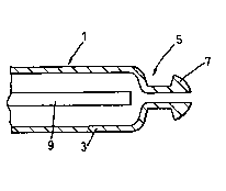
Figure 1 shows the forward or leading end of a pulley rod; and
Figure 2 illustrates the forces acting on a pulley rod while it is in use.
DESCRIPTION OF THE EMBODIMENT SHOWN IN THE DRAWINGS
There is illustrated in Figure 1 the leading or forward end of a pulley rod 1
which is
in the form of a tube 3 having a collet 5 provided with tines 7. Located
within tube 3
is a rod 9 which, in use, is moved forward relative to tube 3 in order to
force apart
tines 7 when the pulley rod has engaged the end of a fuel rod.
The tube 3 of pulley rod 1 is formed partly of steel and partly of carbon
fibre. The
carbon fibre section is the forward or leading end of the pulley rod and
extends over
about one third of its length. This carbon fibre section is chromium plated on
its
outer surface.
Referring to Figure 2 of the accompanying drawings, there are illustrated the
forces
acting on a pulley rod which, in use, may be described as a propped cantilever
with an
end load. The deflection at the end of the pulley rod is a function of the
length of the
pulley rod and the position of the prop during operation. It has been found
that, by
the addition of a downward force over the critical section on the top of the
pulley rod,
the deflection at the end of the rod is minimised, allowing the threading of
the pulley
rod through the skeleton without manual intervention. The provision of a
forward
carbon section to replace the normal steel tubular rod over this forward
portion
achieves the same effect, namely, the reducing to a minimum of the deflection
of the
end of the rod.
3

Representative Drawing
A single figure which represents the drawing illustrating the invention.
Administrative Status

2024-08-01:As part of the Next Generation Patents (NGP) transition, the Canadian Patents Database (CPD) now contains a more detailed Event History, which replicates the Event Log of our new back-office solution.

Please note that "Inactive:" events refers to events no longer in use in our new back-office solution.

For a clearer understanding of the status of the application/patent presented on this page, the site Disclaimer , as well as the definitions for Patent , Event History , Maintenance Fee  and Payment History  should be consulted.

Event History

Description Date
Appointment of Agent Requirements Determined Compliant 2020-09-02
Revocation of Agent Requirements Determined Compliant 2020-09-02
Revocation of Agent Requirements Determined Compliant 2020-09-01
Appointment of Agent Requirements Determined Compliant 2020-09-01
Time Limit for Reversal Expired 2002-12-03
Application Not Reinstated by Deadline 2002-12-03
Deemed Abandoned - Failure to Respond to Maintenance Fee Notice 2001-12-03
Letter Sent 1999-12-10
Inactive: Single transfer 1999-11-04
Inactive: Cover page published 1999-08-31
Inactive: IPC assigned 1999-08-30
Inactive: First IPC assigned 1999-08-10
Inactive: Courtesy letter - Evidence 1999-07-27
Inactive: Notice - National entry - No RFE 1999-07-21
Application Received - PCT 1999-07-16
Application Published (Open to Public Inspection) 1998-06-18

Abandonment History

Abandonment Date Reason Reinstatement Date
2001-12-03

Maintenance Fee

The last payment was received on 2000-11-22

Note : If the full payment has not been received on or before the date indicated, a further fee may be required which may be one of the following

  • the reinstatement fee;
  • the late payment fee; or
  • additional fee to reverse deemed expiry.

Please refer to the CIPO Patent Fees web page to see all current fee amounts.

Fee History

Fee Type Anniversary Year Due Date Paid Date
Basic national fee - standard 1999-06-04
Registration of a document 1999-11-04
MF (application, 2nd anniv.) - standard 02 1999-12-03 1999-11-23
MF (application, 3rd anniv.) - standard 03 2000-12-04 2000-11-22
Owners on Record

Note: Records showing the ownership history in alphabetical order.

Current Owners on Record
BRITISH NUCLEAR FUELS PLC
Past Owners on Record
GRAEME MICHAEL WIGG
MICHAEL KEVIN BRIDGES
PAUL HUGH DESBOROUGH
Past Owners that do not appear in the "Owners on Record" listing will appear in other documentation within the application.
Documents

To view selected files, please enter reCAPTCHA code :


To view images, click a link in the Document Description column. To download the documents, select one or more checkboxes in the first column and then click the "Download Selected in PDF format (Zip Archive)" or the "Download Selected as Single PDF" button.

List of published and non-published patent-specific documents on the CPD .

If you have any difficulty accessing content, you can call the Client Service Centre at 1-866-997-1936 or send them an e-mail at CIPO Client Service Centre.


Document
Description 
Date
(yyyy-mm-dd) 
Number of pages   Size of Image (KB) 
Representative drawing 1999-08-30 1 2
Abstract 1999-06-04 1 49
Description 1999-06-04 3 136
Claims 1999-06-04 1 21
Drawings 1999-06-04 1 14
Cover Page 1999-08-30 1 31
Reminder of maintenance fee due 1999-08-04 1 114
Notice of National Entry 1999-07-21 1 208
Courtesy - Certificate of registration (related document(s)) 1999-12-10 1 115
Courtesy - Abandonment Letter (Maintenance Fee) 2001-12-31 1 182
Reminder - Request for Examination 2002-08-06 1 128
PCT 1999-06-04 9 309
Correspondence 1999-07-26 1 30
Fees 1999-11-23 1 31
Fees 2000-11-22 1 36