Note: Descriptions are shown in the official language in which they were submitted.
CA 02274683 1999-06-10
WO 98/25684 PCT/BG97/00012
APPARATUS FOR CONTINUOUS PURIFICATION OF LIQUIDS, DEWATERING AND DRYING OF THE
SEPARATED
SOLIDS
FIELD OF THE INVENTION
The invention relates to an apparatus for continuous purification of liquids,
dewatering and drying of the separated non-filtering solids.
DESCRIPTION OF PRIOR ART
No apparatus is known for continuous purification of liquids and
dewatering and drying of the separated non-filtering solids in which the non-
filtering solids are accumulated in the inflowing liquid to be purified thus
forming a
mixture (suspension) which is dewatered and dried after reaching a definite
density.
(The proposed invention consists basically of functionally interconnected
belt filter and elastic thermo-filter press, and we will therefore consider
the
already known similar apparata.)
A belt filter is known (US Pat. No. 4212745, YeHesma) which comprises a
filter belt, moving synchronously upon two conveyor belts, located in sequence
one after another.
The conveyor belts are sliding on the upper part of two unloading blocks
connected to vacuum pumps and outlet pipes effecting the filtration process.
A disadvantage of this belt filter is the complicated synchronization
required to be maintained during the movement of the filter and conveyor
belts.
Another disadvantage is that in the described structure no hydrostatic
pressure can be exerted on the filter belt, which hydrostatic pressure would
speed up the filtration process.
A further disadvantage of this belt filter is that only the upper surface of
the
two unloading blocks is used and thus the capacity of the filtered liquid is
reduced significantly.
Still another drawback of this belt filter is that the unloading of the
dewatered cake is effected by scraping of the filter belt which lead to a
rapid
wear of the filter cloth, reduces its operating life and impairs the
filtration process.
CA 02274683 1999-06-10
WO 98/25684 PCTBG97/00012
2
A belt filter acting by subpressure - vacuum (EP 0391091 A1, Teckentrup)
Heinrich) is known, comprising a container of a definite volume, where the
suspension to be filtered flows in. A closed chamber connected to the vacuum
pump is located on the bottom of the container. There are apertures at the
upper
portion of the chamber. A drain belt lies over these apertures, and over the
drain
belt there is a continuous filter belt. The filtered liquid is carried out by
vacuum
from the closed chamber, and the residual cake on the filter belt is separated
by
means of a rotating brush ands is disposed of through an appropriate hole.
A disadvantage of the belt filter with subpressure is that only the upper
surface of the closed chamber is employed for filtration and therefore the
filtering
capacity is diminished considerably.
A further drawback of the belt filter with subpressure is that not more than
one chamber can be used with it. This leads to a manifold reduction of the
amount of filtered liquid and the capacity of the belt
filter.
Another disadvantage of the belt filter with subpressure is that it cannot act
as a thickener. The filter belt carries the wet cake out and ensures a
continuous
process. This is unquestionably useful) but the process is accompanied by the
following unfavourable technological results:
- The wet cake sticking to the filter cloth can be separated with difficulty;
- The separation of the cake from the filter cloth is not complete and a layer
of tine solids remains which impairs its filtering capacity;
- The mechanical separation of the wet cake reduces the filter cloth's
operation fife;
- The produced wet cake cannot be fed further for additional filtration in a
filter press where the mode of dewatering is better and a lower final humidity
can
be achieved.
The obtained wet cake can practically only be dried in an appropriate drier
which would cause high costs for heating energy and contamination of the
environment by dust and hazardous vapours.
A filter press (US Pat. No. 3.608,610, Greatorex) is known, in which
dewatering is carried out in two stages:
CA 02274683 1999-06-10
WO 98/25684 PCTBG97/00012
3
- The first stage is completed by traditional compression of a given
suspension in the chambers of a filter press, and the liquid phase is filtered
through the filter belt whereafter cake with a high content of residual liquid
phase
remains in the chambers.
- In the second stage additional dewatering of the cake is achieved, and
special elastic hydraulic membranes mounted in the cells of the filter press
swell,
whereby the volume of the chambers is reduced and thus the residual liquid
phase in the cake is driven through the filter belt.
A disadvantage of the filter press is that the elastic membranes are situated
opposite to the filter belt and are therefore limiting each filter chamber by
an area
equal to its filtering area. The residual amount of liquid in the cake driven
out by
the hydraulic swelling of the membrane is equal to the inflowing amount of
hydraulic liquid.
Another disadvantage of the filter press is the expensive and difficult
realization of a structural connection between the elastic hydraulic membranes
and the supporting surface they are lying upon, because the hydraulic liquid
is
fed under pressure between the elastic hydraulic membranes and the supporting
surface of each filter chamber.
A further disadvantage of the filter press is that no full drying of the cake
to
the extent of a final dry product can be achieved in it without the need for
its
additional transportation and drying with the help of appropriate drying
equipment.
A method and filter press for dewatering of suspensions and drying of the
filtered cake is known (US Pat. No. 4.999.118, and US Pat. No. 5.143.609, B.
Beltchev).
The basic element in this apparatus is a filter press with heating and
filtering plates. Dewatering and drying in the filter press is effected in two
stages:
- The first stage is completed after the traditional compressing of a given
suspension in the chambers of the filter press, whereas the liquid phase is
filtered
through the filter plates and cake with a high content of liquid phase remains
in
the chambers.
CA 02274683 1999-06-10
WO 98/25684 PCT/BG97/00012
4
- The second stage begins by providing power supply to the heating
membranes embodied in the heating plates.
The higher temperature of the heating membranes evaporates part of the
residual liquid phase in the cake and a "steam jacket" is formed around the
heating membranes. Under the impact of the steam pressure, the "steam jacket"
drives the residual liquid phase from the capillaries of the cake and in
mixture of
vapours and liquid thus obtained is drawn under vacuum by means of the
filtration plates. The effect generated by the "steam jacket" ensures a
considerable lowering of the consumption of heat energy as compared with the
known drying apparatuses.
A disadvantage of the method and apparatus for dewatering of
suspensions and drying of the filtered cake is that during the second stage
the
residual liquid in the cake's capillaries is driven out only under the action
of the
"steam jacket" without providing for additional compression and thickening of
the
cake in the chambers of the filter press.
Another drawback of the method and apparatus for dewatering of
suspensions and drying of the non-filtering cake is that the filter press
cannot be
effectively used in the process of thickening.
SUMMARY OS THE INVENTION
The aim of the invention is to create an apparatus for continuous
purification of liquids and dewatering and drying of the separated non-
filtering
solids (cake), whereas the liquid to be purified is continuously flowing into
the
apparatus and the purified liquid is continuously flowing out from it, and the
separated non-filtering solids are accumulated in the apparatus and are mixed
with the inflowing liquid to be purified and develop a suspension of
constantly
increasing thickness to reach a predetermined value.
Another objective of the invention is to ensure a rapid dewatering and
drying of the suspension which has reached the predetermined value with a
minimum power consumption and a minimum industrial floor area.
The task has been solved with an apparatus comprising functionally
interconnected belt filter and elastic thermo-filter press. The belt filter
consists of
CA 02274683 1999-06-10
WO 98/25684 PCTBG97/00012
feed container, filter sector and thickening cone. The filter sector is
located under
the feed container, and the thickening cone is linked with its upper portion
to the
filter sector. The lower part of the thickening cone is connected by means of
a
fixed unloading pipe, a pipe, a combined vacuum pressure pump and supply
pipe to the elastic thermo-filter press. The filter sector is linked by means
of an
outlet vacuum pipe, a vacuum collector and a main vacuum pipe to a main
vacuum pump. At its other side, the filter sector is connected by means of a
reducing pipe, a pressure pipe, a second combined vacuum pressure pump, a
second vacuum collector and a thermo-fluid detector to the elastic thermo-
filter
press.
The filter sector comprises a robust frame. In the robust frame are located:
a perforated absorption chamber, an elastic box and a perforated drive drum.
To
the perforated absorption chamber are embodied a gas-impermeable sheathing
and a porous chamber partition, whereas a basket filled with absorbent
substance is located in the perforated absorption chamber. A sealed cover is
fixed to the perforated absorption chamber. A vacuum chamber is shaped by the
porous chamber partition and the gas impermeable sheathing. The vacuum
chamber is connected to the main vacuum pump through the outlet pipe, the
vacuum collector and the main vacuum pipe.
A continuous drain belt is laid through spacer rollers upon the perforated
absorption chamber and the gas impermeable sheathing. A belt screen located
over the gas impermeable sheathing is connected to the one side of the elastic
box) and the perforated drive drum is located at the opposite side of the
elastic
box.
A second motor reduction gear is connected with the perforated drive
drum. The perforated drive drum is connected with a fixed hollow shaft by
means
of second sealed bearings. The perforated drive drum is connected with the
robust frame by sealed bearings. A fixed screen with a horizontal screen slit
is
mounted concentrically in the interior of the perforated drive drum. The fixed
hollow shaft is connected in sequence at its one side through the reduction
pipe,
the pressure pipe, the second combined vacuum pressure pump, the second
CA 02274683 1999-06-10
WO 98/25684 PCTIBG97/00012
6
vacuum collector and the thermo-fluid detector to the elastic thermo-filter
press.
The fixed hollow shaft is blind at its second end.
The elastic box comprises a frame, a hard sliding arch and two semi-free
sliding arches, mounted one upon another and suspended elastically at their
opposite sides to the elastic box. A jack is mounted between the frame and the
semi-free sliding arches, whereas a supporting segment is located under the
semi-free sliding arches and is connected to the upper part of the jack.
The continuous filter belt encompasses in succession the continuous drain
belt, the belt screen, the elastic box and the perforated drive drum. Magnetic
fibres are interwoven in the continuous filter belt. Rollers, second rollers
and
cleaners are mounted upon the external surface of the continuous filter belt.
A
magnetic detector is fixed in the robust frame.
A control panel is connected with the combined vacuum pressure pump,
the second combined vacuum pressure pump, the jack, the magnetic detector,
the second motor reduction gear and density detector mounted inside the
thickening cone.
The elastic thermo-filter press consists of elastic filter plates, arranged in
succession between heating plates following each other. Elastic hollow
conduits
are laid on both sides of the internal frames of the elastic filter plates.
Heating
membranes with feed holes are mounted in the heating plates.
A self-propelled head is connected by drive nuts to guide screws located
at the one end of robust stems. The robust stems are connected at their other
end with pistons. The pistons are laid in hydraulic cylinders, and the
hydraulic
cylinders are fixed to a fixed head. Hydraulic pipes connect the hydraulic
cylinders to a hydraulic pump. The fixed head is connected through fixed
couplings with supporting beams.
The self-propelled head, the elastic filter plates and the heating plates are
suspended through supporting rolls on the supporting beams. The self-propelled
head, the elastic filter plates, the heating plates and the fixed head are
interlinked by means of pivots. The elastic filter plates and interconnected
by
flexible pipes. The elastic filter plates, are connected to a fluid pump
through the
flexible pipes. The elastic filter plates are connected in their lower part to
the
r ___ _ _.___ __...._ T T
CA 02274683 1999-06-10
WO 98/25684 PCTBG97/00012
7
second combined vacuum pressure pump through flexible vacuum pipes, the
thermo-fluid detector and the second vacuum collector.
The elastic filter plate comprises an internal frame, and a vacuum channel
is located in the lower part of the internal frame. The vacuum channel is
connected at its external end to the flexible vacuum pipes, and the internal
end of
the vacuum channel is connected with a vacuum filter chamber of the elastic
filter
plate. The vacuum filter chamber is limited by the internal frame and two
porous
partitions. A feed pipe inlet is located in the vacuum filter chamber and in
the
porous partitions. The feed pipe inlet is connected to the combined vacuum
pressure pump by a supply pipe. A fluid channel is located in the internal
frame.
The fluid channel is connected in its external end with the flexible pipes,
and the
internal end of the fluid channel is connected with the elastic hollow
conduits.
The internal frame is embraced by an elastic frame, and the elastic hollow
conduits are formed between the internal frame and the elastic frame. The
elastic
hollow conduits are located on the two parallel and vertical sides of the
internal
frame.
The control panel is connected with the motor. reduction gear, the heating
membranes, the fluid pump, the hydraulic pump, the thermo-fluid detector and a
control valve.
An advantage of the invention is that filtration is effected continuously
under the action of the hydrostatic pressure of the inflowing liquid to be
purified
and the vacuum generated in the vacuum chamber. Thus the continuous removal
of the non-filtering solids and their mixing with the inflowing liquid to be
purified
takes place in the belt filter itself. The obtained suspension with an ever
increasing density can be pumped out at a definite value of thickness, i.e. a
thickness that is technologically most advantageous for the filtering and
drying
process.
Another advantage of the invention is that the continuous filter belt
operates completely submerged in the filter sector, and during the filtration
process the accumulation on its surface of a thickened layer of non-filtering
solids
is eliminated. Thus the micropores of the continuous filter belt do not clog,
and
CA 02274683 1999-06-10
WO 98/25684 PCTBG97/00012
the cleaning of the perforated drive drum is facilitated. This ensures a
stable
filtration process and a longer operating life of the continuous filter belt.
A further advantage of the invention is that the effective area of filtration
of
the continuous filter belt is practically the predominant part of its whole
area.
Following the well known hydraulic compression of the suspension, the
accumulated cake is subjected to additional mechanical compression,
accomplished as a result of the longitudinal shrinking of the elastic thermo-
filter
press. At this stage the residual capillary liquid is driven out by both the
shrinking
and the steam of the "steam jacket" generated around the heating membranes.
Thus and exceptionally rapid dewatering and drying process is achieved with a
very small consumption of energy.
Another advantage of the invention is that the rapid processes of filtration,
thickening, dewatering and drying lead to a manifold reduction of both the
dimensions of the apparatus and its operational floor space.
An advantage of the invention is as well its capacity to separate
simultaneously the hazardous ion components and to provide for bacterial
sterilization of water originating from natural or other sources.
With these and other objects in view which will become apparent in the
following detailed description, the present invention which is shown only by
example, will be clearly understood in connection with the accompanying
drawings, in which:
BRIEF DESCRIPTION OF THE DRAWINGS
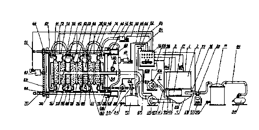
Fig 1. General view of the functionally interconnected belt filter and elastic
thermo-filter press.
Fig. 2 General view of the belt filter.
Fig. 3 Diagram of the vertical cross-section of the filter sector.
Fig. 4 Diagram of the horizontal cross-section of the filter sector.
Fig. 5 Diagram of the transverse cross-section of the continuous drain belt.
Fig. 6. View of the internal side of the continuous drain belt.
Fig. 7. Diagram of the transverse cross-section of the elastic thermo-filter
press after closing the elastic thermo-filter press by the self-propelled
head.
CA 02274683 1999-06-10
WO 98/25684 PCTBG97100012
9
Fig. 8 Diagram of the transverse cross-section of the elastic thermo-filter
press after longitudinal shrinkage of the elastic thermo-filter press by the
action of
the hydraulic cylinders.
Fig. 9 Diagram of the elastic filter plates.
Fig. 10. Vertical cross-section of the elastic filter plates.
Fig.l1. General view of the elastic thermo-filter press in open position.
DETAILED DESCRIPTION OF THE PREFERRED EMBODIMENTS
The apparatus for continuous purification of liquids, dewatering and drying
of the separated non-filtering solids includes a belt filter 1 and an elastic
thermo-
filter press 35.
The belt filter 1 (Fig. 1 and 2) consists of a feed container 2, filter sector
3
and thickening cone 9.
The filter sector 3 (Fig. 1 - 4) is located under the feed container 2, and
the
thickening cone 9 is connected in its upper portion to filter sector 3. The
bottom
part of the thickening cone 9 (Fig. 1) is connected by a fixing unloading pipe
10,
pipe 11, a combined vacuum-pressure pump 12 and a feed pipe 67, to the elastic
thermo-filter press 35.
The filter sector 3 (Fig. 1 - 4) is connected by an outlet vacuum pipe 18, a
vacuum collector 19 and a main vacuum pipe 60 to a main vacuum pump 59. The
filter sector 3 is connected at its other side by a reducing pipe 28, a
pressure pipe
107, a second combined vacuum-pressure pump 104, a second vacuum
collector 72 and a thermo-fluid detector 50 to the elastic thermo-filter press
35.
The filter sector 3 (Fig. 1 - 4) consists of a robust frame 4 which houses a
perforated absorption chamber 5, an elastic box 88 and a perforated drive drum
22. To the perforated absorption chamber 5 are mounted a gas inpenetrable
sheathing 14 and a porous chamber partition 13.. A basket 15 filled with
absorbent 16 is located in the perforated absorption chamber 5. A sealed cover
17 is connected to the perforated absorption chamber 5.
A vacuum chamber 6 (Fig. 3 and 4) is shaped by the porous chamber
partition 13 and the gas inpenetrable sheathing 14. The vacuum chamber 6 is
CA 02274683 1999-06-10
WO 98/Z5684 PCT/BG97/00012
'! 0
connected through the outlet vacuum pipe 18, the vacuum collector 19 and the
main vacuum pipe 60 to the main vacuum pump 59.
A continuous drain belt 7(Fig. 3 = 6) is laid on 'spacing rollers 34 upon the
perforated absorption chamber 5 and the gas impenetrable sheathing 14.
A belt screen 21 (Fig. 3 and 4) is located above the gas impenetrable
sheathing 14) and is linked to the one side of the elastic box 88. The
perforated
drive drum 22 is located at the opposite side of the elastic box 88.
The perforated drive drum 22 (Fig. 3 and 4) is connected to a second
motor reducing gear 80. The perforated drive drum 22 is linked to the fixed
hollow shaft 27 through second sealed bearings 102, and through sealed
bearings 30 the perforated drive drum 22 is linked to the robust frai~ne 4.
A fixed screen 24 (Fig. 3 and 4) with a horizontal screen slit 25 is mounted
cc,ncentrically into the interior of the perforated drive drum 22. The fixed
hollow
shaft 27 is linked in sequence by its one side through the reducing pipe 28,
the
pressure pipe 1.07, the second combined vacuum pressure pump 104, the
second vacuum collector 72 and the thermo-fluid detector 50 to the elastic
thermo-filter press 35. The fixed hollow shaft 27 is blind in its second end
and is
fixed by a second fixed connection 101 to the robust frame 4.
The elastic box 88 (Fig. 3 and 4) consists of a frame 90, a solid sliding arch
89 and two semi-free sliding arches 91 mounted one upon the other and
suspended elastically by their opposite sides to the elastic box 88. A jack 94
is
mounted between the frame 90 and under the semi-free sliding arches 91. A
supporting component 93 is mounted under the semi-free sliding arches 91, and
the supporting component 93 is linked to the upper part of the jack 94.
The continuous filter belt 8 (Fig. 3, 4) embraces in succession the
continuous drain belt 7, the belt screen 21, the elastic box 88 and the
perforated
drive drum 22. Magnetic filaments 97 are interwoven in the continuous filter
belt 8.
Rollers 79 second rollers 92 and cleaners 23 are located upon the external
surface of the continuous filter belt 8. A magnetic detector 98 is fixed to
the
robust frame 4.
A control panel 56 (Fig. 1 and 7) is connected to the combined vacuum
pressure pump 12, to the second combined vacuum pressure pump 104, to the
_. .r. T __
CA 02274683 1999-06-10
WO 98/25684 PCTBG97/00012
11
jack 94, to the magnetic detector 98, to the second motor reducing gear 80) to
the air filter 112 which is connected to the second vacuum collector 72 and to
a
density detector 95,mounted in the thickening cone 9:
The elastic thermo-filter press 35 (Fig. 1, 7, 8, 11) consists of elastic
filter
plates 40,aligned in sequence between heating plates 38 following each one
after
another. Elastic hollow conduits 75 are laid on both sides of internal frames
39 of
the elastic filter plates 40. Heating membranes 73 with teed inlets 113a are
mounted into the heating plates 38. A self-propelled head 36 is couples by
guide
nuts 66 to guide screws 70 located at the one end of robust stems 46 and at
their
other end the robust stems 48 are connected to pistons 116, lying in hydraulic
cylinders 45. The hydraulic cylinders 45 are fixed to fixed head 37 'and
hydraulic
pipes 68 are linking the hydraulic cylinders 45 to a hydraulic pump 43. The
fixed
head 37 is connected by fixed couplings 87 to supporting beams 85. Tire self-
propelled head 36, the elastic filter plates 40, the thermo plates 38 and the
fixed
head 37 are interconnected by pivots 44. The elastic filter plates 40 are
interconnected by flexible pipes 42. The flexible pipes 42 are connected to
fluid
pump 47. The elastic filter plates 40 are interconnected at their lower parts
by
flexible vacuum pipes 78. The flexible vacuum pipes are connected through the
thermo-fluid detector 50, the second vacuum collector 72 to the second
combined vacuum pressure pump 104.
The elastic filter plate 40 (Fig. 1, 7, 8, 9, 11,) comprises an internal frame
39,
and in the lower part of the internal frame 39 is located a vacuum duct 710.
The
vacuum duct 110 is connected in its external end to flexible vacuum pipes 78
and
in its internal end it is connected to vacuum filter chamber 64 of the filter
plate 40.
The vacuum filter chamber 64 is limited by the internal frame 39 and two
parallel
porous partitions 74. A tube feed inlet 113 is located in the vacuum filter
chamber
64 and in the porous partitions 74. The tube feed inlet 113 is connected to
the
combined vacuum pressure pump 12 by a feed pipe 67.
A fluid canal 76 is located in the internal frame 39. The fluid canal 76 is
connected at its external end with flexible pipes 42, and the internal end of
the
fluid canal 76 is connected to the elastic hollow conduits 75. The internal
frame
39 is embraced by elastic frame 41.
CA 02274683 1999-06-10
WO 98/25684 PCTBG97100012
12
The elastic hollow conduits 75 are formed between the internal frame 39
and the elastic frame 41. The elastic hollow conduits 75 are located at the
two
parallel and vertical sides of the internal frame 39. The control panel 56 is
connected to a motor reduction gear 65, to the heating membranes 73, to the
fluid pump 47, to the hydraulic pump 43, to the thermo-fluid detector 50 and
to a
control valve 53.
MANNER OF OPERATION
The apparatus of the invention operates as follows:
The liquid to be purified 62 comprising basically industrial and household
waste liquids, or water from natural water sources, is permanently fed into a
feed
container 2 of a belt filter 1 whilst the liquid is maintairied at a constant
level.
By action of hydrostatic pressure and vacuum, the liquid to be purified 62
is filtered through a continuous filter belt 8 and through a continuous drain
belt 7
flows in a perforated absorption chamber 5.
In the perforated absorption chamber 5 a basket 15 is located, filled by
absorbing substance 16, selectively catching any detrimental ion components.
The liquid to be purified 62, after passing through the countinuous filter
belt
8, the continuous drain belt 7 and the absorbing substance 16, flows out as
purified liquid 61.
Then, by the action of hydrostatic pressure and vacuum from a main
vacuum pump 59, the purified liquid 61 is passed through a porous chamber
partition 13 into a vacuum chamber 6 and through an outlet vacuum pipe 18 is
then fed into a vacuum collector 19.
An ozonizer 57 with ozonizing nozzle 20 is mounted to the outlet vacuum
pipe 18 and ensures additional bacterial sterility. Thus the purified liquid
61 is
accumulated in the lower portion of a vacuum collector 19 and is regularly
removed through the purified liquid valve 58.
Vacuum in the vacuum collector 19 is maintained by the main vacuum
pump 59 through a main vacuum pipe 60.
_.._. _. T T ._ .~.~_.
CA 02274683 1999-06-10
= WO 98/25684 PCT/BG97/00012
13
When the absorbing substance 16 becomes saturated with detrimental ion
components, a sealed cover 17 opens, and the absorbing substance 16 is
replaced by a fresh portion.
The continuous filter belt 8 is driven by a perforated drive drum 22.
The continuous filter belt 8 is sliding upon the surfaces of a solid sliding
arch 89 and half-free sliding arches 91 forming together a flexible box 88,
and
upon the surface of a belt screen 21. The continuous filter belt 8 drives a
continuous drain belt 7 adhering tightly to its surface.
The continuous drain belt 7 is rotated upon the perforated absorption
chamber 5 and a gas impenetrable sheathing 14 by means of spacer rolls 34,
mounted under the lamellae 31 of the continuous drain belt 7.
The filtered liquid is drained through canals 32 of laminae 31 and flows out
through spacer joints of the lamellae 31 formed by pivot connections 33, and
the
filtered liquid flows into the perforated absorption chamber 5.
Non-filtering solids 103 stick to the outer surface of the continuous filter
belt
8 only at its portion where the continuous filter belt 8 gets into contact
with the
surface of the continuous drain belt 7.
Cleaners 23 are permanently separating the non-filtering solids 103 from
the surface of the continuous filter belt 8 at the line where the continuous
filter belt
8 is detached from the continuous drain belt 7, and at the line where the
continuous filter belt 8 gets into contact with the surface of the perforated
drive
drum 22.
In filter sector 3, rollers 79 and secondary rollers 92 press the continuous
filter belt 7 to the belt screen 21 and to the flexible box 88.
To the filter sector 3, horizontal supporting components 100 are mounted
which are fixed to a robust frame 4 and support the perforated absorption
chamber 5, the vacuum chamber 6, and the flexible box 88, thus ensuring their
stability in the process of operation.
The half-free sliding arches 91 of the flexible box 88 are permanently
straining the continuous filter belt 8 by means of a supporting segment 93,
which
supporting segment 93 is pressing the half-free sliding arches 91 by the
action of
CA 02274683 1999-06-10
WO 98125684 PCTBG97/00012
14
a jack 94, mounted on a frame 90 of the flexible box 88 and the bottom part of
the
flexible box 88 is a solid arch 89.
A hydraulic jack connection 115 is linked to a control panel 56 and
maintains the necessary tension of the continuous filter belt 8.
Magnetic fibres 97 are interwoven in the continuous filter belt 8 and are
signaling to a magnetic detector 98 any changes of speed.
Thus) through a signal circuit 99 of the magnetic detector 98, the control
panel 56 controls the speed of the continuous filter belt 8 and regulates it
through
the hydraulic jack connection 115 by eliminating the sliding (friction)
between the
continuous filter belt 8 and the perforated drive drum 22.
The perforated drive drum 22 is rotated by a second motor reductor gear
80 through a second chain 111.
The perforated drive drum 22 is linked through its internal side to a fixed
hollow shaft 27 by secondary sealed bearings 102, and through its external
side it
is connected to the robust frame 4 by sealed bearings 30.
The second motor reductor gear 80 is power supplied and controlled by a
cable line 114 of the control panel 56.
In the middle of the fixed hollow shaft 27 a nozzle 29 is located.
Through the nozzle 29, filtrate 71 or aerosol 26 are fed under pressure.
One end of the fixed hollow shaft 27 is blind and is fixed by means of a
second fixed coupling 101 to the robust frame 4.
A fixed screen 24 screens the inside of the perforated drive drum 22 and is
attached to the fixed hollow shaft 27.
A horizontal screen slit 25 of the fixed screen 24 gives shape to a wide and
thin pressure jet of the filtrate 71 or the aerosol 26, cleaning the
micropores of the
continuous filter belt 8 from the non-filtering solids 103.
Thus the filtering capacity of the continuous filter belt 8 is practically
preserved for a long period of operation.
It is clear from the aforesaid that the liquid to be filtered 62 is
permanently
fed into the feed container 2 of belt filter 1, and the purified liquid 61 is
permanently separated from vacuum chamber 6.
_ _ _ ~___. ___ _. _ ~_T.__. _
CA 02274683 1999-06-10
WO 98/25684 PCT/BG97/00012
The non-filtering solids 103 collected upon the continuous filter belt 8 are
mixed with the fed liquid to be purified 62 and the mixture (slurry) thus
obtained is
continuously thickened.
The increasing thickness is permanently controlled by a density detector
95 connected through a second signal line 96 to the control panel 56.
When the desired density is reached, an elastic thermo-filter press 35 is
included in the dewatering and drying process of the thickened mixture
(slurry) in
the belt filter 1 only when the control panel 56 activates a fluid pump 47
through a
first operating line 48.
Through flexible pipes 42 and fluid ducts 76 the fluid pump 47 compresses
fluid into elastic hollow conduits 75 formed by elastic frames 41 and internal
frames 39 of elastic filter plates 40.
The elastic hollow conduits 75 are located on the two parallel sides of the
internal frame 39,
Robust rims 69 embrace the external portions of the elastic filter plates 40.
The flexible hollow conduits 75 expand to a predetermined size under the
impact of fluid pump 47.
When the predetermined size and pressure are reached, the control panel
56 stops the fluid pump 47 and activates, through a third operating line 83 a
motor redactor gear 65, and by means of chain 108 and drive nuts 66 moves a
self-propelled head 36 along guide screws 70 formed at the one end of robust
stems 46.
The motor-redactor gear 65 is switched off automatically whenever the
self-propelled head 36 closes the elastic thermo-filter press 35.
The expanded hollow conduits 75 ensure a tight and reliable contact
between the flexible filter plates 40 and heating plates 38.
The expanded hollow conduits 75 expand the chambers limited by the
flexible filter plates 40 and the heating plates 38. In the expanded chambers,
the
volume of accumulated cake 63 is increased.
Whenever the elastic thermo-filter press 35 is closed, the control panel 56
activates a combined vacuum and pressure pump 12 through a fourth operating
line 84.
CA 02274683 1999-06-10
WO 98/25684 PCT/BG97/00012
16
The combined vacuum and pressure pump 12 draws out the thickened
mixture (slurry) from the bottom of a thickening cone 9 through a fixing
unloading
pipe 10 and a pipe 11.
The thickened mixture (slurry) is then compressed through a feed pipe 67
and a tube feed inlet 113 into the chambers limited by the elastic filter
plates 40
and the heating plates 38.
The filtrate 71 is separated by porous partitions 74 under the pressure
produced by the combined vacuum and pressure pump 12 and the vacuum
developed in vacuum filter chambers 64 by a second combined vacuum
pressure pump 104 linked through a fifth operating line 105 to the control
pane!
56.
From the vacuum filter chambers 64, the filtrate 71 flows through vacuum
ducts 110, vacuum flexible pipes 78 and a thermo-fluid detector 50 into a
second
vacuum collector 72.
The filtrate 71 can be regularly let out by a filtrate valve 54.
The filtrate 71 can also be pumped out by the second combined vacuum
pressure pump 104 through a second feed pipe 106 and through a pressure pipe
107, a reducing pipe 28, the fixed hollow shaft 27, and the nozzle 29, to be
fed
into the perforated drive drum 22.
The filtration process is controlled by the thermo-fluid detector 50) and
through a thermo-fluid detector connection 82 the filtration processed is
recorded by the control panel 56.
After the completion of the filtration process, the control panel 56 activates
a hydraulic pump 43 through a second operating line 49.
The hydraulic pump 43 activates hydraulic cylinders 45 through hydraulic
pipes 68.
The activation of the hydraulic pump 43 makes the control panel 56 set into
operation heating membranes 73 of the heating plates 38 through a power
supply cable 51.
Around the surface of the heating membranes 73 a process of evaporation
of the residual liquid phase begins, leading to the formation of a "steam
jacket".
.~...___. ._ __..___ _-~__T..__._.._....-
CA 02274683 1999-06-10
WO 98/25684 PCTBG97/00012
17
Simultaneously with the activation of the hydraulic pump 43, the control
panel 56 starts the switched-off the fluid pump 47 through the first operating
line
48, and at this stage the fluid pump 47 lowers the pressure in the flexible
pipes 42
which results in a gradual shrinking of the elastic hollow conduits 75.
The hydraulic cylinders 45 mounted on a fixed head 37 pull out, under the
effect of the pressure of the hydraulic pump 43, pistons 116 of the hydraulic
cylinders 45. The pistons 116 are connected to the second ends of the robust
stems 46.
Thus the distance between the self-propelled head 36 and the fixed head
37 is decreased, i.e. the elastic thermo-filter press 35 contracts
longitudinally.
As a result of the contraction under the effect of the hydraulic cylinders 45,
the volume of the cake 63 accumulated in the chambers limited by the elastic
filter plates 40 and the heating plates 38 begins to compress and shrink.
Thus the second stage of dewatering begins, accompanied by partial
evaporation.
During the second stage, the residual liquid phase in the capillaries of the
cake 63 is filtered through the porous partitions 74 into the vacuum-filter
chambers 64 under the simultaneous effect of:
- the vapours of the "steam jacket" formed on the surface of the heating
membranes 73 which push out the capillary liquid phase;
- the mechanical pressing and squeezing of the cake 63 under the impact
of the hydraulic cylinders 45; and
- the vacuum developed by the second combined vacuum pressure pump
104.
The residual liquid phase entering by filtration into the vacuum filter
chambers 64, is practically the aerosol 26 comprising: liquid, steam and air.
The aerosol 26 flows further through the thermo-filter detector 50, the
second vacuum collector 72, the second feed pipe 106, the second combined
vacuum and pressure pump 104, the pressure pipe 107, the reducing pipe 28,
the fixed hollow shaft 27, the nozzle 29, the horizontal screen slit 25; and
through
the perforated drive drum 22 the aerosol 26 cleans the micropores of the
CA 02274683 1999-06-10
WO 98/25684 PCT/BG97/00012
18
continuous fitter belt 8 and then the aerosol 26 is mixed with the liquid fed
to be
purified 62 in the belt filter 1.
Thus, the thermal energy accumulated in the aerosol 26, imparted by the
heating membranes 73 of the heating plates 38, is conveyed with negligible
losses to the liquid fed to be purified 62.
The second stage of dewatering is completed with the end of aerosol
separation, i.e. the cake 63 is dewatered and dried to a maximum.
Separation of the aerosol 26 is controlled by the thermo-fluid detector 50,
and the signal obtained is fed to the control panel 56 through the thermo-
fluid
detector connection 82.
At the end of the second stage, the control panel 56 issues a signal for:
- the switching off of the hydraulic pump 43;
- the switching off of power supply cable 51 to the heating membranes 73 ;
- the switching on of the self-propelled head 36, which opens the elastic
thermo-filter press 35, and thus increases the distance between the elastic
filter
plates 40 and the heating plates 38 interconnected by pivots 44;
- the switching on of vibrating stems 109 located in the supporting columns
86.
The vibrations of the vibrating stems 109 are imparted through supporting
beams 85 and the supporting rolls 77, to the elastic filter plates 40 and the
heating plates 38 suspended on the supporting beams 85.
In result of the effect of vibrations, the dewatered and dried cake 63 is
disconnected from the heating plates 38 and the elastic filter plates 40, and
falls
into an appropriate hopper.
The fixed head 37 is connected by a fixed coupling 87 to the supporting
beams 85.
A manometer 81 indicates the pressure in the chambers of the elastic
thermo-filter press 35.
The thickening cone 9 can be cleaned regularly by removing a thickening
cover 55.
The belt filter 1 can be equipped with two or more filter sectors 3.
~ .._._ ~._._.. __. T ~.. . .._.._.~.__ _
CA 02274683 1999-06-10
WO 98/25684 PCTBG97/00012
19
After the discharge of the cake 63, the elastic thermo-filter press 35 is
ready for the next working cycle. The start of the next working cycle is
determined by the moment when the density of the resulting mixture of non-
filtering solids 103 and the liquid to be purified 62 flowing into the belt
filter 1,
reaches a predetermined value.
The time interval from the end of one cycle until the beginning of the
following cycle varies within a wide scope depending on the characteristics
and
volume of the liquid to be purified 62.
When the elastic thermo-filter press 35 is engaged and operates only with
the belt filter 1, its production capacity may remain to a great extent
unused.
In such cases, it is economically efficient to link one elastic thermo-filter
press 35 with two or more belt filters 1 in the process of operation, or to
build in
two or more filter sectors 3 in one belt filter 1.
The belt filter 1 and the elastic thermo-filter press 35 can function
separately as two apparatuses independent from each other.
When the belt filter 1 operates independently, a control valve 53 connected
to the control panel 56 through a control line 52 switches off the thermo-
fluid
detector 50 and switches the air filter 112.
In this case, the second combined vacuum and pressure pump 104;
compresses air into the perforated drive drum 22, and this air cleans the
micro
pores of the continuous filter belt 8.
The thickened mixture of non-filtering solids 103 and the inflowing liquid to
be purified 62 is brought out by the thickening cone 9 by the action of the
combined vacuum and pressure pump 12 after reaching the predetermined value
of density (thickening).
The elastic thermo-filter press 35 can operate independently by being
supplied from various sources with mixtures of liquids containing dispersed
solids (slurry mass).
The supply to the elastic thermo-filter press 35 is performed by the
combined vacuum and pressure pump 12.
The control valve 53 disconnects the air filter 112.
CA 02274683 1999-06-10
WO 98/25684 PCT/BG97/00012
The filtrate 71, by the action of the second combined vacuum and pressure
pump 104, is collected through the thermo-filter detector 50 into the second
vacuum collector 72.
Although the invention is described and illustrated with reference to a
plurality of embodiments therefore, it is to be expressly understood that it
is in no
way limited to the disclosure of such preferred embodiments, but is capable of
numerous modifications within the scope of the appended claims.
i _T . T