Language selection

Search

Patent 2275070 Summary

Third-party information liability

Some of the information on this Web page has been provided by external sources. The Government of Canada is not responsible for the accuracy, reliability or currency of the information supplied by external sources. Users wishing to rely upon this information should consult directly with the source of the information. Content provided by external sources is not subject to official languages, privacy and accessibility requirements.

Claims and Abstract availability

Any discrepancies in the text and image of the Claims and Abstract are due to differing posting times. Text of the Claims and Abstract are posted:

  • At the time the application is open to public inspection;
  • At the time of issue of the patent (grant).
(12) Patent: (11) CA 2275070
(54) English Title: RAILWAY TRUCK SIDEFRAME WITH REINFORCED COLUMNS
(54) French Title: LONGERON DE BOGIE AVEC COLONNES RENFORCEES POUR WAGONS-MARCHANDISES
Status: Expired and beyond the Period of Reversal
Bibliographic Data
(51) International Patent Classification (IPC):
  • B61F 5/52 (2006.01)
(72) Inventors :
  • HAWTHORNE, TERREY V. (United States of America)
  • MOEHLING, CHARLES (United States of America)
  • TOUSSAINT, BRIAN A. (United States of America)
  • GOLEMBIEWSKI, RONALD D. (United States of America)
(73) Owners :
  • AMSTED INDUSTRIES INCORPORATED
(71) Applicants :
  • AMSTED INDUSTRIES INCORPORATED (United States of America)
(74) Agent: GOWLING WLG (CANADA) LLP
(74) Associate agent:
(45) Issued: 2002-06-11
(22) Filed Date: 1999-06-17
(41) Open to Public Inspection: 1999-12-26
Examination requested: 1999-06-17
Availability of licence: N/A
Dedicated to the Public: N/A
(25) Language of filing: English

Patent Cooperation Treaty (PCT): No

(30) Application Priority Data:
Application No. Country/Territory Date
09/105,993 (United States of America) 1998-06-26

Abstracts

English Abstract


The present invention provides a sideframe for use in a traditional three
piece railway
freight car truck comprising a pair of laterally spaced sideframes supporting
a bolster
extending between the sideframes. Each sideframe comprises an elongated top
compression
member, two diagonal compression members extending generally downwardly at
acute angles
from near the ends of the top compression member, and a bottom member joining
the other
ends of the diagonal tension members. Two column members also extend
vertically between
the bottom member and the top compression member. Such column members are
strengthened
by two ribs that extend laterally across the structure of the column member
between sidewalls
of the column member.


Claims

Note: Claims are shown in the official language in which they were submitted.

WHAT IS CLAIMED IS:
1. A sideframe for use is a railway car truck,
said sideframe of a generally unitary cast steel structure comprising an
elongated
top compression member extending longitudinally,
two end sections each extending longitudinally from an end of said top
compression member and each forming a pedestal jaw,
two diagonal tension members each extending at an acute angle with said top
compression member from near said end of said top compression member,
a bottom member extending longitudinally and joining said diagonal tension
members at a lower end of each diagonal tension member,
two column members longitudinally spaced from each other and extending
vertically between said bottom member and said top compression member,
said column members forming a bolster opening therebetween,
each of said column members having a closed structural cross section comprised
of a main section extending laterally across the width of said column member,
two wear plate support sections each protruding longitudinally inwardly toward
said bolster
opening from a lateral end of said main section, and two sidewalk each
protruding longitudinally
outwardly from a lateral end of said main section, each of said sidewalk
extending vertically for
nearly the entire height of said column member,
and a first support rib comprising a generally planar section extending
laterally
outwardly from said main section and from adjoining sections of said two
sidewalk of said
column member,
-8-

a second support rib comprising a generally planar section extending laterally
outwardly from said main section and from adjoining sections of said two
sidewalk of said
column member, said second support rib spaced vertically below said first
support rib,
two vertically aligned wear plate bolt openings in said main section of said
column member,
with said first support rib vertically aligned approximately between said wear
plate bolt openings,
and a generally rectangular, generally flat wear plate held against said main
section of said column member by bolts that extend through said wear plate
bolt openings,
and wherein said second support rib is vertically aligned with a bottom edge
of
said wear plate.
2. The sideframe of claim 1
wherein said first support rib extends about 1.0 inch from said main section
of
said column member, and wherein said first support rib includes an inside edge
that extends from
each of said sidewalk at an acute angle and extends through arucate sections
to form a lateral
mid-section generally parallel to said main section of said column member.
3. The sideframe of claim 1
wherein said second support rib extends about 1.5 inches from said main
section
of said column member, and wherein said second support rib includes an inside
edge that extends
from each of said sidewalk at an acute angle and extends through arcuate
sections to form a
lateral mid-section generally parallel to said main section of said column
member.
-9-

4. A sideframe for use in a railway car truck,
said sideframe of a generally unitary cast steel structure comprising
an elongated top compression member,
two diagonal tension members each extending generally downwardly at an acute
angle from near an end of said top compression member,
a bottom member joining said diagonal tension members at a lower end of each
diagonal tension members at a lower end of each diagonal tension member,
two column members extending generally vertically between said bottom member
and said top compression member,
said column members forming a bolster opening therebetween,
each of said column members having a generally closed structural cross
section,
comprising a main section extending laterally, and two sidewalk extending
generally
perpendicular to and outwardly from said main section,
an upper support rib comprising a generally planar structure extending
outwardly
from said main section of said column member and from adjoining sections of
said two sidewalk
of said column member,
a lower support rib comprising a generally planar structure extending
outwardly
from said main section of said column member and from adjoining sections of
said two sidewalk
of said column member, said lower support rib spaced vertically below said
upper support rib,
two vertically aligned wear plate bolt openings in said main section of said
column member,
with said upper support rib vertically aligned approximately between said war
plate bolt openings,
-10-

and a generally rectangular, generally flat wear plate held against said main
section of said column member by bolts that extend through said wear plate
bolt openings,
and wherein said lower support rib is vertically aligned with a bottom edge of
said
wear plate.
5. The sideframe of claim 4
wherein said upper support rib extends about 1.0 inch from said main section
of
said column member, and wherein said upper support rib includes an inside edge
that extends
from each of said sidewalk at an acute angle and extends through arcuate
sections to form a
lateral mid-section generally parallel to said main section of said column
member.
6. The sideframe of claim 4
wherein said lower support rib extends about 1.5 inches from said main section
of said column member, and wherein said lower support of said column member,
and wherein
said lower support rib includes an inside edge that extends from each of said
sidewalk at an acute
angle and extends through arcuate sections to form a lateral mid-section
generally parallel to said
main section of said column member.
-11-

Description

Note: Descriptions are shown in the official language in which they were submitted.


CA 02275070 1999-06-17
6181-Hawthorne et al.
RAILWAY TRUCK SIDEFRAME WITH REINFORCED COLUMNS
BACKGROUND OF THE INVENTION
The present invention relates to railway freight car trucks and, more
particularly, to
railway freight car truck sideframes having an improved and strengthened
column member.
Railway freight car trucks are usually comprised of a three piece arrangement
wherein
each truck includes two sideframes laterally spaced from each other. Each
sideframe includes a
centrally located opening formed by vertical columns. Such centrally located
opening is usually
referred to as the bolster opening or pocket and is adapted to receive the
ends of a bolster
extending laterally from and perpendicular to the sideframes. The ends of each
sideframe are
laterally aligned to receive an axle wheel set in what is usually termed the
pedestal jaw of the
sideframe.
Typical three piece railway freight car trucks are shown in U.S. Patent Nos.
4,363,276;
4,838,174; and 5,718,177.
A typical railway freight car truck sideframe is comprised of an elongated top
compression member that extends in a longitudinal direction parallel to the
railway track. The
sideframe also comprises two diagonally extending tension members that extend
generally
downwardly at an acute angle from near the ends of the top compression member.
A bottom
member extends longitudinally and joins the lower ends of the diagonal tension
members.
Column members extend generally vertically between the bottom member and the
top
compression member from a point near the junction of the diagonal tension
members and the
bottom member. Such column members form the bolster opening in the sideframe.
A top
portion of the bottom member of a sideframe is usually referred to as the
spring seat of the

CA 02275070 1999-06-17
sideframe as it is adapted to receive the spring group upon which the ends of
the bolster are
supported. The bolster extends laterally between each sideframe with the ends
of the bolster
extending into the bolster pockets and supported on a spring group.
It should be understood that the sideframe is an engineered structural member
that is
largely hollow to accomplish weight saving. It should also be understood that
the sideframe is a
unitary cast steel structure made in a foundry casting operation. Accordingly,
it is possible to
strengthen the sideframe by the addition of various supporting structures that
would become part
of the unitary sideframe. However, such addition of strengthening members is
always balanced
against the need for lighter weight freight car trucks.
From time to time, certain freight car truck designs exhibit various degrees
of decreased
performance when exposed to higher capacity service. For example, certain
variable damped
railway freight car trucks experienced cracking in their sideframe columns
when utilized in 125
ton freight car service. Such freight car truck sideframes utilized in general
the column support
shown in U.S. Patent No. 4,363,276 wherein a single horizontal support rib
provides lateral
support for the columns.
Accordingly, it is an object of the present invention to provide an improved
and
strengthened railway truck sideframe.
It is another object of the present invention to provide a railway truck
sideframe having an
improved and strengthened column structure thereby particularly providing an
improved and
strengthened bolster pocket.
-2-

CA 02275070 1999-06-17
SUNiNIARY OF THE INVENTION
The present invention provides an improved and strengthened column member of a
railway truck sideframe. Each sideframe of a railway freight car truck is
formed of a unitary
cast steel structure. Each sideframe includes an elongated top compression
member that
extends longitudinally and parallel to the railway tracks. Two end sections
each extend
longitudinally from each end of the top compression member and form pedestal
jaws adapted
to receive the axle bearing end of the wheel sets. Two diagonal tension
members extend
generally downwardly from near the end of the top compression member at an
acute angle to
the top compression member. A bottom member extends longitudinally and joins
the lower
ends of the diagonal members. Two column members are longitudinally spaced
from each
other and extend vertically between the bottom member and top compression
member. The
column members form the bolster opening or pocket of each sideframe. The top
surface of the
bottom member is referred to as the spring seat and is adapted to receive the
spring group
upon which the end of the bolster is supported.
Each column is a generally structural member having a cross section comprised
of the
main section extending laterally across the width of the column member. Two
wearplate
support sections protrude longitudinally inwardly toward the bolster opening
from lateral ends
of the main section of the column member. Two sidewalls protrude
longitudinally outwardly
away from the bolster opening from lateral ends of the main section of the
column member.
A first support rib is provided having a generally planar section extending
laterally
outwardly from the main section of the sideframe column and from joining
sections of the two
sidewalls. Such first support rib is usually vertically aligned approximately
between wearplate
-3-

CA 02275070 1999-06-17
bolt openings in the sideframe column. A second support rib is comprised of a
generally
planar section extending laterally outwardly from the main section of the
sideframe column
and from adjoining sections of the two sidewalls of the column member. The
second support
rib is spaced vertically below the first support rib, usually in alignment
with the bottom of the
column wearplate.
BRIEF DESCRIPTION OF THE DRAWINGS
In the drawings:
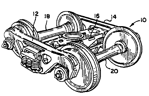
Figure 1 is a perspective view of a railway truck comprised of two sideframes
and a
bolster;
Figure 2 is a side view of a sideframe in accordance with the present
invention;
Figure 3 is a partial side view of a sideframe in accordance with the present
invention;
Figure 4 is a cross sectional view of a sideframe in accordance with the
present
invention along lines 4-4 of Figure 3;
Figure 5 is a partial cross sectional view of a portion of a sideframe column
in
accordance with the present invention along lines 5-5 of Figure 3; and
Figure 6 is a partial cross sectional view of another portion of a sideframe
column in
accordance with the present invention along lines 6-6 of Figure 3.
DETAILED DESCRIPTION OF THE INVENTION
Referring now to Figures 1 and 2 of the drawings, a railway truck in
accordance with
the present invention is shown generally at 10. Railway truck 10 comprises
sideframes 12 and
-4-

CA 02275070 1999-06-17
14 that are identical and are laterally spaced from each other. Axle wheel
sets 18 and 20 are
received in pedestal openings 27 and 29 formed at respective end sections 26
and 28 of each
sideframe. Bolster 16 extends laterally between sideframes 12 and 14 and is
received in
bolster openings intermediate the pedestal ends of both sideframes. Bolster
opening 40 is
shown in Figure 2 for sideframe 12.
Referring now to Figure 2 of the drawings, sideframe 12 is comprised of a
longitudinal
elongated top compression member 24 that runs longitudinally across the top
part of sideframe
23 and ends in end sections 26 and 28. It is seen that pedestal opening 27 is
formed at a lower
portion of end section 26 and pedestal opening 29 is formed at a lower portion
of section 28.
Diagonal tension members 30 and 32 extend downwardly from top compression
member 24 at
a point near end sections 26 and 28. The angle at which diagonal tension
members 30 and 32
extend is about 45 degrees. Bottom section 34 extends longitudinally and joins
the lower end
sections of diagonal tension members 30 and 32. Column members 36 and 38 are
spaced
longitudinally from each other and extend vertically from an upper portion of
bottom section
34 near its junction with diagonal tension members 30 and 32 to a lower
surface of top
compression member 24. It is seen that the combination of the lower portion of
top
compression member 24, the upper portion of bottom section 34 and column
members 36 and
48 form a generally rectangular bolster opening 40. The upper surface of
bottom section 34 is
also referred to as spring seat 42.
It should be understood that sideframes 12 and 14 are unitary cast steel
structures.
Such structures are cast in accordance with modern foundry practice that
includes the use of
cores to form the structural components of sideframe 12 in a generally hollow
fashion such
-S-

CA 02275070 1999-06-17
that each structural component such as top compression member 24 and bottom
section 34 are
generally hollow, each comprised of a bottom section and a top section and two
side sections
joined to the top and bottom sections.
Referring now to Figure 4 of the drawings, a cross sectional view of sideframe
12 is
provided along lines 4-4 from Figure 3. Compression member 24 is seen located
above
bottom member 34 and spring seat 42. Top compression member 24 is seen to have
a
generally rectangular cross sectional structure as is bottom member 34. Spring
seat 32 is seen
to have certain raised locating structures for positioning springs upon which
the end of bolster
16 rests. Wearplate 44 is a generally rectangular flat structure that is
affixed to sideframe
column 36 by bolts passing through bolt hole 52 and 54 in sideframe column 36.
Wearplate
34 is adapted to abut a flat vertical surface of a friction shoe damping
device that acts to
dampen the oscillation of bolster 16 supported on the spring group of railway
truck 10.
Referring now to Figure 5 of the drawings, taken along line S-5 of Figure 3,
upper
support rib 46 is shown as extending longitudinally outwardly from main
section 60 of column
36. Wearplate support sections 62 and 64 extend longitudinally inwardly toward
bolster
opening 40 from lateral ends of main section 60 of column 36. Sidewalls 66 and
68 protrude
longitudinally outwardly away from bolster opening 40 from lateral ends of
main section 60 of
column 36. Extending laterally between sidewalls 66 and 68 is upper support
rib 46. Upper
support rib 46 is a unitary cast portion of sideframe 36. Upper support rib 46
is a generally
flat structure having a mid-section 70 and radiused end sections 72 and 74
that extend to and
join the protruding sections of sidewalk 66 and 68. Upper support rib 46 is
located vertically
generally between the sideframe column bolt holes 52 and 54.
-6-

CA 02275070 1999-06-17
Referring now to Figure 6 of the drawings, taken along line 6-6 of Figure 3, a
lower
cross sectional view of sideframe column 36 is shown below the cross sectional
view of Figure
5. Such cross sectional view of column 36 shows a similar structure to that of
Figure 5, with
similar wearplate support sections 82 and 84 extending longitudinally inwardly
toward bolster
opening 40 from lateral ends of main section 61 of sideframe column 36.
Further, sidewalls
86 and 88 protrude longitudinally outwardly away from the bolster opening 40
from lateral
ends of main section 61 of sideframe column 36. Lower support rib 48 is part
of the unitary
cast structure of sideframe column 36. Lower support rib 48 is comprised of a
generally flat
structure extending between sidewalls 86 and 88. Lower support rib 48 includes
a mid-section
90 and radiused sections 92 and 94 each which extends to an intersection with
sidewall 86 and
88, respectively. It is seen that lower support rib 48 provides additional
support for sideframe
column 36. This is especially necessary with the increased load carrying of
today's freight car
trucks wherein the bolster vertical oscillations are damped by the frictional
contact of a friction
shoe whose vertical face contacts wearplate 44 on sideframe column 36.
It is further understood that similar support ribs are a part of sideframe
column 38 but
for reasons of brevity they are not described in detail herein.

Representative Drawing
A single figure which represents the drawing illustrating the invention.
Administrative Status

2024-08-01:As part of the Next Generation Patents (NGP) transition, the Canadian Patents Database (CPD) now contains a more detailed Event History, which replicates the Event Log of our new back-office solution.

Please note that "Inactive:" events refers to events no longer in use in our new back-office solution.

For a clearer understanding of the status of the application/patent presented on this page, the site Disclaimer , as well as the definitions for Patent , Event History , Maintenance Fee  and Payment History  should be consulted.

Event History

Description Date
Appointment of Agent Requirements Determined Compliant 2010-06-23
Revocation of Agent Requirements Determined Compliant 2010-06-23
Inactive: Office letter 2010-06-22
Time Limit for Reversal Expired 2010-06-17
Revocation of Agent Request 2010-06-10
Appointment of Agent Request 2010-06-10
Letter Sent 2009-06-17
Letter Sent 2007-07-19
Inactive: Correspondence - Transfer 2007-02-22
Grant by Issuance 2002-06-11
Inactive: Cover page published 2002-06-10
Pre-grant 2002-03-27
Inactive: Final fee received 2002-03-27
Letter Sent 2001-10-15
Notice of Allowance is Issued 2001-10-15
Inactive: Approved for allowance (AFA) 2001-10-01
Amendment Received - Voluntary Amendment 2001-07-18
Inactive: S.30(2) Rules - Examiner requisition 2001-03-05
Inactive: Cover page published 1999-12-26
Application Published (Open to Public Inspection) 1999-12-26
Inactive: First IPC assigned 1999-08-17
Inactive: Filing certificate - RFE (English) 1999-07-22
Filing Requirements Determined Compliant 1999-07-22
Letter Sent 1999-07-22
Application Received - Regular National 1999-07-22
Request for Examination Requirements Determined Compliant 1999-06-17
All Requirements for Examination Determined Compliant 1999-06-17

Abandonment History

There is no abandonment history.

Maintenance Fee

The last payment was received on 2002-04-02

Note : If the full payment has not been received on or before the date indicated, a further fee may be required which may be one of the following

  • the reinstatement fee;
  • the late payment fee; or
  • additional fee to reverse deemed expiry.

Please refer to the CIPO Patent Fees web page to see all current fee amounts.

Owners on Record

Note: Records showing the ownership history in alphabetical order.

Current Owners on Record
AMSTED INDUSTRIES INCORPORATED
Past Owners on Record
BRIAN A. TOUSSAINT
CHARLES MOEHLING
RONALD D. GOLEMBIEWSKI
TERREY V. HAWTHORNE
Past Owners that do not appear in the "Owners on Record" listing will appear in other documentation within the application.
Documents

To view selected files, please enter reCAPTCHA code :


To view images, click a link in the Document Description column. To download the documents, select one or more checkboxes in the first column and then click the "Download Selected in PDF format (Zip Archive)" or the "Download Selected as Single PDF" button.

List of published and non-published patent-specific documents on the CPD .

If you have any difficulty accessing content, you can call the Client Service Centre at 1-866-997-1936 or send them an e-mail at CIPO Client Service Centre.


Document
Description 
Date
(yyyy-mm-dd) 
Number of pages   Size of Image (KB) 
Abstract 1999-06-17 1 21
Description 1999-06-17 7 285
Claims 1999-06-17 5 140
Drawings 1999-06-17 3 78
Cover Page 1999-12-14 1 51
Cover Page 2002-05-09 1 57
Claims 2001-07-18 4 131
Representative drawing 2002-05-09 1 25
Representative drawing 1999-12-14 1 20
Courtesy - Certificate of registration (related document(s)) 1999-07-22 1 140
Filing Certificate (English) 1999-07-22 1 175
Reminder of maintenance fee due 2001-02-20 1 112
Commissioner's Notice - Application Found Allowable 2001-10-15 1 166
Maintenance Fee Notice 2009-07-29 1 171
Correspondence 2002-03-27 1 35
Correspondence 2004-06-08 1 29
Correspondence 2010-06-10 8 328
Correspondence 2010-06-22 1 15