Note: Descriptions are shown in the official language in which they were submitted.
CA 02275453 2001-04-03
Background of the Invention
Preferred Embodiment
This invention relates to the application of a foldable tray delivery system
to a variety
of furniture seating products involving the increase in comfort in performing
certain
activities while seated on such furniture through the implementation of an arm
tray
mechanism utilizing hinge and rotation devices to achieve a convenient and
supportive tray surface area. Daily, occasional or infrequent activities
requiring the
use of a tray while in a seated position,'such as meal consumption, using a
laptop, or
as a writing surface are examples of typical usage of the tray delivery
system.
Previous Patents
The adaptation of tray surfaces to make fine furniture more functional is not
a new
pursuit within the furniture industry or by inventors in general. Many patents
exist
that detail varying attempts at combining a useful tray surface to various
types of fine
furniture including medical applications such as wheel chairs.
One such adaptation is detailed in Canadian Patent No. 530,110, which utilize
clamping members to attach a tray to the arm of a chair, sofa or similar piece
of
furniture. The clamping members themselves can be adjusted varying the
distance
between the clamping members in order to accommodate various furniture arm
designs. While such an assembly does provide a suitably stable surface for
object
placement, its usefulness is limited to that of an end table and therefore not
functional
for other uses such as meal consumption or use of laptops etc.
-2-
CA 02275453 2001-04-03
Another patent exhibiting similar characteristics is US Patent No. 5,649,737
which
attaches a tray to the arm of a chair except positioned further forward.
Unlike the
previous patent, this tray assembly design is specific for recreational and or
folding
seating, yet still serves similar functions for supporting items above the
chair's arm
and not over an individuals lap.
A large portion of patents involving the implementation of trays do not focus
on fine
furniture but rather areas involving transportation and related vehicles such
as
airplanes and trains. The functionality of tray surfaces within these
environments is
directed towards maximizing passenger comfort and personal utility while
travelling.
For example, US Patent No. 4,668,010 involve tilting arms that support a tray
for
usage by airplane travelers. US Patent No. 4,372,604 details a rotating table
mechanism that is concealed within the arm of a bench when not in use. This
invention is primarily directed to the rail transportation industry. Its
functionality is
limited as it primarily serves as an armrest or partially extended table.
Features missing from these patents include the full concealment of the tray
when not
in use, and an inherent storage of the tray or table systems. Implementing
concealment features creates difficulties to the design of a tray or table
system. The
objective of concealment lies in the quest to hide any visible signs of the
tray or table
device therefore leaving the design and style of the furniture untouched. One
patent
that partially displays concealment features is US Patent No. 4,834,449 that
places the
entire tray system within the arm cavity. Deployment of this tray system
begins by
pulling forward the arm facings along sliders to a point where a tray is
flipped
-3-
CA 02275453 2001-04-03
upwards, and then supported by a rotating crossbar. This design does not
significantly detract from the aesthetics of the associated furniture while
stored and
provides a functional tray for an individual when deployed. However in the
extended
position, this system requires a greater furniture footprint, which in turn
can impede
traffic flow within the living space. This system requires the individual to
be seated
well forward in order to use the tray effectively. As a limiting factor, this
system
requires the tray to be positioned in front of the furniture as opposed to
covering the
seating area. Seating comfort and usefulness of the tray then becomes
questionable.
A significant design enhancement would permit the individual to be seated
fully
within the furniture while still maintaining a comfortable distance to the
tray surface.
Such a design improvement can be found within US Patent No. 5,050,929 that
conceals the tray system within the arm of a sofa or chair. However, in this
design
the tray is pulled upward out of the arm and then folded over the individual's
leg. At
this point the tray runs along a groove which permits adjustments for forward
and
backward positioning. Additional footprint space is not required and allows an
individual to sit fully within the seating area. Somewhat limiting, this
system restricts
placement within certain arm styles.
After careful analysis of previously patented designs, features such as
concealment
and adjustable tray depth were identified as key features that consumers would
be
attracted towards. The most common theme depicted in all tray delivery devices
is in
their utilization of the associated furniture's arm as the primary agent of
support. The
-4-
CA 02275453 2001-04-03
efforts presented in this submission have resulted in a new design direction
moving
away from these noted restrictions.
Discussion
Improvements On Previous Designs I Patents
The furniture industry has provided many attempts towards making furniture
more
functional. The focus presented in this submission has been on the development
of a
concealed tray delivery system for various pieces of fine furniture. As
previously
noted, a key theme has been on placing a tray system on, or within, the
associated
furniture's arm. This always involves modification to the arm's structure,
design and
or styling. As well, certain furniture styles would make adapting the
particular tray
system difficult if not impossible to achieve.
Although furniture construction may present arms of different modalities,
common to
all, is an underlying base composition. The frame base is a necessary
component
underlying fine furniture seating, and as such, a tray system designed within
this base
could be adapted to all such furniture pieces. Placement within this area also
alleviates the need for modification to highly visible areas such as arms, as
the tray
system is concealed underneath the seating cushions. Placement of this tray
system
can be such that comfortable seating is possible even when this tray system is
in the
concealed storage position, beneath the seat cushions, while maintaining ease
of reach
and opening.
-5-
CA 02275453 2001-04-03
Moreover, a number of patents do not take into consideration the need for
personal
adjustments within the tray system, such as re-positioning of the tray in
order to
accommodate various seating conditions and varying body sizes.
Summary of the Invention
This invention involves a tray delivery system that utilizes folding and
rotation
mechanisms to create a fully functional multipurpose tray that can be
concealed
within the associated furniture thereby removing it completely from view. The
tray
delivery system also features depth adjustments allowing custom positioning of
the
tray by the individual. Deployment and storage of the tray delivery system
operate
under simple to follow steps requiring minimal time to complete. Strength and
stability are ensured through a solid foundation, well placed support
mechanisms and
reinforced rotation areas. Maximum load capacities well exceed normal use
operation levels.
-6-
CA 02275453 2001-04-03
Brief Overview of Drawincts
The following drawings graphically represents specifications as listed within
this
submission and employ numerical references to all presented components
whenever
possible.
Figure 1 - presents a three-quarter face on perspective of a typical
embodiment of the
tray delivery system in an associated style of furniture with the tray
delivery system
fully extended in the open position.
Figure 2 - is an enlarged view of the first step involved in storing the tray
delivery
system within a sofa. The right seating cushion and back pillow has been
removed to
clearly show the storage area within the base of the sofa. Arrows indicate
direction of
folding and rotation movements.
Figure 3 - is a continuation of the motion involved in storing the tray
delivery system
from the same perspective as in Figure 2. The arrow indicates the rotation of
the tray
into the base of the sofa.
Figure 4 - is an enlarged view of the tray delivery system storage area. Key
focus is
placed on the left cushion, more specifically on the right side, which has an
angular
cavity in order to reduce friction during storage and deployment of the tray
delivery
system. The right side seating cushion has not been shown yet also contains a
similar
cavity on the inside edge as shown in this figure.
Figure 5 - views the tray delivery system in the stored position from a front-
on
facing. Two key features are focused on within Figure 5. First, the angular
cavities
created in both seating cushions are shown from the front-on perspective and
second
guide rail attachments within the sofa's base are also shown.
CA 02275453 2001-04-03
Figure 6 - is an enlarged isolated view of the tray delivery system. Straight
hole
grooved guide rails are shown within Figure 6. The arrow indicates the range
of
motion that occurs when the support arm is rotated forward while opening the
tray
delivery system.
Figure 7 - is an enlarged isolated view of the tray delivery system with the
support
arm in the vertical position. Figure 7, also shows the results that occur when
the arm
is rotated forward. The clip and support block show contact being made with
the
guide rail engaging the support. Figure 7, also shows the direction of
rotation as the
support arm engages the guide rail.
Figure 8 - is an enlarged isolated view of the tray delivery system showing
the
notched hole groove guide rails as opposed to the straight hole grooved guide
rails
which are shown in Figure 6.
Figure 9 - is an enlarged view of the hinge rotation device, which secures the
support
arm to the tray.
Figure 10 - is an enlarged view of the hinge rotation from the opposite
perspective
shown in Figure 9.
Description of Drawings
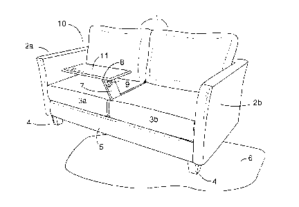
With reference to all figures presented within this submission, the tray
delivery
system has been designated by the reference number 8. As viewed in Figure 1,
the
tray delivery system 8 is presented in the open position and is placed in the
typical
location between two seating cushions 3a & 3b shown within a sofa 10. The sofa
10
shown is an example of the associated furniture to which the tray delivery
system 8 is
capable of being installed. Finishes to this associated furniture can include,
but are
_g_
CA 02275453 2001-04-03
not limited to wood, fabric and or leather. This sofa 10 style also includes
loose back
pillows 1, legs 4, a left arm 2a, and right arm 2b which can be placed on a
variety of
types of flooring 6. In furniture featuring greater than two seat cushions 3,
the tray
delivery system 8 can be placed between any two adjacent cushions 3. When the
tray
delivery system 8 is placed within associated furniture of chair styling, or
furniture
consisting of a single seat cushion 3, the tray delivery system 8, is placed
between the
seat cushion 3a or 3b and one of the arms 2a or 2b, subject to the orientation
of the
tray delivery system. Orientation is denoted as either left-hand facing or
right-hand
facing. The tray delivery system 8 in Figure 1, including all subsequent
figures,
depicts a left-hand facing orientation. Determining orientation of the tray
delivery
system 8 is subject to the direction and rotation of the tray 11. As shown in
Figure 1
from the three-quarter face on perspective, the support arm 7 is located
between two
cushions 3a & 3b with the tray 11 folding left over the left seat cushion 3a.
If the tray
delivery system 8 folds right, over the right seat cushion 3b, then this
orientation is
designated as right-hand facing.
Opening the tray delivery system 8 as shown in Figure 1 is accomplished
through a
series of steps involving support arm 7 and tray 11 rotation. The initial
storage
position consists of the tray delivery system 8 folded within the delivery
system slot
14 contained within the sofa's deck 13 as shown in Figure 4. While seated, an
individual reaches through the angular cavity area 12 of the seating cushions
3
grasping the rear top edge of the tray 11. The tray delivery system 8 is then
rotated
forward as shown in Figure 6, until the support arm 7 makes contact with the
sofa's
-9-
CA 02275453 2001-04-03
front facing 5. The tray 11 continues forward rotation until completely
vertical.
Completing this process, the seated individual folds the tray 11 downwards
over the
occupied seat. The tray delivery system 8 is now ready for standard use.
From the open position, the process of storing the tray delivery system 8
consists of
following the steps of extraction in reverse as depicted in Figure 2. An
individual in
the seated position grabs the tray 11 and lifts the tray 11 upward until it is
approximately perpendicular. At this point, the tray 11 is rotated towards the
back of
the sofa 20 and downward until making contact with the front facing 5. At this
stage,
the tray 11 is partially inserted into the delivery system slot 14 that was
cut into the
sofa's deck 13. In order to provide a clear view of the delivery system
storage area
14, the right seat cushion 3b and right loose back pillow lb have been omitted
from
Figure 2 and Figure 3. A seated individual now grasps either the support arm 7
or the
protruding portion of the tray 11, and begins to rotate the tray delivery
system 8
towards the back of the sofa 10 until both the tray 11 and support arm 7 fit
comfortably in the delivery system slot 14 located underneath the seat
cushions 3.
Figure 3 shows this range of motion as the tray delivery system 8 rotates
backwards
into the delivery system slot 14.
In order to provide easy deployment and storage of the tray delivery system 8,
modifications were made on both the left cushion 3a and right cushion 3b in
the form
of an angular cavity 12. Figure 4 provides an enlarged view of the left
cushion 3a on
a sofa 10 with the right cushion 3b removed. Figure 5 provides a front-on view
of the
-10-
CA 02275453 2001-04-03
two cushions 3a & 3b both on the sofa 10 which are portrayed transparent in
order to
reveal the space created with the angular cavities 12. The main benefit
achieved
through this configuration is that an individual's hand only reaches through a
minimal
amount of cushion 3a & 3b in order to grasp the tray 11, therefore making
rotation
motions easier to perform during opening and closing of the tray delivery
system 8.
For furniture consisting of greater than two seat cushions 3, the two cushions
3 in
which the tray delivery system 8 is placed between will contain the respective
angular
cavities 12. When a single seat cushion 3 exists, the angular cavity 12 is
associated
on the side of the seat cushion 3 that coincides with the location of the tray
delivery
system 8.
The smooth movement of the support arm 7 within the guide rail 21 a & 21 b is
achieved through an inserted dowel 16 equipped with stabilizing doughnuts 37
within
the guide rails straight hole grooves 26. The length of the straight hole
groove 26,
permits a wide range of possible positions for the tray delivery system 8. The
support
arm 7 maintains stability in any particular position through three components:
axm
block support 23, main contact block 24, and an L-shaped clip 25 which is
attached to
the main contact block with two screws 18. As the tray delivery system 8 is
extracted
from the storage area 14, the support arm 7 with all attached components,
rotates
towards the front of the sofa 10. This motion is depicted in Figure 6.
Once the support arm 7 makes contact with the sofa's front facing 5, the dowel
is
moved backward in order to accommodate individual body size variations as
shown
-11-
CA 02275453 2001-04-03
in Figure 7. With selected depth chosen by the seated individual, the support
arm 7 is
rotated forward engaging the main contact block 24 with the left guide rail
21a.
Additional reinforcement is accomplished with the L-shaped clip's 25 contact
with
the outer side of the left guide rail 21 a.
Two separate guide rail systems were developed for implementation within the
tray
delivery system 8. The configuration shown in Figure 6 depicts a straight hole
groove guide rail 21. The straight hole groove 26 permits the support arm 7 to
be
locked into place within the range of movement of dowel 16. The alternative
guide
rail system is similar to the straight hole groove guide rails 21 with the
addition of
notched teeth 34 along the top of the straight hole groove 26. These notched
teeth 34,
shown in figure 8 provide fixed set depth adjustment for the tray delivery
system 8.
This alternative provides set positions for the tray delivery system 8.
Additional
modifications to the tray delivery system 8 under this configuration include
lowering
the arm block support 23 and associated components (main contact block 24, L-
shaped clip 25) on the support arm 7 in order to compensate for the notched
teeth
height 34.
Guide rails 21a & 21b are secured to the sofa 10 through a series of eight
screws 35.
For each individual guide rail 21a & 21b, two screws 35 are used to secure
each guide
rail 21 to the front facing 5 of the sofa 10 and two screws 35 are used to
secure to the
rear facing 36 of the sofa 10. Placement and attachment of the guide rails 21a
& 21b,
to the sofa 10, is shown in Figure 5 with the tray delivery system 8 in the
stored
-12-
CA 02275453 2001-04-03
position. This method of attachment provides a secure foundation for the tray
delivery system 8 and can be easily modified to accommodate various types,
styles
and sizes of furniture.
Tray rotation is achieved through a hinge rotation device 9 located near the
top of the
support arm 7, allowing for the required range of motion to rotate the tray 11
upwards
and over a seated individuals lap. Figure 9 provides a clear view of the hinge
rotation
device 9. The lower flange 15b contains four holes. The largest hole is
located near
the center of the lower flange 15b which contains the hinge bolt 28 and Nut 27
that
fastens the rotation device 9 to the support arm 7. The remaining three holes
are used
to fasten the lower flange 1 Sb to the rotation disc 19 using three screws 18.
The upper flange 15a has two support beams 17 attach to the tray 11 via eight
screws
18. The support beams 17 fulfill two important roles. Firstly, these support
beams 17
increase the attachment's strength between the upper flange 15a and the tray
11.
Secondly, when the tray is in the open position, the support beams 17 make
contact
with the top of the support arm 7 which has a reinforcement plate 29 typically
made
of metal and attached to the top surface of the support arm 7. The location of
the
reinforcement plate 29, and its contact with the support beams 17, is clearly
shown in
Figure 10. The combination of support beams 17 and reinforcement plate 29
increases the maximum load capacity for the tray delivery system 8 and
minimizes
tray 11 wobbling as weight is applied.
-13-