Note: Descriptions are shown in the official language in which they were submitted.
CA 02275553 1999-06-18
DESCRIPTION
TITLE
Form with integrated card
TECHNICAL FIELD
The present invention relates to a form having an
integrated detachable card, it being possible for the
form to be of single-layer but. in particular multi-layer
construction.
The cards may be those which are present in the
form in a virtually finished state and only have to be
detached. However, there may also be cards which are
present in the fog not in their final layer construction
but in several parts and only have to be finally tailor-
made, for example by the user, when being detached, if
appropriate by the application of some personalization.
Since as a rule a folding operation is associated with
this, such cards are also referred to as butterfly cards.
In addition, the cards may be designed such that
they initially have the properties of self-adhesive
labels or allow self-adhesive labels to be produced from
them, for example by pulling off a release paper. The
cards may also be designed as so-called vignettes, which
are provided to be bonded behind a Fin a of glass, being
provided on their side facing the pane of glass with a
specific, if appropriate individual, item of information.
CA 02275553 1999-06-18
- 2 -
PRIOR ART
Forms with integrated cards of the abovementioned
type are known, for example from WO 95/20493 or
EP-A1-0 733 490. In the case of the known forms, there is
bonded onto the rear side of the primary form material a
carrier material which comprises a carrier layer and a
peelable glue layer. The card is produced directly in the
form in the region of the ca:crier material by stamping,
the stamping being carried out from the front side of the
form as far as the carrier layer of the carrier material.
The advantage which can be achieved with this design, and
which is based on the particular properties of the
peelable glue layer, is primarily that the card can be
stamped out in a web-free manner and completely around
the periphery. The peelable glue is set in such a way
that it essentially loses its. adhesiveness when the card
is detached.
Although suitable peelable glue systems of this
type can be implemented in accordance with various
principles, these are all associated with a not inconsid-
erable effort in production and processing. The known
peelable glue systems also exhibit a release-value
behavior which depends on ambient conditions such as
temperature and humidity, and are also therefore indus-
trially not easy to control.
In the case of the previousl}~ known forms, on the
one hand the overall thickness in the card region is
admittedly kept low by including the primary form mate-
rial in the card, but on the other hand the carrier layer
CA 02275553 1999-06-18
- 3 -
contributes substantially to this overall thickness. From
the point of view of processing the forms in printers, in
particular using the single-sheet process in laser
printers, an overall thickness which is as low as possi-
ble in the card area is desired.
DESCRIPTION OF THE INVENTION
The invention, as it is characterized in patent
claim 1, achieves the object of specifying a form with an
integrated detachable card which manages without peelable
glue and without a carrier layer which is not a constit-
uent part of the finished card., According to the inven-
tion, this is achieved by a form in which the card is
connected to the material surrounding it, at least partly
along its external margin in the form (card margin) via
a bridge which is designed asc an intended rupture line,
the material thickness along the bridge being con-
tinuously lower than the overall thickness of the form.
Preferred refinements and developments of the
invention are specified in the dependent claims.
The bridge is thus advantageously formed, for
example, by an inner or an outer part layer, all the
other part layers being severed from one or from both
sides of the form along the bridge on the card margin,
for example by being stamped. In this case, the bridge
can also or alternatively be formed ~_a residual thick-
ness between two cutting lines which are made from both
sides of the form, and are mutually congruent or at least
essentially mutually congruer~t.
CA 02275553 1999-06-18
- 4 -
The designs mentioned allow the desired retaining
value of the card in the form to be set well, to be
specific purely geometrically via the depth of the cut or
of the cuts or the residual thickness resulting therefrom
of the part layer which has been left intact, or via the
residual thickness between two cuts made from both sides
of the form. For example, a residual thickness in the
range between 10 ~, and 50 ~., in particular between 15 ~.
and 25 ~., has proven to be favorable, the optimum value
depending on the type of material and/or being determined
by the application.
In particular if-the form is stamped from both
sides and thus provided with incisions along the card
margin and the bridge, the card may be separated from the
form simply and without there being the risk that the
material will tear otherwise than along the bridge as a
predefined intended rupture line.
The bridge can be formed over its longitudinal
extent in a uniform and web-free manner, or else in cut
and web sections that alternate like a sawtooth or in the
manner of a perforation. However, as distinct from a
"classical" perforation, in this case the material is at
least partially cut even in the web sections, so that
only said residual thickness is still present in the
region of the webs.
By means of a structured or d~~erentiated design
of the bridge in this way, the retaining force of the
card in the fog may be set more precisely and more
finely, and good results with regard to its detachment
CA 02275553 1999-06-18
- S -
can also be achieved if the bridge is arranged in an
outer layer and the remainir.~g part layers are severed
only from the side opposite this layer.
By means of additional film covering layers,
applied on one or both sides to, for example, a support-
ing paper layer, it is possible to produce plasticized
cards, as in the prior art. Because of their rather
unfavorable tearing or tear propagation properties
compared to paper, however, the film layers are less
suitable for constructing the bridge. The bridge is
therefore advantageously cons~:.ructed, for example, in the
supporting paper layer and the film covering layers)
is/are completely severed along the bridge on the card
margin.
In the case where film covering layers are
present on both sides, if it i.s desired to avoid severing
these layers from both sides, it is then necessary for
one of these layers or a part layer to be used to form
the bridge. By structuring the bridge over its length, as
mentioned, in the manner of a perforation with very short
webs, however, good results with respect to the detach-
went of the card can also be achieved here, whilst
avoiding undesired tearing.
Using additional re7.ease layers or additional
release layer material, it ie~ also possible to implement
butterfly cards, cards containing sel~adhesive labels or
vignettes.
Since, by comparison with the previously known,
at least the carrier layer and the peelable glue layer
CA 02275553 1999-06-18
- 6 -
are dispensed with, it is possible to write on the cards
over the entire area on the front and rear side, even
when they are still integrated in the form. If film
covering layers are present, these may be specifically
treated if necessary for the purpose of writability, that
is to say, for example, provided with a matt finish.
The subject matter of the present invention is
also a method for producing the forms according to the
invention of the type previously described, wherein
according to patent claim 29:, in order to produce the
card, the form is stamped congruently or at least essen-
tially congruently from both sides, at least partly along
the card margin.
Stamping on both sides may be carried out on
individual forms or on continuous webs, in which the
forms are still coherent. It c:an be carried out from both
sides simultaneously in relation to the two sides or else
one after another. The requirements which result in this
case on the maintenance of register can in principle be
coped with.
The concept according to the invention is largely
independent of material and thickness. It functions just
as well in a simple paper as in a complicated multi-layer
construction.
In comparison to cards based on the peelable glue
principle, in spite of higher retai~:ing force, the card
can be removed from the forms according to the invention
without a curl effect, since the card virtually does not
have to be bent when being removed, but can simply be
CA 02275553 1999-06-18
pressed through.
Dispensing with carrier material and peelable
glue reduces the production costs by comparison with the
previously known forms.
Further refinements and advantages of the inven-
tion emerge from the following description of exemplary
embodiments in conjunction with the appended drawings.
BRIEF DESCRIPTION OF THE FIGCfRES
Fig. 1 shows, in plan view, a part of a form according
to the invention with an integrated card;
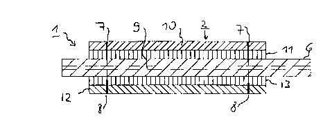
Fig. 2 shows, under a) and b) in section, a form
according to Fig. 1 which comprises only one
paper layer;
Fig. 3 shows, under a) and b) in section, a form
according to Fig. 1 which is provided with film
covering layers in addition to a supporting
paper layer;
Fig. 4 shows in section a foxy according to Fig. 4
[sic] , in which i:he bridge along the card
margin is formed by a separate part layer;
Fig. 5 shows in section a form according to Fig. 4, in
which, in order to construct a first type of
butterfly card, a release-layer material is
provided under the film covering layer on the
front side: . .
Fig. 6 shows in section, under a) and b), a form
according to Fig. 4 in which further part
layers are applied on the rear covering layer;
CA 02275553 1999-06-18
_ g _
Fig. 7 shows in plan view a part of a foz~ according
to the invention with an integrated butterfly
card of the second type or vignette;
Fig. 8 shows, in section under a) and b), a form
according to Fig. 7 in a design having an
integrated butterfly card of the second type;
Fig. 9 shows, in section under a) to e), a form acc-
ording to Fig. 7 in a design with an integrated
vignette;
Fig. 10 shows, partly in plan view of the front and the
rear side, and partly in section under a) to
f), a form having a card which comprises a
self-adhesive label covered by a release paper;
Fig. 11 shows, under a) to i), an embodiment corre-
sponding to Fig. 10, supplemented by a removal
aid for the card anal a pulling-off aid for the
release paper;
Fig. 12 shows, under a) to c), an embodiment corre-
sponding to Fig. 10, but in which the bridge is
formed by a part layer in the release paper;
Fig. 13 shows, under a) to i), an embodiment corre-
eponding to Fig. 12., supplemented by a removal
aid for the card and by a pulling-off aid for
the release paper;
Fig. 14 shows, under a) to j), an embodiment corre-
sponding approximately to ~3.g.. 13 , but in which
the pulling-off aid is designed such that the
self-adhesive label contained in the card can
if required also be detached separately from
CA 02275553 1999-06-18
_ g _
the form, that is to say without the entire
card;
Fig. 15 shows, under a) and. b), an embodiment in which
the self-adhesive label may likewise be det-
ached separately from the form, but on the
basis of other means;
Fig. 16 shows, under a) to c), in each case in section,
three further embodiment variants of forms
according to the invention having cards com-
prising self-adhesive labels;
Fig. 17 shows, under a) to c), in each case in section,
embodiments iri-which the bridge or a residual
thickness is produced by stampings from both
sides, which stampings are laterally offset
somewhat in relation to one another;
Fig. 18 shows, schematically, a stamping devices [sic]
for producing forms according to the invention;
Fig. 19 shows, under a) andl b), an embodiment in which
the part layer forming the bridge is an outer
layer and is intrinsically structured in the
manner of a perforation;
Fig. 20 shows an embodiment corresponding to Fig. 19 in
which additional film covering layers are
provided;
Fig. 21 shows, under a) to c), sheet-metal punches for
producing forms o:f the tags of Fig. 19 or
[lacuna] ;
Fig. 22 shows, under a) and. b), in each case in section
along approximately congruent stamping lines,
CA 02275553 1999-06-18
- 10 -
examples of bridges located on the inside which
are structured in the manner of a saw line or
perforation; and
Fig. 23 shows an embodiment in which the form is
pressed together wil:,h respect to its thickness
in the region of the card.
WAYS OF IMPLEMENTING THE INVEI~ITION
In Figure 1, 1 designates a form, which is
illustrated only partially i.n plan view on its front
side, and 2 a card which is integrated therein. The card
margin is designated by 3. i~ hole 4, through which a
section 5 of the card margin 3 is exposed, is stamped'out
adjacent to the card margin 3. The hole 4 facilitates the
removal of the card 2 and 'therefore forms a type of
removal aid.
Figures 2 to 6 show examples of possible layer
constructions of the form of Figure 1 in section, the
section in each case being made along the line A-A in
Figure 1.
In the example of F:Lgure 2, the form 1 is of
single-layer construction, that is to say it consists
only of a paper layer 6. According to Figure 2a), this is
stamped along the card margin. 3 both from the front side
(stamping line 7) of the form and also from the rear side
(stamping line 8) of the form as fag- as the depth of a
part layer 9 lying inside. Tlne two stamping lines 7 and
8 are carried out such that they run around the entire
periphery, are web-free and congruent. The part layer 9
CA 02275553 1999-06-18
- 1:L -
forms, along the card margin 3 between the two stamping
lines 7 and 8, a bridge which is designed as an intended
rupture line. By means of pressure on the card surface or
by gripping the card margin 5 in the region of the hole
4 stamped out as removal aid, this bridge can be des-
troyed and the card 2 removed from the form. Figure 2b)
shows the form with detached card 2.
The embodiment of Ficrure 3 shows a form of multi-
layer construction, but which is based on the same
principle as that of Figure 2, that is to say here as
well the card 2 is kept in the plane of the form by an
internal part layer 9 of a paper layer 6. Here, however,
additional film covering layers 10 and 12 are bonded to
the paper layer 6 on the front and rear side by means of
adhesive layers 11 and 13. The two stampings 7 and 8 are
carried out through these additional layers and thus
sever the latter completely along the card margin. Hy
this means, the detachment o~f the card is significantly
facilitated and it is in particular ensured that the
bridge formed by the continuous part layer 9 of the paper
layer 6 tears in the desired manner only along the card
margin. The tearing edge between the two film covering
layers always becomes frayed out slightly. Given a
suitable design, however, this fraying lies in the
microrange, can be detected only with magnification and
is virtually not perceptible in a ta~~ile manner. On the
other hand, however, the fra~~ing out is advantageous from
the point of view of bonding the adhesive exposed at the
film edges. Figure 3b) showFC the form 1 with the card 2
CA 02275553 1999-06-18
- 12 -
detached. The detached card ~;rirtually cannot be distin-
guished from a completely curt-out card according to the
prior art.
The additional layers 10-13 can be designed to be
of smaller area than the paper layer 6. It is sufficient,
as is indicated in Figure 1 by the broken line 14, if
said additional layers cover the region of the card 2
and, if appropriate, in addition the region of the
removal aid 4. In order to achieve a uniform thickness,
however, they could also be laminated over the entire
area to the paper layer 6. A uniform thickness has a
favorable effect on the stackability of the forms and
their processing in single-sheet printers.
In the embodiment of Figure 4, the bridge, via
which the card 2 is retained :in the form plane, is formed
by a separate part layer 15 which is bonded by means of
an adhesive layer 16 to the paper layer 6, here to its
rear side. The layer 15 is preferably a thin paper layer.
The two congruent stampings 7 and 8 are carried out as
far as the layer 15. In this embodiment it becomes clear
that the location and type of the part layer which has
not been stamped through and forms the bridge is variable
in the layer construction of the form.
Figure 5 shows an embodiment having a first type
of butterfly card. Given an otherwise identical construc-
tion as that of Figure 3 , a furthers piece of a release
material with a supporting layer 17 and a release coating
18 is inserted between the front covering layer 10 and
the front adhesive layer l:L, said release coating 18
CA 02275553 1999-06-18
- 13 -
facing the adhesive layer 11. Although the adhesive layer
11 has been drawn for illustrative reasons With an
unequal thickness, it may actually be of uniformly thick
design. The release material piece is somewhat smaller in
terms of area than the front. covering layer 10 or the
adhesive layer 11, and covers only the region which is
outlined in Figure 1 by the interrupted line 19 and which
also does not completely cover the region of the card 2.
In the zone of the card 2 which is designated by 20, on
the one hand the covering :Layer material 10 is as a
result directly bonded to the surface 21 of the paper
layer 6; on the other hand the card margin 3 and the
stamping line 7 following the latter run outside the
release material there. Otherwise, however, the release
material is completely severed by the stamping line 7.
On the basis of the .design described above, the
front film covering layer 10, together with the piece of
release material cohering thereto, can be bent up in the
region of the card 2, and the surface 21 of the paper
layer 6 partly exposed, for example for the purpose of
individual inscription. The inscription can subsequently
be sealed by bonding the fi7.m covering layer 10 to the
paper surface 21. For this purpose it is necessary only
to remove the piece of release material, and expose the
adhesive layer 11.
The exemplary embodiment of Figure 6 is likewise
based on that of Figure 3, only here in addition further
part layers 22-26 are provided on the rear side film
covering layer 12. The part layer 22 is a peelable glue
CA 02275553 1999-06-18
- 14 -
layer, and the part layer 2?. is, for example, a paper
layer, which can be provided with a specific imprint.
This is followed by an adhesive layer 24 and finally by
a release material having a release coating 25 on a sup-
porting layer 26.
This construction mak~ss it possible to remove the
release material 25/26 on the: rear side when the card 2
is detached, and to bond the card onto any desired
surface 27, like a self-adhe~cive label, by means of the
adhesive layer 25 which is exposed on said card. By
releasing the non-permanently set connection between the
peelable glue layer 22 and they film covering layer 12, it
is subsequently possible still to obtain a free, non-
self-adhesive card 2' having a, structure corresponding to
the example of Figure 3. In this case, the three layers
22-24 remain on the surface 2'7. Any inscription which is
applied to the layer 23 becomea visible. This is shown by
Figure 6b). The remaining part can be used, for example
as a control label 2" for the card 2'. The peelable glue
layer 22 is preferably set in such a way that, following
its separation from the film covering layer 12, it is no
longer adhesive.
Figure 7 shows, like Figure 1, a plan view of a
part of a form 1 according to the invention, but the
integrated card here is a butterfly card of the second
type or a vignette, which are presex~--in two regions 28
and 29 in the form 1 in the folded-out foxy.
Using Figure 8, a foam according to Figure 7 is
first described in a design with an integrated butterfly
CA 02275553 1999-06-18
_ 1~; _
card. The form 1 comprises, according to Figure 8a) , a
paper layer 30, to which a film covering layer 32 is
bonded on the rear side by means of an adhesive layer 31.
In the region 29, a release layer 33 is further inserted
between the paper layer 30 and the adhesive layer 31.
Corresponding to the exemplary embodiments previously
described, the form 1 is stamped from both sides, the
stamping lines 34 and 35 being carried out along the
outer margin 3' of the two card parts (card margin in the
form) in the regions 28 and 29, as far as into the depth
of a part layer 34 of the paper layer 30, in a manner
which runs completely around the periphery, is web-free
and congruent. The form material is stamped from the
front side additionally as far as into the depth of the
adhesive layer 31 along the line 37 between the two
regions 28 and 29 (stamping :Line 38).
In the case of the construction of Figure 8, in
a first step an auxiliary card 39, which can be used for
example as a coupon or control card, can be detached from
the region 29 of the form l., the bridge formed by the
part layer 36 of the paper layer 30 being destroyed along
the stamping lines 34 and 35 in this region. As a result,
the two layers 31 and 32 which lie underneath the latter
also lose their connection to the material surrounding
them in this region 29. As a result, these layers can be
folded over in a next step in the region 28 and bonded
there to the surface of t:he paper layer 30, as ie
indicated by the arrow 40. This results in a card which
is provided on both sides with film covering layers,
CA 02275553 1999-06-18
- 16 -
corresponding to that of Figure 3, which can finally be
detached from the form by destroying the bridge formed by
the part layer 36 of the paper layer 30 along the
stamping lines 34 and 35 in the region 28.
The embodiment of Fig,sre 8 has the advantage that
the surface of the paper layer 30 is exposed in the
region 28 and can be inscribed or printed individually
before the detachment of the card. In the finished card,
on the other hand, this sur:Eace is sealed by the film
covering layer 32 originating from the other region 29.
Instead of only one release layer 33, in the
embodiment of Figure 8 it is also possible for a release
layer material of multi-layer construction and of identi-
cal function to be used. In the region 29, the stamping
34 could also be left out, the auxiliary card 39 then
being dispensed with. In addition, it would be necessary
for the actual card to be detached downward from the form
in the folded-out state, and to be finally customized by
folding and bonding its two 'parts onto one another only
in the detached state.
Figure 9 shows a form according to Figure 7 in a
design with an integrated vignette, the layer construc-
tion being visible from Figure 9a). Said construction
largely corresponds to that of Figure 8a), only instead
of one release layer 33, two release layers 41 and 42 are
provided on either side of th.e adhes' :-~ layer 31 lying in
between. In addition, the form material is provided,
along the line 37 between the: two regions 28 and 29, with
a perforation 43, which is e;tamped through all the part
CA 02275553 1999-06-18
_ 1~~ _
layers.
The development to produce and to detach the
vignette is as follows: firstly, once more an auxiliary
card 39, which can be used for example as a coupon or
control card, is detached from the region 29 of the form
l, the bridge formed by the part layer 36 of the paper
layer 30 being destroyed along the stamping lines 34 and
35 in this region. As a result, the layers 31, 32 and 42
which lie below the latter also lose their connection to
the material surrounding thenn and, in a second step, can
be folded over into the region 28 and bonded there to the
surface of the paper layer 30, as is indicated by the
arrow 44 in Figure 9b). The resulting structure is shown
by Figure 9c). Proceeding from this structure, as a third
step a further folding operation is necessary in which,
according to arrow 45 in Fi<~ure 9c) , however, only the
two uppermost layers 32 and X62 are folded back once more
out of the region 28 into t:he region 29. The adhesive
layer 31 in this case remains on the surface of the paper
layer 30 in the region 28. The result of the second
folding operation is shown b~~ Figure 9d. Taken together,
the two folding operations (arrows 44 and 45) lead to a
transfer of the adhesive layer 31 from the region 29 into
the region 28. In the region 28, the desired vignette is
now already present and can lbe detached from the form by
destroying the bridge formed by the ~a~t layer 36 of the
paper layer 30 along the stamping lines 34 and 35 in the
region 28. Before said vignette is stuck, by means of the
adhesive layer 31 exposed on its surface, behind a pane
CA 02275553 1999-06-18
- 18 -
47 according to Figure 9e), the piece of covering film
48, which is still cohering to it via the perforation 43
and has previously been folded to and fro, is finally
separated. An inscription applied to the surface of the
paper layer 30 in the original form, in the region 28,
can be seen through the pane 47.
In the exemplary embodiments according to Figures
8 and 9, the part layers in each case bonded to the rear
side of the paper layer 30 are equally large in terms of
area as the paper layer itself, as a result of which the
form as a whole obtains a uniform thickness. However, if
appropriate to save material, the said part layers can be
selected to be smaller in teams of area than the paper
layer.
The exemplary embodiments explained below using
Figures 10 - 16 relate to all forms having cards which
comprise a self-adhesive label, as was already the case
per se in the case of the ea~nbodiment of Figure 6. The
embodiment of Figure 10 can consequently also be derived
from that of Figure 6 by leaving out various layers.
In the example of Figure 10, a release paper
having a release layer 52 and a supporting layer 53 is
bonded onto the rear side o!: a paper layer 50 only by
means of an adhesive layer 51. The form is stamped
congruently from both sides as far as into the depth of
a part layer 54 in the pape:c layer -50, as is shown by
Figures l0a) - c). Figure lOd) corresponds to Figure
lOb). Figure l0e) shows the form with detached card 55.
In Figure lOf), said card has been separated into a
CA 02275553 1999-06-18
- 19 -
simple self-adhesive label 56 and a release paper part
57.
In Figure 11, the example of Figure 10 ie supple-
mented on the one hand by a removal aid 58 for the card
55 and on the other hand by a pulling-off aid 59 for the
release paper 57. In order to indicate the design or
manufacture of these aids, Figures lla) and lld) in each
case illustrate plan views of the front side of the form,
and Figures llc) and llf) in. each case illustrate plan
views of the rear side of t:he form. Between the front
plan view and the rear plan v~.ew, sectional views C-C and
D-D are illustrated in Figures llb) and lle), using which
the stamping depth of the stamping lines drawn in the
plan views can be seen in each case.
Thus, the form of Figure 11 is stamped from both
sides congruently as far as into the depth of the part
layer 54 in the paper layer 50, outside the aids, desig-
nated by 58 and 59, according to Figures lla) - c). This
applies correspondingly to t:he removal aid 58. In the
region of the pulling-off aid 59, the form has by con-
trast not been stamped at al.l from the rear side. From
the front, the form has been stamped in this region along
the section 60 on the card margin as far as into the
depth of the release layer 52, and fully stamped through
along the outer line 61 framing the region of the
pulling-off aid 59. As a result .-,f- these stampings,
differentiated with respect to their depth, as shown by
Figure llg), firstly a stamped portion 62 can be removed
from the region of the removal aid 58 as a result of
CA 02275553 1999-06-18
- 20 -
which a hole is produced in the form and a section 63
(Figure lla) of the card margin is exposed. By gripping
the card 55 at this section 63, said card can simply be
detached from the foz~. The detached card 55 is shown in
Figure llh) . The pulling-of f aid 59 forms on the detached
card a type of finger tab, which can be gripped easily
and used for separating the release paper part 57 from
the self-adhesive label 56, as can be seen using Figure
lli) .
In the embodiment of Figure 12, the continuous
part layer 64 forming the bridge is a part layer of the
supporting layer 53 of the release paper 52/53. Other-
wise, it corresponds to the embodiment of Figure 10~.
The example of Figure 13 combines the concepts of
the embodiments of Figures 11 and 12, that is to say that
here the continuous part layer 64 forming the bridge in
the supporting layer 53 of the release paper and, in
addition, a removal aid 58 a:nd a pulling-off aid 59 are
provided. Differing from the example of Figure 11, the
form has been completely stamped through in the region of
the removal aid 58, however, so that the stamped portion
62 already loses its connection to the material surround-
ing it during the production of the form and falls out of
the form. In the example o1. Figure 11, this could of
course be carried out in the same manner.
The embodiment of Figure l~~r- differs from that
according to Figure 13 only with regards to the design of
the pulling-off aid 59. In th.e region of this pulling-off
aid, and projecting beyond the latter somewhat in terms
CA 02275553 1999-06-18
- 21 -
of area, a release coating 65 has been applied locally on
the rear side of the form bel:ore the application of the
adhesive layer 51 and of the: release paper 52/53. The
local release coating 65 can be seen, inter alia, in
Figure 14c). Then, in addition to the stampings from the
front, which are carried out according to Figure 13 , a
stamping is carried out from the rear side of the form
along a line 66 as far as the' paper layer 50, as can be
seen in Figure 14e). The stamping line 66 runs completely
in the region of the card. As a result of this stamping
technique, as well as a result of the release properties
of the local release coating E>5, a stamped portion 67 can
be removed in the region of ~;.he pulling-off aid 59 and,
as a result, an approximatel~,r half-moon-shaped gripping
zone 68 can be exposed on the rear side of the card
between the card margin and the stamping line 66, as is
shown by Figure 14g).
With respect to the removal of the card 55 or of
the self-adhesive label 56, two options now arise from
the gripping zone 68: the option illustrated in Figure 14
under h) and i) essentiall.y corresponds to that of
Figures 11 - 13, that is to e~ay in this case the card 55
is removed completely from the form in a first step,
using the removal aid 58, and only subsequently in a
second step is the label 56 separated from the piece of
release paper 57. By means of pressuza from the rear onto
the gripping zone 68 mentioned, the self-adhesive label
56 can also be removed from the form separately, that is
to say without the piece of release paper 57, the latter
CA 02275553 1999-06-18
- 22 -
remaining in the form. This is illustrated in Figure 14
under j). A later additional removal of the piece of
release paper 57 is of course' likewise still possible.
It would also be possible to achieve separate
removability of the self-adY;~esive label 56, proceeding
from the embodiment of Figure 13, in that, as is shown in
Figure 15 only under a) and. b), in one corner of the
card, from the rear side of the form, a T-shaped stamping
70 is made in the release paper 52/53, and from the front
side of the form a short incision 71, adjoining the foot
of the T, is made, carried out through all the layers. In
the case of this configuration, in order to detach the
self-adhesive label separately, pressure with a finger on
the corner of the card provided with the T-shaped
incision is sufficient.
Figure 16 shows, under a) - c), three variants
which can likewise be used within the context of the
exemplary embodiments described above:
a) firstly illustrates that the release paper
52/53 can also project somewhat on all sides in terms of
area beyond the adhesive layer 51. This makes it possible
to counteract effectively the emergence of adhesive of
the adhesive layer 51 beyond the margin of the release
paper 52/53, and the risk, caused by this, of sticking of
several stacked forms. However, only specific types of
adhesives show any tendency at all :o flow out in this
way.
In Figure 16b) the paper layer is laminated over
the entire area to the adhesive layer 51 and the release
CA 02275553 1999-06-18
- 2a -
paper 52/53, an option which has already been agreed
(sic]. Although in this case more coating material is
needed, this results in the advantage of a uniform
thickness over the entire region of the form.
Figure 16c) shows a.n embodiment in which the
stampings to produce the card 55 are carried out outside
the region of the adhesive 51 and the release paper
coating 52/53.
In the examples according to Figures 17 a)-c), in
which for reasons of a simple illustration only one paper
layer 80 is provided, the two-sided stamping 81 on one
side and 82 on the other side in order to produce the
card 83 are not carried out e:Kactly, but only essentially
congruently, that is to say they are laterally offset
somewhat in relation to one another. The stamping 81 is
made down to a depth T1, and the stamping 82 is made down
to a depth T2. The thic:cneas of the paper layer is
designated by d. '
In the example of Figure 17a) , T1 + T2 < d, so
that here, as in the above-.described exemplary embodi-
ments, a part layer 84 that: is located on the inside
remains not stamped through and forms the desired retain-
ing bridge.
In the example of Figure 17b) , Tl + T2 - d, so
that the two stampings reach down to the same depth in
the paper layer 80. A continuous paz~ layer that is not
stamped through is no longer present here. Nevertheless,
as a result of the lateral offset of the two stamping
lines 81 and 82 there is sti:Ll a residual thickness that
CA 02275553 1999-06-18
- 24 -
forms a bridge and retains the card 83 in the form,
although this residual bridge is located horizontally in
the form instead of vertically or essentially vertically
as in the previous examples.
In Figure 17c) T1 + T2 > d, so that the two
stampings 81 and 82 even mutually overcut each other.
However, even here there is still a residual thickness
between the two stampings.
Of course, the effective residual thickness also
still depends on the mutual lateral offset of the two
stampings 81 and 82, which in addition to the stamping
depths forms an additional, independent parameter, via
which the residual thicknes s can be controlled and
adjusted in accordance with the respective requirements.
Figure 18 shows, schematically, a device with
which the congruent or essentially congruent stamping on
both sides is possible in order to produce forms of the
type according to the invention in one operation. 90 and
91 designate two magnetic cy:Linders which have at their
ends in each case rollers 92 and 93 of relatively large
diameter which run on one another. 94 and 95 designate
thin, metallic stamping sheet;a, which are placed onto the
surface of the two magnetic c~tlinders 90 and 91 and stick
to the latter magnetically. Tlhe stamping sheets 94 and 95
are provided in a known way with elevated, sharp cutting
webs 86 and, with respect to these .~:~ebs, are at least
partially of mirror-image design. The two stamping sheets
can therefore be positioned on the magnetic cylinders 90
and 91 in such a way that corresponding webs lie exactly
CA 02275553 1999-06-18
- 25 -
or at least essentially opposite one another. The diame-
ters of the magnetic cylinders 90, 91, of the rollers 92,
92 [sic], the thickness of the stamping sheets 94, 95 and
the height of the cutting webs is selected such that a
residual thickness b of approximately the magnitude of
the thickness of a part layer serving as bridge remains,
for example, between cutting webs which lie directly
opposite one another.
Figure 19 shows an embodiment which once more has
only one paper layer 100. A;s distinct from the above-
described examples, the bridge holding the card 101 is
formed here in an outer part layer 102 of the paper
layer, to be specific by a single stamping 103 made~from
only one side of the paper layer. The stamping 103 is
also made in such a way that the bridge that results in
the outer part layer 102 is interrupted in the manner of
a perforation, as is shown by Figure 19b), in which a
section E-E along the stamping line 103 is illustrated.
The region severed by the stamping 103 is illustrated
without hatching in Figure 19b). Along the stamping line
103, completely cut-through sections 104 alternate with
webs 105, which on their own still befit the retaining
function. The height of the webs 105 corresponds pre-
cisely to the thickness or residual thickness of the part
layer 102, which is about 50 u, for example.
Although in Figure 19b) the-fully cut-through
sections 104 and the webs 105 are illustrated as having
a coincident length, they are preferably made diffe-
rently, to be precise the cut-through sections 104 are
CA 02275553 1999-06-18
- 26 -
made several times longer than the webs 105. The latter
are selected to be as short as possible for the res-
pective material, in order that when the card 101 is
detached the tear strictly follows the predefined line,
and tearing in a manner deviating from this line is
avoided. According to available experience, webs 105 of
about 0.1-0.3 mm length alternating with fully stamped-
through sections 104 of about 0.5-1.0 mm length are
already sufficient still to mold the card 101 firmly in
the form 100 (the card 101 is held sufficiently firmly in
the form, for example, when t:he latter can be deflected
under tension around a deflection roll of 22 mm diameter
without the card 101 becomincL detached in the process).
On the detached card 101, webs which are so narrow and
also low, because of the resicLual thickness that is still
present, are hardly possible to make out optically or by
touch, and therefore also do not have a very disturbing
effect, as distinct from the "classic" perforation webs,
whose height always corresponds to the complete material
thickness. The great advantage of the embodiment of
Figure 19 resides in the fact. that, in order to produce
it, it is necessary only to stamp from one side.
The detachment of the card 101 is further facili-
tated by the fact that the form material is fully stamped
through in each case in the four corner zones 106, so
that the bridge is restrict~sd to p..~ t of the straight
sections of the card 101. In addition, a removal aid of
the type already described could also be provided in the
form of a hole adjoining the card 101, as shown, for
CA 02275553 1999-06-18
- 27 -
example, by Figure 1.
With regard to processing the forms in printers
or the like, for example predominantly in portrait
format, the retaining value of the card 101 in the form
100 in the longitudinal and transverse direction can also
be set differently by means of a different choice of the
cut/web ratio on the longitudinal and the transverse
sides of the card 101.
Figure 20 shows an embodiment corresponding to
Figure 19, only here the paper layer 110 is further
bonded on the front and rear side to foil covering layers
116 and 117. The corresponding contact-adhesive layers
are designated by 118 and 119., The part layer 102 forming
the bridge is formed here by the lower film layer 117,
the bridge once more being intrinsically structured by a
cut/web sequence. In spite of the rather unfavorable
tearing properties of plas~ic films, even in the case of
this embodiment the card may be detached cleanly from the
form, provided only that sufficiently short webs of the
order of magnitude of the already mentioned 0.1 mm are
used, and the cut/web ratio is about 6:1. The film
considered for the film covering layers 116 and 117 is,
for example, a biaxially stretched polyester film of
50 ~m thickness.
In order to produce the stampings with differen-
tiated stamping depth that are prow = :ed in the embodi-
ments of Figures 19 and 20, special sheet-metal punches
are necessary. Such a sheet-metal punch 120 is shown, for
example, by Figure 21a) . In each case only part of the
CA 02275553 1999-06-18
- 28 -
sheet-metal punch 120, with a short section of a stamping
web 121, is in each case illustrated in Figure 21a). Said
stamping web 121 stands out above the remaining level of
the sheet-metal punch 120, in the region of which it are
[sic] still just about 0.1 mm thick, has an approximately
triangular cross section and is of toothed design. The
height of the web 121 is for example 0.44 mm in the
region of the teeth 122 and, :Ln the region of the inter-
spaces 123, about half of this, that is to say about
0.22 mm.
In the case of the sheet-metal punch of Figure
21 a), starting from a continuous web 121, the material
in the interspaces 123 has beesn taken away horizontally,
which is quite difficult to carry out but still possible,
for example by milling, given the mentioned dimensions of
the web and the mentioned preferred dimensions of the
teeth and the interspaces. However, in this case an
actual sharp cutter in the in~terspaces is lost. By means
of a sheet-metal punch 120 designed in this way, the form
material, for example in the embodiment of Figure 19, is
more squeezed away and/or compressed than cut in the
region of the webs 105, that is to say where it is not
completely cut through by the: sharp teeth 122, but this
has not proven to be critical.
However, in the embodiment of Figure 20, the
rather blunt cutter in the interspacaes- 123 also readily
allows the film covering layer 117 to be stamped a little
further at the same time, even in the region of the webs
105, which might be of advantage. Using a sheet-metal
CA 02275553 1999-06-18
- 29 -
punch of the type according to Figure 21b), however,
this would also be possible :in that in the case of this
sheet-metal punch 120' a cutter is formed even in the
interspaces 123' between the: teeth 1221. However, the
sheet-metal punch 1201 of F~.gure 21b) can be produced
only with a high outlay.
A compromise between the sheet-metal punches of
Figure 21a) and Figure 21b) :is shown by Figure 21c). In
the case of the sheet-metal punch 120= illustrated here,
there is also a cutter in tlhe interspaces 1232 between
the teeth 1222, although this cutter also runs trans-
versely with respect to l:he direction of the stamping web
1212. However, a cutter of this type may once more be
produced comparatively simply using a profiled disk mill,
as is depicted, for example, in schematic form alongside
Figure 21c) and is designated by 130.
Figure 22 shows, under a) and b), two cuts
corresponding to Figure 19b), only here the bridge is in
each case located once more in the interior of a single
layer 140 and to this extent, for example, stamping from
both sides is necessary for its construction. As in the
example of Figure 19 or 20, tlae bridge is also inherently
structured once more, to be specific in the manner of a
saw line in Figure 22a) and in the manner of a perfo-
ration in Figure 22b).
Figure 23 shows a fu=-ther seut:ion through a form
150 according to the invention, with a supporting paper
layer 151 and foil covering layers 152 and 153 on both
sides, these essentially covering only the region of the
CA 02275553 1999-06-18
- 30 -
card 154. The foxy 150 is now pressed together in the
region of the covering layers 152, 153, so that its
overall thickness in this region is approximately equal
to its thickness outside this region. Such a design is
possible, inter alia, becausE_ of the advantageous con-
struction of the form according to the invention without
using a carrier layer which is not a constituent part of
the finished card. Forms according to Figure 22 may be
stacked better than those of a nonuniform thickness.
The pressing together of the form in the region
of the covering layers can be~ carried out in a separate
operation, but advantageously directly in conjunction
with the stamping, just in the way that squeezing and/or
compressing the form material in the region of the
stamping webs was already mentioned in the case of
stamping using the sheet-metal punch illustrated in
Figure 21a). In principle, fo:r example, a device accord-
ing to Figure 18 would be suitable for combined stamping
and compressing but, with regard, for example, to the
embodiments according to Figure 19 or 20, it would not
necessarily be the case that both punches would have to
have stamping webs.
The bridge could also be implemented by quite
other means. For example, it would be conceivable to
introduce an adhesive into l:he stamped cut during the
stamping operation, this adhesive aGn~antageously having
a certain brittleness after curing. In this case, it
would be possible to stamp tlhrough completely from only
one side. It is also not necessary to carry out the
CA 02275553 1999-06-18
- 31.
stamping in the final layer structure. The necessary
severing steps could be carx-ied out, for example, pre-
viously in individual part layers or groups of part
layers, before their lamination. Finally, the embodiments
described above are not intended to be final. In par-
ticular, it is also possible to use specific features of
individual types of embodiment in other types of
embodiment.