Note: Descriptions are shown in the official language in which they were submitted.
. ~ ; CA 02275831 1999-06-21
1
The present invention concerns a rotor for the treatment of a liquid such as
molten
metal by the addition of gas and/or particulate material, which rotor
comprises a
hollow rotation body with openings in the base and side which is mounted on a
shaft
and driven via the shaft by a drive unit and which is designed to be lifted
out of and
lowered into the liquid.
Equipment and methods have previously been known for treating a liquid and
adding
particulate material to it as stated above. The applicant's own Norwegian
patent no.
155.447 describes a rotor for treating a liquid and adding material to it in
which the
rotor comprises a rotationally symmetrical hollow body and in which the
material is
added to the liquid via a hole drilled in the rotor shaft and emerges through
holes in
the side of the hollow body together with the liquid, which is sucked in, by
means of
centripetal force, through an opening in the base and circulated through the
body.
This rotor produces a high liquid treatment capacity, i.e. the admixture of
gas or
particles, with very little agitation or turbulence in the liquid.
A general requirement for rotors for liquid treatment, in particular treatment
of molten
metals, is that the admixture of gas or particulate material is efficient.
However, it is
also desirable to avoid the creation of a great deal of agitation or
turbulence which
leads to an agitated surface and vortices in the liquid and which thus leads
to
increased admixture of gas from the surroundings (atmosphere).
The present invention represents a solution with rotors for liquid treatment
in which
the efficiency of the admixture of the gas or particles to a liquid is almost
doubled, but
in which the agitation is unchanged compared to the solution shown in the
applicant's
own Norwegian patent. Moreover, the present invention represents a solution
with
CA 02275831 2006-10-12
28116-1
2
rotors in which the gas/particle requirement (consumption)
is more than halved.
The invention may be summarized according to one
aspect as a rotor for treating liquid, said rotor
comprising: a hollow rotation body defining an interior
space and having an open lower end; a rotatable shaft
connected to an upper end of said hollow rotation body, said
shaft having a longitudinal flow passage communicating with
the interior space of said hollow rotation body; at least
one partition member disposed in the interior space of said
hollow rotation body, said partition member extending from
an interior peripheral surface of said hollow rotation body
so as to define a central chamber and at least one annular
chamber between the interior peripheral surface of said
hollow rotation body and an outer peripheral surface of said
partition member; at least one hole formed in a side wall of
said hollow rotation body and communicating with the annular
chamber; and at least one hole formed in said partition
member and establishing communication between the annular
chamber and the central chamber, wherein additive material
can be supplied to the annular chamber and the central
chamber via the longitudinal flow passage formed in said
rotatable shaft and the hole formed in said partition
member.
According to another aspect the invention provides
a rotor for treating liquid, said rotor comprising: a
hollow rotation body defining an interior space and having
an operi lower end; a rotatable shaft connected to an upper
end of said hollow rotation body, said shaft having a
concentric longitudinal flow passage communicating with the
interior space of said hollow rotation body, and at least
one flow passage that is radially spaced from the concentric
longitudinal flow passage and communicating with the
CA 02275831 2006-10-12
28116-1
2a
interior space of said hollow rotation body; at least one
vertical partition member disposed in the interior space of
said hollow rotation body, said partition member extending
from an interior peripheral surface of said hollow rotation
body so as to define a central chamber and at least one
annular chamber between the interior peripheral surface of
said hollow rotation body and an outer peripheral surface of
said partition member; and at least one hole formed in a
side wall of said hollow rotation body and communicating
with said annular chamber; wherein gas and particulate
material can be supplied to the annular chamber and the
central chamber via the concentric longitudinal flow passage
and the radially spaced flow passage, respectively.
According to another aspect the invention provides
a rotor for treating liquid, said rotor comprising: a
hollow rotation body defining an interior space and having
an open lower end; a rotatable shaft connected to an upper
end of said hollow rotation body, said shaft having a
longitudinal flow passage communicating with the interior
space of said hollow rotation body; a plurality of
concentric partition members disposed in the interior space
of said hollow rotation body so as to define a central
chamber and a plurality of annular chambers, wherein each of
said partition members includes a cylindrical portion; at
least one upper through hole formed in a side wall of said
hollow rotation body and communicating with said central
chamber; and a plurality of holes formed in the side wall of
said hollow rotation body and communicating with said
annular chambers, respectively.
The present invention will be described in the
following in further detail using examples and with
reference to the attached drawings, where
CA 02275831 2006-10-12
28116-1
2b
Fig. 1 shows a known rotor, as described in the
applicant's own Norwegian patent no. 155.447, seen a) in
cross-section and b) from above.
Fig. 2 shows a rotor in accordance with the
present invention seen a) in cross-section, b) from above
and c) from the side.
Fig. 3 shows an alternative embodiment of the
rotor shown in Fig. 1 in accordance with the present
invention seen a) in cross-section, b) from above and c)
from the side.
Fig. 4 shows another alternative embodiment in
which, instead of partition walls, an internal rotor is
used.
Fig. 5 shows another embodiment of a rotor in
accordance with the present invention with several partition
walls seen in cross-section.
Fig. 6 shows diagrams of results from comparative
tests at three different RPM values.
CA 02275831 1999-06-21
3
As stated above, Fig. 1 shows a known rotor as described in the applicant's
own
Norwegian patent no. 155.447. The rotor consists of a hollow, rotationally
symmetrical body which has a smooth surface both externally and internally and
which is provided with openings 5, 9 in the base and sides. The body 1 is
connected
to a shaft 2 which, in turn, is driven by a drive unit (not shown). Gas and/or
particulate material is/are supplied to the rotor through a drilled hole 3
and, when the
rotor is in operation, i.e. when the rotor is rotating, the gas, and the
liquid which is
sucked into the rotor through the hole 5 in the base, will be pressed out
through the
openings 9 in the side and will be finely distributed in the liquid.
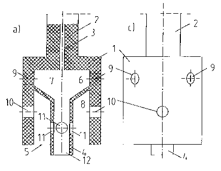
Fig. 2 shows a first example of a rotor in accordance with the present
invention. It
comprises a rotationally symmetrical body 1, preferably cylindrical, which has
a
smooth surface externally and internally and which is connected to a shaft 2
with a
coaxial drilled hole 3 for the supply of gas and/or particulate material. The
shaft 2 is
connected to and driven by a drive unit (not shown).
The special aspect of the present invention is that the rotation body 1 is
provided with
an internal, rotationally symmetrical partition wall 4 which extends just
below the
opening 5 in the body 1 and which, at its upper end, extends outwards in a
funnel-shaped part 6 and is fastened to the body 1 internally. The partition
wall 4 thus
defines an internal, centric cavity 7 and an annulus 8. In the example shown
here, the
body 1 is provided with four upper holes 9 which correspond to the centric
cavity 7
and four lower holes 10 which correspond to the annulus 8. Moreover, the
partition
wall 4 is provided with four holes 11 which form a link between the centric
cavity 7
and the annulus 8. The holes 9, 10, 11 can be arranged along the same vertical
line
or can be offset along the circumference of the rotor.
The rotor in accordance with the present invention functions as follows: the
rotor is
lowered into a liquid, for example molten metal, and is caused to rotate. The
liquid
will now, on account of the rotation of the rotor and the consequent
centripetal force
produced in the liquid, be sucked up, partially through the annulus opening 5
formed
between the partition wall 4 and the wall of the body 1, partially through the
opening
CA 02275831 1999-06-21
4
12 for the centric cavity 7 formed by the partition wall 4, and will be pumped
out
through the holes 11 and 10. Gas and/or particles which is/are supplied
through the
drilled hole 3 in the rotor shaft will, at the same time, partially be pressed
through the
upper holes 9 and partially through the lower holes 11 in the rotor wall and
the
partition wall 4. The gas which flows through the holes 9 will immediately be
broken
down into small gas particle fractions on the outside of the hole on account
of the
friction against the liquid on the outside of the rotor. The gas, together
with the liquid
which flows out through the holes 11, will be partially broken down and flow
up
towards the lower holes 10 in the rotor wall 1 and will be further broken down
into
small gas particle fractions immediately on the outside of the holes 10 in the
same
way as the gas which flows through the holes 9.
Fig. 3 shows an alternative embodiment of the solution shown in Fig. 2. The
rotation
body 1, the partition wall 4 and the upper and lower holes 9 and 10 are the
same.
The difference is that the holes 11 in the partition wall 4 have been removed.
Instead,
gas is supplied to the annulus 8 via drilled holes 13 in the wall 14 in the
rotor 1 and
shaft 2. Gas is supplied to the centric chamber 7 through the centric drilled
hole 3 in
the shaft 2 in the same way as in the example shown in Fig. 2.
In this example, the liquid will be sucked up into the centric chamber and
flow out
through the upper holes 9 together with the gas supplied through the drilled
hole 3,
and the liquid which is sucked up into the annulus 8 will flow out through the
lower
holes 10 together with the gas supplied through the drilled holes 13 in the
shaft 2 and
the rotor wall 14. The principle and method of operation are otherwise the
same as in
the example above. This solution shown in Fig. 3 is somewhat more expensive to
produce than the solution shown in Fig. 2 as a result of the drilled holes 13
in the
rotor wall/shaft. However, the efficiency in connection with the admixture of
gas is
somewhat higher.
The present invention, as it is defined in the claims, is not limited to the
examples
shown in the drawings and described above. For example, instead of partition
walls
which are permanently connected to the rotation body 1, a second rotationally
CA 02275831 1999-06-21
symmetrical body 16 can be arranged inside the cavity in the rotation body 1
by
means of a coupling piece 15 or another method, as shown in Fig. 4. The wall
of the
second rotation body 16 thus forms a partition wall 4. It is expedient for the
second
rotor not to be screwed completely in so that an opening 17 between the rotors
is
formed. This allows the gas for the outer chamber 8 to be supplied via the
shaft
drilled hole 3 and through the gap 17 between the two rotors.
Moreover, the present invention is not limited to one partition wall. It may
have two or
more partition walls or internal rotors. Fig. 6 shows an example of a rotor 1
in which
three partition walls 4 are used to divide the internal cavity in the rotor
into a centric
chamber 7 and three annuli 8 to which gas can expediently be supplied in the
same
way as shown in Fig. 2 or 3 (not shown in further detail).
With several partition walls, the efficiency can be further improved in
comparison with
the solutions shown in Figs. 2 and 3 and the consumption of gas/particles will
be
further reduced.
Tests:
Comparative tests were performed with a known rotor as shown in Fig. 1 and a
new
rotor in accordance with the present invention as shown in Fig. 3. The tests
were
based on the removal of oxygen from water using nitrogen gas.
The rotors were tested in a container in a water model with water flow of 63
I/min.
The rotors which were tested were in the scale 1:2 in relation to standard
size. The
external dimensions were the same and the holes in the base and side had the
same
diameter.
The rotors were driven by a motor of 0.55 kW at 910 RPM at 50 Hz. The RPM were
regulated using a 3 kW regulator of type Siemens Micromaster with a variation
range
of 0-650 Hz.
CA 02275831 1999-06-21
6
Nitrogen gas from a 200-bar, 50-litre nitrogen bottle was used and the gas was
supplied through the drilled hole in the rotor shaft via a reduction valve and
rotameters of type Ficher and Porter. The oxygen in the water was measured
with an
oxygen meter of type YSI model 58 (digital meter).
Furthermore, a water meter of type 5px (Spanner-Pollux GmbH) with a capacity
of
2.5 m3/h was used to measure the water quantity.
Moreover, a digital tochmeter of type SHIMPO DT - 205 was used to determine
the
RPM.
The two rotors were tested in the same container under the same conditions
with a
water flow of 63 I/min. After adjusting the water quantity, each rotor was
started and
the RPM were regulated to the desired speed. The oxygen measurement and
timekeeping were started as the supply of nitrogen gas was switched on. Three
different RPM values were used during the tests, 630, 945 and 1071 RPM, which,
for
rotors in the scale 1:1, would be equivalent to 500, 750 and 85 RPM
respectively.
Moreover, five different gas quantities were used during the tests: 12, 6; 25,
2; 37, 8;
50, 4 and 63 IN/min.
For the rotor in accordance with the present invention as shown in Fig. 3, the
gas
was introduced in four different ways:
- Gas only in the upper row of holes
- Gas only in the lower row of holes
- Equal gas quantities in both rows of holes, a total of: 12, 6; 25, 2; 37, 8;
50, 4;
63 IN/min.
- Double gas quantities, i.e. in each row of holes: 12, 6; 25, 2; 37, 8; 50, 4
and
63 IN/min.
. ; CA 02275831 1999-06-21
7
The results of the tests are shown in Fig. 6, which shows three diagrams, one
for
each RPM value. The known rotor as shown in Fig. 1, which, in the diagrams, is
designated the "standard rotor", was, until the present invention was
conceived,
considered to be the best on the market in terms of efficiency together with
low
turbulence and agitation.
In the tests, it was possible to see that the agitation and turbulence in the
liquid
(water) were just as low with the new rotor in accordance with the present
invention.
The diagrams show, however, that the efficiency of the new rotor, measured as
oxygen removed from the water, is nearly twice that of the known rotor at low
quantities of nitrogen gas supplied and is improved by approximately 50% at
the
highest quantity of nitrogen gas supplied. The diagrams also show that it does
not
matter greatly where the nitrogen gas is supplied in the rotor, i.e. whether
it is
supplied to the upper or lower row of holes or to both rows of holes
simultaneously.
This is on account of the good bubble distribution achieved with the new rotor
and the
fact that part of the gas is pressed back into the rotor before being
distributed out
through both rows of holes.