Note: Descriptions are shown in the official language in which they were submitted.
CA 02276482 2003-06-09
Wo 98!30476 PCTIUS98/0010'7
"Conveyor Having Serpentine Capabilities"
Technical Field
This invention relates generally to automated conveying
and sorting of items such as packages from one or more
loading sites to a variety of output destinations, and more
particularly relater to a conveying system which can convey
packages along a curved or serpentine path and eject thf:m
from said path.
Background of the invention
lVlodern high volume package delivery systems often
include package conveying systems that accept packages from
one or more loading stations, and transport the packages to a
variety of output destinations such as chutes, bins, and
subsequent conveyor systems.
One of the most conventional types of conveyors is a
belt conveyor, which includes the use of an endless flexible
belt which passes over at least two cylindrical rollers, one of
which. is a drive roller. Packages are placed atop the
upwardly-directed "working" surface of the belt conveyor, and
are transported in a generally str4ight direction from end of
the conveyor to the other.
CA 02276482 2003-06-09
2
Although such conventi<~nal be It conveyors have advantages, including
simplicity,
they also have disadvantages in that they conventionally only provide a
"straight-line"
transporting feature. 'This can be restrictive to package delivery systems
designers who may
have the need to move a package <>r rather product from an origin through a
tortuous, curved,
path to a destination.
Therefore, it has been known in the pri<fr art to provide flexible conveyor
chains such
as shown in U.S. Patent No. 3,7 76,349 to Kampfer, entitled "Fabricated
Conveyor Chain",
which discloses the concept of providing a fabricated tlexible conveyor chain,
which includes
a plurality of link units 11 linked ~x~gether by a plurality of pivot pins 12.
Although the pivot
pins 12 provide a linking feature hetween the link units, they fit loosely
enough within their
mounting holes to allow sideward relative pivoting of the link units. A
similar type of "hard
pin" connection is disclosed in t~l.S. Patent No. 3,262,5S0 to Kampfer,
entitled "Conveyor
Chain", in U.S. Patent No. 2,884, II 18 to VWilliarns, entitled "Articulator
Conveyor Chain" and
also in U.S. Patent No. 5,17(i,247 to Counter et al, entitled "Sideflexing
Conveyor Chain
Including Low Centerline Hinge I'in".
Although such "hard pin" connection configurations as described above have
their
advantages, they have disadvantages in that they teIld to he complex,
expensive, noisy and
difficult to maintain. Furthermor~u, they tend tc~ provide a multitude of hard
"pinch points",
which are disadvantageous when in a human workplace environment. A "smooth"
but flexible
conveyor configuration is disclosed in U.S. Patent No. 4,084,687 to Lapeyre,
entitled
"Conveyor Having Resilient Conveying Surface"', but this configuration appears
to be quite
complex, requiring the use of link; members 10 which are linked to modules 20
to support
CA 02276482 2003-06-09
3
and convey flexible members 3z supported thereon.
Therefore, there is a need in the art to provide a package conveyor system
which can
transport packages or other items along a tortuous path, yet is simple in
construction., quiet in
operation and cost-effective to manufacture, operate and maintain.
Summary of the Invention
T'he present invention pa°ovides an improved conveyor sorting system
which has
serpentine capabilities, yet is simple in construction, quiet in operation and
cost-effective to
manufacture, operate and maintain.
Generally described, one aspect of the present invention provides a conveyor
comprising a plurality of conveying segments each defining one of a plurality
of conveying
surfaces, means for driving the conveyor segments along a variably curved path
such that the
conveyor segments pivot sidewardly relative to each other while travelling
along the variably
curved path and a plurality of fler:ible neck: portions interconnecting the
conveyor segments
while accommodating sideward pivoting.
The invention in one aslaect provides a conveying apparatus defining a
plurality of
conveying surfaces configured for conveying item, the conveying surfaces
following a path and
the path being variably curved and lying within a horizontal plane. The
conveying apparatus
comprises a supporting member defining an upwardly-directed horizontal,
substantially planar,
supporting surface and a plurality of conveying segments each define one of
the conveying
surfaces, each of the conveying segments defining a substantially planar
downwardly-directed
undersurface slidably supported atop the planar support surface. A driving
member drives the
conveyor segments along the vardably curved path such that the conveyor
segments pivot
sidewardly relative to each other while travelling along the variably curved
path. ~~ plurality
of t7exible neck portions interconnect the conveyor segments and accommodating
the sideward
pivoting, the neck portions each defining a corresponding planar portion
configured to be
CA 02276482 2003-06-09
4
slidably supported by planar suppcyrting surface.
Another aspect of the present invention includes providing a conveyor
comprising a
plurality of conveyor segments each defining one of a plurality of conveying
surfaces each of
the conveyor segments defining ~:>pposing discrete, side edges. TJnder this
aspect of the
invention a plurality of flexible nE:cked portions are intermediate and
connecting each of the
plurality of conveyor segments, the intermediate necked portions each defining
two opposing
side notches which reduce the width of Clue necked portions to accommodate
side flexing of the
necked portions conveyor segments relative to each ether such that the side
notches open and
close with said flexing. This aspect of the present invention also includes
edge segments drive
means for driving the conveyor along the path by contacting the discrete side
edges., such that
the segmented conveyor is driven along the curved path at least partially
under the power of
the edge drive means.
Thus, the present invention seeks to provide an improved automated conveyor
sorting
system.
Further, thc: present invention seeks to prcveide an improved conveyor system
which
includes serpentine path capabilitievs.
Still further the present invention seeks to provide a conveyor which can be
driven
by its edge and does not require drive drums.
Further still the present invention seeks to provide an improved ejection
mechanism
for ejecting items from a conveying surface.
Other aspecas, features and advantages of the present invention will become
apparent
upon review of the following description of preferred embodiments and the
appended drawings
and claims.
CA 02276482 2003-06-09
WO 98/30476 PCT/IJS98/00107
S
Brief Description of the Drawings
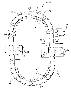
hIG. 1 is a top overhead view of a first layout of an
overall conveyor system 10 according to the present invention,
which is essentially an endless conveyor having two "semi-
circle" portions and two straight-line portions.
FIG. 2 is a top plan view of a second layout of an
overall conveyor system 10 according to the present invention
in including a serpentine conveying path l9.
FIG. 3 is a side partial cut away view illustrating the
interaction of an edge drive pulley with the reinforced edge of
a base of a "tilt tray" package conveying segment.
FIG. ~ is a top plan view of a straight section of a
conveyor system 10 according t o the present invention
including a plurality of tilt tray package conveying segments
50 and a plurality c>f necked portions 14.
FIG. .S is a. toga plan view of a curved section of a
conveyor system a.ccordislg to the present invention including; a
plurality of tilt tray package conveying segments 50,
illustrating the interaction of the cun~ed section with edge
drive pulleys positionE:d on the "inside" of the curve along
which the seg;menta are traveling.
FIG. G is a cross-sectional view of a tilt tray package
conveying segment 50, illustrating the interaction of same with
air supply ports 2~ asxd with an adjacent edge drive pulley 30.
I~IG. 7 is a view similar to that of Fig. 6, except that one
of the two bellows is shown expanded due to the introduction
of air therein.
FIG. 8 is an pictorial view oil an isolated section of
cogged belt 70 according to the present invention.
FIG. 9 is a sidf; plan view of an isolated section of
cogged belt 70 according to the present invention in
engagement with a built-up edge portion of a conveying
segment generally denoted as 78.
CA 02276482 2003-06-09
6
FIG. 10 is a top plan view of an edge drive assembly 60 according to the
present
invention, in edge engagement with a portion of a conveyor according to the
present invention.
FIG. 11 is a side elevational view of a "'push plate" package conveying
segment,
shown in its retracted mode.
FIG. 12 is a side elevational 'view of the "push plate" package conveying
segment
100 of Fig. 11, shown in it extended m«de.
FIG. 13 is a top elevational view of the "push plate" package conveying
segment 100
of Fig. 11, shown in its retracted made.
FIG. 14 is a top elevaticfnal view of the "push plate" package conveying
segment of
Fig. 11, shown in its extended mcade.
FIG 15. is a top plan view of an isolated length of a conveyor system
according to
the present invention., including a "'push plate" package conveying segment of
Fig. 1 l, showing
different discharge capabilities of a dual--bellows configuration.
FIG. 16 is a cross sectional view of the configuration shown in Fig. 15,
additionally
showing an air inlet.
FIG. 17 is a top plan view of a conveyor section including a plurality of push
plate
conveying segments attached thereto, suci~ that single side discharge is
provided.
FIG. 18 is a side elevational view of a conveyor system according to the
present
invention, which includes the use ol~ drum rollers to support the conveyor.
FIG. 19 is a top plan view of a conveyer section including a plurality of push
plate
package conveying segments attached thereto, such that dual side discharge is
provided.
Detailed Description
Reference is now made iii more detail to the drawings, in which like numerals
refer
CA 02276482 2003-06-09
7
to like parts throughout the several views.
General Discussion
General operation of thin conveyor apparatus 10 according to the present
invention
is as follows. Referring first to Iaig. I, the conveyor apparatus 10 according
to the present
invention includes a plurality of c«nveying segments 1 I which are attached
together by flexible
necked portions 14 (see Fig. 4), which allow the conveying segments 11 to
pivot sidewardly
relative to each other. This relative pivoting capability allows the conveying
segments 11 to
be moved along a curved or even serpentine hatl~ such as shown as 19 in Fig.
2. The
conveying segments I 1 are configured to support (either directly or
indirectly as discussed in
detail below) packages 20 or other items, thus allowing the conveyor system 10
to likewise
move the packages along a curved c>r serpentine path and eject them therefrom.
The packal;e conveying segments generally denoted as 11 of the serpentinf:
conveyor
system 10 can take different particular configurations. In the case of Figs. 3
- 7, a tilt tray
package conveying segment 50 including trays such as 'i I supported by
vertical bellows
members 54 can be used such that a package placed atop the tray slides off at
least partly under
the influence of gravity upon selective tilting c>f the tray by the bellows.
Figs. 11 -- 19 illustrate another type of package conveying segment, a "push
plate"
conveying segment 100, in which two or more horizontally-acting bellows
members are
attached relative to the top surfac,: of the base 102 of the push plate
conveying sel;ment 100,
to provide a pushing function to a. packag a situated atop the top surface of
the base: 102, such
that it slides off the base 102.
CA 02276482 2003-06-09
WO 98!30476 PCT/US98I00107 ,
8
The conveyor system 10 can also include the use of side-
urging pulleys 30 (sea Figs. 1, 3 and 5) or a belt 70 (see Figs.
8-10), to grip and drive the discrete side edges of the package
conveying segments. As these side edges 13 are spaced apart
by notches, and if~ pulleys 30 are used, the position of the
pulleys can be on the "inside" of the path curve, where the
notches tend to be substantially or completely closed. If a belt
is used, it is not as critical that the notches be closed. In fact,
the belt can be used. on th.e inside of the path curve, or can also
be used along a straight portion of the curve.
It may be well understood that this serpentine capability
provides a marked advantage for conveyor system designers,
as it does not restrict them to the use of straight conveying
paths. It also allows for the use of a "carousel" - type
conveying system which can provide a continuous support loop
for the support and conveyance of packages, effectively
allowing for packages to remain on the conveyor over more
than one of its proccas cycles. This is to be distinguished from
"over-under" conveying systems in which the conveyor is
facing upwardly (and can be used) half the time, but is facing
downwardly (and cannot be used) the other half of the time.
Typically in such a configuration, drive and idler rollers
having substantially horizontal axis are used to support and
drive the; conveyor.
More Particular Discussion
A. The General Layouts (Figs. 1-~?)
As shown in Fig. l, the conveyor apparatus 10
according to the present invention includes a plurality of
conveying segments 1 l which are attached together by flexible
necked portions 14 (;see Fig. 4), which allow the conveying
segments 11 to pivot sidewardly relative to each other. This
relative pivoting capability allows the conveying segments 1:
to be moved along an oval-shaped path having curves and
straight portions as shown in Fig. 1, and also allows them to
CA 02276482 2003-06-09
9
move along a serpentine path shown as 19 in Fig. 2. The conveying segments 11
are
configured to support (either directly or indirectly as discussed in further
detail below) packages
20 or other items, thus allowing the conveyor system 10 to likewise move the
packages along
a curved or serpentine path. In the: preferred embodiment, the conveying
segments 11 and the
flexible necked portions 14 are al.i part of the same flexible conveyor belt,
although other
separate configurations are also contemplated.
As shown in Fig. 1, the lath of the package conveying segments can be oval-
shaped
and pass along side various destination chutes such as 2(~. Within a loading
station 25,
packages may be placed upon the package conveying segments 1 l, from loading
positions 25P.
'these loading positions 251? can be occupied by human operators hand-placing
packages atop
the package conveying segments, car could alternately be mechanical means as
known in the art.
The flexible necked portions are an important part of the present invention.
As
shown in Fig. 1, the package conveying segments 1 1 may travel along a path
which includes
straight portions as well as curves, requiring the package conveying segments
11 to pivot
sidewardly relatively to each other when naalong the transition from the
curved portion to the
straight portion, or vi~~e versa. The notches 15 present in the flexible neck
portions 14 provide
clearance to facilitate such sideward filex ing.
Reference is now also r~uade to Figs. 4 and 5, which are more detailed similar
top
plan views of the conveyor according to the present invention, illustrating a
particular type of
package conveying sc;gment 50 used with the flexible necked portions 14.
Fig. 4 shows a '"straight-line" length of the conveyor 10,
that is, the shape the conveyor take:, when passing along a
straight line path. In such a configuration, the notches 15 in
CA 02276482 2003-06-09
WO 98130476 PGT/LTS98l00107
the flexible necked portions 14 are effectively the same shape
regardless of which side they are on.
Fig. 5 illustrates the shape of the conveyor length as it
passes around a curve. As may be seen in Fig. 5, the "inside"
notches in the conveyor belt tend to be almost or completely
closed, thus accommodating the pivoting action. Similarly, the
"outside" notches tend to be more open, with flexing occurring
along the flexible necked portion 14.
,4s may well be understand, the flexible necked portions
of the conveyor system can undergo a high degree of stress
over their lifetimes, due to the fact that they are being
repeatedly flexed while; making turn transitions, as well as the
fact that their reduced configuratians require their narrowest
cross section to not only flex but to carry a significant load.
Therefore, it has l7een deemed preferable to include additional
reinforcement in the form of 1EVLAR or steel
reinforcements as shaven in Fig. 6. As shown in Fig. 6, an
elongate reinforcement: strip 17 can be attached (by gluing or
other suitable meaans) to one side of the notched but otherwise
conventional conveyor belt, such that the reinforcement strip
provides additional reinforcement at. the center of the b~°lt,
which will be the portion that will be doing the flexing as well
as carrying any tensile; or compressive load. Fig. 6 likewise
illustrates an ou~:er edge restraint 5$, and a powered edge
pulley 30, which will be discussed later in further detail.
The Edge Gripping Pulleys(Figs 3, S-7)
As noted above, and referring generally to Figs. 3, 5-7,
the conveyor system 10 can include the use of edge drive
pulleys 30, to grip the. discrete side edges of the package
conveying segments to cause the conveyor to move along its
path. As these side edges 7 3 are spaced apart by notches 15,
and if pulleys 30 are used, the position of the pulleys can be: ~n
the "inside" of dne path curve, where the notches tend to be
substantially or cc:>mplf;tely closed. This is advantageous in that
CA 02276482 2003-06-09
WO 98/30476 PCT/US98/00107
11
the partial or complete closing of the gaps provided by the
notches can providf; a substantially or completely continuous
edge which is "seen" by the edge drive pulleys 30. In the
configuration shown in Figs. 1 and S, the notches arc:
completely closed, such that a continuous edge is "seen" by thc:
driving pulleys. In the configuration shown in Fig. 10, the
notches are not completely closed.
In one embodiment of the present invention such as
shown in Fig. 1, thca side edge of the conveying segments 111
are not straight, instead they are slightly "cupped" inwardly
such that a semicircle of substantially constant radius is defined
by the inner edges of the conveying segments as they go
around each half turn. This provides a substantially consistent
edge for the pulleys 30 to drive. However, the pulleys 30 can
be spring-loaded to accommodate slight variations due to
tolerances and wear..
In one preferred embodiment, the notches define a seven
degree (J~) angle, flue reinforcement strip is approximately 1.'i
inches in width, and the. lateral spacing of the peaks of the
notches is likewise 1.5 inches. The notches are sixteen (16)
inches on center and a ~ 0 foot tum radius is accommodated
with full closure of flue inside notches. The reinforcement
strip is a conventional steel or KEVLAR reinforced belt.
In the configuration shown in Fig. l, these edge drive
pulleys :30 are located inside the conveying path, along the
inside edge of the pelt path as shown in Fig.l. However, in
reference to Fig. 2, it rna.y be seen that the edge drive pulleys
30 can also be located outside of the conveyor path, but at the
same time being oru the inside of a particular conveyor path
curve.
In Figs. 5, 6, and 'l, an edge restraint 58 is provided on
the outside of the curved path, in order to laterally restrain
movement of the conveying segments as they are urged by the
edge pulleys. The package conveying segments are therefore
captured between tile edge pulleys 30 and the outer restraint
CA 02276482 2003-06-09
12
58 and moved therebetween by the force of the edge pulleys 30. However, it may
of course
be understood that outer edge restraints such as S8 could be used at many
different locations
along the conveyor belt path, not only to provide the above-referenced
capturing feature, but
also as shown in Fig. 11 to provide a retaining function which may be needed
to counter a
sideward force imparted to the belt during a dynamic hushing function
discussed later in this
application. Finally, edge restraints such as 58 can be used along belt
portions that may need
some guidance for other reasons. hor example, it could be necessary to use two
cooperating,
inwardly-directed edge restraints 58 to encourage belt alignment at a
particular location along
its path.
T he Edge Drive Belt (Figs. 8 - IO,J
As noted ahove, gripping; and urging of the notched sides of the conveyor may
be
provided by edge drive pulleys 30 as discussed above, or alternately by use of
a continuous
edge driving togged r~elt 70, showo7 in Figs. 8 -- 10.
Fig. 8 illustrates an isolated cut--away section of a togged belt 70. The
togged belt
70 includes a togged portion 72 and a channel portion 7Ei. 'The togged portion
72 and channel
portion 76 are joined together in a laminated fashion. The togged portion 72
is composed of
conventional polyester belt material in the preferred embodiment and the
channel portion 76
is composed of urethane.
The channel portion 76 is configured to matingly engage built-up edge segments
78
(see Fig. 9), which arc attached to the belt edge of the conveyor segments 11.
In the preferred
embodiment, the discrete built-up edge segments 78 are composed of urethane.
Reference is now made t~c~ Fig. I(), which illustrates the use of a plurality
of pulleys
to drive an endless togged belt 70. The c:ogged belt 70 is driven by a togged
belt drive pulley
66 and idler pulleys 64 situated on the inside edge of the togged belt path
maintain the togged
CA 02276482 2003-06-09
13
belt in its appropriate path. A tail pulley 61 and retainer pulley GS are
likewise shown in
contact with the belt 70.
'the pulleys 62, 64, 65 and 66 are oriented such that their rotational axes
are all
substantially vertical, such that the endless cogged bolt 70 lies in a plane
which is substantially
parallel to the plane of the conveyor supporting surfaces. The drive pulley
62, the idler pulleys
64 and the tail pulley 62 lie, in the view shown in Fig. 10, along a generally
curved path
adjacent to the side of the path of the package conveying segments l;enerally
noted as 11.
As noted above, the endless channel 76c defined by the endless channelled
portion
76 of the endless cogged belt is c:onligured to matingly accept a plurality of
built-up edge
segments 78 attached to a correspc7nding plurality of package conveying
segments 1 1. In the
configuration shown in Figs. 8 an<.l 9, the channels 76C'. are defined by
three wall surfaces, a
central wall surface and two outwardly tapering wall surfaces. "these three
surfaces are
configured to frictionally engage a corresponding three surfaces located along
the marginal
outside edge of the built-up edge segment 78. 'this frictional engagement is
sufficient to cause
conveyor segments such as 11 to loe moved along their path, upon the driving
of the cogged
belt 70 by, for example, the drive pulley 62.
As noted above, the endless c.crgged belt 70 is configured to engage and drive
more
than one package conveying segment 1 1 at one time. In the configuration shown
in Fig. 10,
the endless belt 70 engages at least five (5) separate built-up edges of five
(5) package
conveying segments z I . In the configuration shown in Fig. 10, it may also be
noted that the
"inside" notches discussed above .are not completely closed. However, the belt
70 tends to
"bridge" these notchea.
It should be: understood that the endless cogged belt does not have to be on
the inside
of the conveyor path curve as shown in Fig. L0. Instead the belt 70 could be
adjacent to the
CA 02276482 2003-06-09
14
conveyor segments 11 while they travel un a straight path segment, or the belt
70 could even
be on the outside of the curve.
t should also be noted that it is also c<~ntemplated under the present
invf:ntion that
the endless cogged belt be in direct coIltact with the side edge of a conveyor
belt, that is, no
built-up edge would be used.
Vertical Bellows (Figs. 3, t - 7)
As noted above, the package conveying segments generally denoted as 11 of the
serpentine conveyor system 10 can take different particular configurations.
One such
configuration is shown in Figs. a ~-- ?. These Figures show a tilt tray
package conveying
segment 50 including tiltable trays such as 51 supported by vertical bellows
members 54, which
can be used such that a package. placed atop the tray slides off" at least
partly under the
influence of gravity upon tilting of the tray by the bellows. The conveyor
segment base 52
(which in one preferred embodime"nt is of conventional flexible conveyc»- belt
material) defines
bellows ports 56, which facilitate air passage therethrough to corresponding
bellows 54 to cause
their inflation as discussed in detain below. Such a port S6 allows for air to
pass therethrough,
such that air blown through the port under a relatively low pressure
facilitates inflation and
expansion of its associated bellow member, causing the tray to be moved
upwardly. Assuming
that only one bellows is inflated, this causes the tray 51 to tilt, thus
allowing for sliding
movement of a package from atop the tray 51 (see Fig;. 7).
Figs. 6 and 7 both illustrate similar views, with Fig. 6 illustrating the
configuration
before inflation of one of the bell«ws S4 and Fig. 7 illustrating one c~f the
bellows inflated. Fig.
7 illustrates the opening of one of the air valves 24, allowing air to flow
into a corresponding
one of the two bellows 54. 'This causes the associated side of the tray 51 to
be raised
CA 02276482 2003-06-09
higher than the other side of the tray, causing the package to slide from the
inclined tray
surface. In the configuration shown in Fig. 7, the. package slides off the
side having the outer
edge restraint 58 described above.
Referring momentarily to Figs. 4 and .5, the ports 56 which supply the air to
their
associated bellows may be seen to iae tear--shaped. The reason for this is to
allow a round port
thereunder to supply air at a controlled l;radual manner. The "tail" portion
of the 'tear is the
first to encounter the round hole thereunder.
Horizontal Bellows (Figs. l1 - 19i
Another particular type of package conveying segment generally denoted as 11
in Fig.
1 can be a "push plate" conveying segment shown as 100 in Figs. 11 - 19. In
this
embodiment, two or more horizontally--acting bellows members are attached
relative to the top
surface of the base 102 of the push plate conveying segment 100, to provide a
pushing function
to a package situated atop the top surface of the base 102, such that it is
pushed off the
conveying segment base 102.
Referring now particularly to f~ ig. I 1, the configuration 100 includes a
base 102, a
chamber housing 103, bellows members l06 and a push plate 104. The air chamber
housing
103 of the push plate conveying sf~gment l00 is attached to the upper surface
of the base 102
and is configured so it fits under tif~e evdg;o restraint 58. 1'he air chamber
housing 103 defines
an interior air chamber 105 which is supplied air through a chamber inlet port
103 and itself
supplies air to two chamber outlet ports 107. Each of tine two chamber outlet
ports 107
supplies air from the chamber 105 t:o a~ corresponding one of the two
horizontally-oriented
members 106. In one preferred embodiment, the base 102 is composed of
flexible; conveyor
belt material.
'The bellows members I t)6 operate such that they extend along their lengths
upon the
CA 02276482 2003-06-09
16
introduction or air, such that their two ends are separated along the width of
the package
conveying segment 100. The bellows members 106 are side--by-side in a parallel
relationship
and each has one end attached to the air chamber housing 103 and the other
attached to the
push plate 104. Upon the energizerneru of the bellows members 106 from their
retracted
positions shown in Figs. I 1 and l:> to their extended positions shown in
Figs. 12 and 14, the
push plate 104 is itself pushed substantially across the width of the base 102
of the push plate
conveying segment 100. Should a packa;e be positioned on the base 102 beside
the push plate
104, it is discharged from the base as shown in Fig. 16 by the bellows members
106.
Energizement of the bellows member is prcnvided by opening a valve such as 116
from its
position shown in Fig. I 1 to its position .shown in Fig. 12.
,~S SHOWII Ill Figs. l3 and 14, the conveying segment 100 includes a
retracting cable
110, which is extended and contracted a~~-om a retracting cable housing 112.
The retracting
cable housing 112 is attached relative to tlve air chamber Housing 103 and
thus the base 102.
The retracting cable 110 is mounted within the retracting cable housing 1 12,
such that a tensile
force is imparted on the cable 110 ,such that a pull is ever present on the
push plate which tends
to retract it from its extended position of Figs. 1 l and 14 to its retracted
position of Figs. I 1
and 13. The force imparted by the retracting cable 110 is sufficient to
retract the bellows only
when the bellows are not energized.
Figs. 13 and 14 are toh~ plan views of a configuration 100, illustrating the
"dual"
feature possible in such a construction. I~c~wever, it should be understood
that one, two, or
even more bellows may be used in a particular construction. The port 106 is
shown in an
elongated configuration in Figs. 13 and l4, which is to allow air to enter the
air chamber 105
over a longer period of time than if' the port was simply round as the inlet
port 10:3 is wide.
CA 02276482 2003-06-09
17
Fig. 15 illustrates the capability of the conveyor according to the present
invention
to initiate either angled or straight, ( °'square") discharge, by
allowing the bellows to extend in
a uniform manner, as in the rightmost segment, or in a non-uniform manner, at
least through
a portion of their stroke, as shown in the middle segment. This could be done
by controlling
air flow as needed.
Fig. 17 provides single side discharge of the packages. Fig. 19 shows dual-
side
discharge of the packages.
As may be understood, the somewhat rigid form of the air chambers which are
attached atop the otherwise flexible package conveying segments 1 I of Fig. 17
could make
"over-under" conveyor set-ups using cylindrical conveyor drive and idler
rollers impractical.
Therefore, Fig. 1 ~> shows the use of a h~:xagor~ally-shaped drive roller 115,
which
accommodates such over---under ccanfigurations.
As may be understood, such an aver-under configuration would not have to use
the
notches as discussed above, instead a conventional, unnotched, conveyor belt
could also be used
to support assemblies such as 100 thereon.
Fig. 19 shows an als:ernate configuration which may be used with the present
invention. In this configuration, instead of being supported by what is
essentially a notched
conventional flexible conveyor belt, solid platforms can be used to support
the bellows
assemblies and to provide the hackag;e supporting surfaces within each package
supporting
segment l 1.
Interconnecting the ri,~id platforms are flexible intercc:mnectors 111, which
can be
such as those described in my Canadian co-pending application No.
2,271,073 filed January 20, 1998 und~:r the title "Automated Lateral
Translation Conveyor" (which may be referred to for further details), which
are essentially rubber intercc>nnectors each of which include two opposing
male
CA 02276482 2003-06-09
WO 98130476 PCT/US98/00107
18
flanges which fit into female "notches" defined in the edge
ends of the platforms and link two adjacent platforms together.
The interconnectors can also include an elongate tooth running
its length, which can be driven by a slot defined by a drive
member such as a roller, such that the platforms are isolated
from the drive means by the flexible connectors, while still
being driven by the drive means through the connectors. This
is suitable for an "over-under" configuration as described
above.
Alternate Configurations
If so desired, the reinforcement strip 17 could be located
underneath the belt instead of atop it as shown in Fig. 6. In
such a configuration, a flat supporting surface would not be
suitable for supporting the conveyor, but an upwardly-directed
slot (not shown) could be provided to accommodate the strip.
In fact, such a slot/strip combination could be used to
accommodate lateral side forces on the belt.
It should be noted that one of the two ports of Fig. 13
can be a different size, to allow the side of the pusher plate
with the smaller hole to "lay" behind the side corresponding to
the larger hole. 'This could also be accomplished by providing
an insert to reduce the size of the hole.
It should also be understood that the air chamber 105
could be of a two-part configuration (not shown), with two
inlet holes instead of one inlet hole, and two air chambers
(corresponding to each bellows) to allow for different
selectable dynamic actions of the corresponding bellows.
It should also be understood that the package conveying
segments 11 shown in Fig. 1 could have no package discharge
capabilities; the segments could simply be bare conveyor belt
segments which simply support packages thereon, and rely
upon outside means for receipt and discharge.
Construction Maeerial s
CA 02276482 2003-06-09
WO 98130476 PCT/US98/00107
19
As noted above, under one embodiment of the present
invention, an endless polyester flexible belt can be used to
comprise the conveying segments 11 and the flexible necked
portions 14. In fact, under such a configuration the
construction could be thought of as a flexible belt which is
"notched" along its longitudinal sides to provide the above-
referenced flexing features. While on the subject, it should be
noted that the fle:~cible nature of such a belt could result in
some hexing within the package conveying segments 11
themselves, although it is contemplated that most of the flexing
will be in the location between the notches 15.
The bellows can be made of conventional woven
polyester. 'hhe ai~~ chamber 1U3 (in Fig. 11 for example) can
be composed of plastic, fiberglass, urethane, and can be
extnlded and capped at its ends.
Conclusion
While this invention has been described in specific detail
with reference to the disclosed embodiments, it will be
understood that r:nany variations and modifications may be
effected within the spirit and scope of the invention as
described in the appended claims.