Language selection

Search

Patent 2276776 Summary

Third-party information liability

Some of the information on this Web page has been provided by external sources. The Government of Canada is not responsible for the accuracy, reliability or currency of the information supplied by external sources. Users wishing to rely upon this information should consult directly with the source of the information. Content provided by external sources is not subject to official languages, privacy and accessibility requirements.

Claims and Abstract availability

Any discrepancies in the text and image of the Claims and Abstract are due to differing posting times. Text of the Claims and Abstract are posted:

  • At the time the application is open to public inspection;
  • At the time of issue of the patent (grant).
(12) Patent: (11) CA 2276776
(54) English Title: MULTI-STAGE FIBER AMPLIFIER WITH FLATTENED GAIN CURVES
(54) French Title: AMPLIFICATEUR A FIBRES OPTIQUES A PLUSIEURS ETAGES ET A COURBES DE GAIN LISSEES
Status: Expired and beyond the Period of Reversal
Bibliographic Data
(51) International Patent Classification (IPC):
  • G02F 01/39 (2006.01)
  • H01S 03/067 (2006.01)
  • H01S 03/10 (2006.01)
  • H01S 03/30 (2006.01)
(72) Inventors :
  • PARK, NAM KYOO (Republic of Korea)
  • LEE, JU HAN (Republic of Korea)
(73) Owners :
  • SAMSUNG ELECTRONICS CO., LTD.
(71) Applicants :
  • SAMSUNG ELECTRONICS CO., LTD. (Republic of Korea)
(74) Agent: SMART & BIGGAR LP
(74) Associate agent:
(45) Issued: 2003-02-04
(86) PCT Filing Date: 1998-09-28
(87) Open to Public Inspection: 1999-04-15
Examination requested: 1999-07-05
Availability of licence: N/A
Dedicated to the Public: N/A
(25) Language of filing: English

Patent Cooperation Treaty (PCT): Yes
(86) PCT Filing Number: PCT/KR1998/000298
(87) International Publication Number: KR1998000298
(85) National Entry: 1999-07-05

(30) Application Priority Data:
Application No. Country/Territory Date
51051/1997 (Republic of Korea) 1997-10-02

Abstracts

English Abstract


This invention provides noise figure reduction and gain flatness enhancement
of a fiber amplifier using multi-stage equalizing filter. According to the
invention, noise figure can be lowered by splitting equalizing filter into
multiple stage filtering conditions.


French Abstract

L'invention porte sur la réduction du facteur de bruit et sur l'amélioration du lissage du gain d'un amplificateur à fibres optiques au moyen d'un filtre d'égalisation à plusieurs étages. Selon cette invention, il est possible de réduire le facteur de bruit en réalisant le filtrage d'égalisation en plusieurs niveaux de filtrage.

Claims

Note: Claims are shown in the official language in which they were submitted.

CLAIMS:
1. A multi-stage optical fiber amplifier, comprising:
at least three fiber amplifier stages, each of
which includes a length of doped optical fiber, the stages
being connected in series for the sequential amplification
of optical signals provided to the first amplifier stage;
means for providing pumped radiation into said
amplifier stages so as to support laser amplification
therein; and
at least two long-period fiber gratings, each of
which is located between each pair of said amplifier stages.
2. The multi-stage optical fiber amplifier of claim
1, wherein said optical fiber is doped with rare earth
element.
3. The multi-stage optical fiber amplifier of claim
2, wherein said rare earth element is erbium.
7

Description

Note: Descriptions are shown in the official language in which they were submitted.


CA 02276776 1999-07-OS
WO 991I8476 PCT/KR98/00298
MULTI-STAGE FIBER AMPLIFIER
WITH FLATTENED GAIN CURVES
TEC~INICAL FIELD
The present invention relates to a fiber amplifier, more particularly
to a mufti-stage erbium doped fiber amplifier with flattened gain curves
and reduced noise figure when incorporating a gain flatness filter for
WDM applications.
BACKGROUND ART
to It has long been recognized that fiber amplifiers are an attractive
alternative for amplifying optical signals. For example, fiber amplifiers
have been proposed for the use as a booster amplifier to increase the output
power from a telecommunication optical transmitter or as a
telecommunication repeater to amplify optical signals without converting
is the optical signals into electrical signals.
Especially, the advent of the Erbium Doped Fiber Amplifier
(EDFA) has had a profound impact on the design, manufacturing and
performance of optical communication systems. Its low noise, high optical
power, high gain, linearity, wide bandwidth, wavelength transparency,
2o polarization independence and fiber compatibility have revolutionized
optical communications by effectively removing the transmission and
splitting loss barriers. As a result today, long haul terrestrial and
transoceanic fiber communications, as well as local and wide area
networks, have become realities.
as However, the flatness of the EDFA pass-band becomes a critical
issue in Wavelength Division Multiplexing (WDM) systems with cascaded
i

CA 02276776 2002-03-13
75998-16
amplifiers. The amplifier gain is not exactly same at each wavelength.
For example, in the case of 0.8nm channel-width, one EDFA can
simultaneously amplify optical signals from approximately SO WDM
channels. However, if several EDFAs are connected in series for long-
s distance transmission, the gain curve flatness of overall amplification gets
worse and show the problem of insufficient amplification at the edge of
amplification peak. Even small variations in gain between channels in a
stage can therefore cause large variations in the power difference between
channels at the output of the chain, lowering the performance of the entire
io system.
In general, the performance of an optical amplifier is determined by
its design parameters such as gain, output power and noise figure. Noise
figure is defined as an amplifier output signal to noise ratio, scaled by the
signal to noise ratio at the input port of the optical amplifier. When optical
is amplifiers are used as a telecommunication repeater, high power and low
noise become critical parameters in increasing the distance between
adjacent repeaters.
The importance of a wavelength-independent (flat) gain in EDFAs
is evidently manifested by the large current research effort in the freld
Zo since it is directly related to the transmission capacity of dense WDM
systems. Fluoride based EDFAs and Tellurite based EDFAs have been
demonstrated to achieve the wider flattened bandwidth. Such a research
result can be found in M. Yamada et al., "Low-noise and gain-flattened
fluoride-based Er3+-doped fiber amplifier pumped by 0.97um laser diode,"
Zs Electron. Lett., vo1.33, no.9, p.809, 1997, and in A. Mori et al., "l.Sum
broadband amplification by tellurite-based EDFAs," optical Fiber
Communication conference and exhibit, Dallas, Tx, U.S.A.
February 16-21, 1997.
2

CA 02276776 2002-03-13
75998-16
It was also shown that a long-period fiber-grating filter
could be implemented to obtain the flattened bandwidth
beyond 40nm. Even though, discreet and careful design of
the EDFA is required because the filter insertion in the mid
stage of the EDFA could produce a noise figure penalty, as
is described in P.F. Wysocki et al., "Erbium-doped fiber
amplifier flattened beyond 40nm using long-period grating",
Optical Fiber Communication conference and exhibit, Dallas,
Tx, U.S.A. February 16-21, 1997.
The inventors therefore analytically derived the
dependence of the noise figure on filter transmission
through a numerical simulation.
In accordance with the present invention, there is
provided a multi-stage optical fiber amplifier, comprising:
at least three fiber amplifier stages, each of which
includes a length of doped optical fiber, the stages being
connected in series for the sequential amplification of
optical signals provided to the first amplifier stage; means
for providing pumped radiation into said amplifier stages so
as to support laser amplification therein; and at least two
long-period fiber gratings, each of which is located between
each pair of said amplifier stages.
FIG. 1 schematically shows the configuration of an
EDFA comprising a single-stage equalizing filter which was
used for the simulation.
Referring to FIG. 1, a single stage filter 10 is
located at the 1/3 position of total fiber amplifier length
L. A long-period fiber grating (LPFG) is used as the single
stage filter 10. The amplifier was modeled as a
homogeneously broadened three level system as was described
3

CA 02276776 2002-03-13
75998-16
in C.R. Giles et al., "Propagation of signal and noise in
concatenated EDFAs", J. Lightwave Technol., vol.9, no.2,
p.147, 1991. The spectral range of 120nm between 1480nm and
1600nm was used with the spectral grid of O.lnm to cover the
pump wavelength of 1480nm. The fiber amplifier was assumed
to a silica based aluminum co-doped fiber and then the
absorption cross section was taken from the value disclosed
in N. Kagi et. al., "Temperature dependence of the gain in
erbium-doped fibers", IEEE J. Lightwave Technol., vol.9,
no.2, p.261, 1991. The emission cross section was
calculated from McCumber theory.
FIG. 2 shows the detailed spectral profile of the
LPFGs in a single-
3a

CA 02276776 1999-07-OS
WO 99/18476 PCT/KR98/00298
stage equalizing filter of FIG. 1.
FIG. 3 shows the output spectrum of the EDFA described in FIG. 1.
41 input signals of 0.8nm spacing between 1531nm and 1563nm were used
to observe gain flatness and noise figure, at -20dBm input power for each
s channel. The achieved mufti-channel gain flatness was within 0.4dB over
32nm spectral range, and signal gain per channel was around 23dB. Even
though this configuration meets good gain flatness, the amplified
spontaneous emission (ASE) in this amplifier is not regulated due to high
noise figure in short wavelength regime, making the application of this
io amplifier to the noise sensitive application such as long distance link
difficult.
DISCLOSURE OF THE INVENTION
Therefore, it is an object of the present invention to provide a high
performance flat-gain fiber amplifier.
It is another object of the present invention to provide a fiber
amplifier with lower noise figure.
In order to accomplish the aforementioned objects, the present
invention provides a mufti-stage optical fiber amplifier that achieves ultra-
flat gain using mufti-stage equalizing filters. The fiber amplifier of the
Zo present invention comprises at least three fiber amplifier stages, each of
which includes a length of doped optical fiber. The amplifier stages are
connected in series for the sequential amplification of optical signals
provided to the first amplifier stage. One of the amplifier stages is
provided with pumped radiation so as to support laser amplification therein.
Zs The fiber amplifier also includes at least two equalizing filters, each of
which is located between each pair of said amplifier stages.
a

CA 02276776 1999-07-OS
WO 99/18476 PCT/KR98/00298
Since the noise figure is inversely proportional to the first-stage
equalizing filter transmission, noise figure can be lowered by splitting
equalizing filter into multiple stage filtering conditions.
Since the output power of the amplifier is inversely proportional to
s the end-stage equalizing filter transmission, careful adjustment of the
transmission spectra of each filter is necessary.
BRIEF DESCRIPTION OF THE DRAWINGS
The detailed description particularly refers to the accompanying
drawings in which:
to FIG. 1 schematically shows the configuration of an EDFA
comprising a single-stage equalizing filter which was used for the
simulation;
FIG. 2 shows the detailed spectral profile of the LPFGs in a single-
stage equalizing filter of FIG. 1;
is FIG. 3 shows the output spectrum of the EDFA described in FIG.
1;
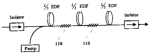
FIG. 4 schematically shows the configuration of the EDFA
according to an embodiment of the present invention;
FIG. 5 shows the detailed spectral profile of the LPFGs in double-
Zo stage equalizing filters of FIG. 4;
FIG. 6 shows the output spectrum of the EDFA described in FIG.
4;
FIG. 7 shows calculated noise figures of EDFAs with two kinds of
equalizing filters.
2s BEST MODE FOR CARRYING OUT THE INVENTION
Referring to FIG. 4, two LPFGs 110 are located at the 1/3 and 2/3
s

CA 02276776 1999-07-OS
WO 99/18476 PCT/KR98/00298
positions of total fiber amplifier length L, respectively. For the double
stage filter configuration comprising two LPFGs, each gain flattening filter
is square rooted one of the total filter transmission. The fiber amplifier
employed a silica-based aluminum co-doped EDF(erbium doped fiber).
s The EDF is pumped at 1480nm by a semiconductor laser that is used as an
optical pump.
Referring to FIG. 5, the LPFGs show a notch filter characteristic.
The absorption peak positions are the same as those of FIG. 3. However,
the depth profile is different from each other.
io Referring to FIG. 6 and FIG. 3, the output signal power and ASE
power of the EDFA employing a single stage filter is stronger than those of
the EDFA employing a double stage filter by ldB. However, the ASE
power spectrum in a single stage filter is less regulated, compared with that
in a double stage filter, implying higher noise figure penalty.
is Calculated noise figures of EDFAs with two kinds of equalizing
filters are plotted in FIG. 7. Referring to FIG. 7, maximum noise figure
difference of 0.7dB is found at the wavelength of 1535nm where filter
transmission is a minimum. Not much difference in noise figure is
observed at 1543nm where the filter transmission is maximum.
ao From these results, it is concluded that the EDFA with a double
stage equalizing filter is superior to that with a single stage filter in
terms
of noise figure, though using a mufti-stage equalizing filter decreases the
EDFA gain a little.
6

Representative Drawing
A single figure which represents the drawing illustrating the invention.
Administrative Status

2024-08-01:As part of the Next Generation Patents (NGP) transition, the Canadian Patents Database (CPD) now contains a more detailed Event History, which replicates the Event Log of our new back-office solution.

Please note that "Inactive:" events refers to events no longer in use in our new back-office solution.

For a clearer understanding of the status of the application/patent presented on this page, the site Disclaimer , as well as the definitions for Patent , Event History , Maintenance Fee  and Payment History  should be consulted.

Event History

Description Date
Inactive: IPC expired 2013-01-01
Time Limit for Reversal Expired 2008-09-29
Letter Sent 2007-09-28
Inactive: IPC from MCD 2006-03-12
Grant by Issuance 2003-02-04
Inactive: Cover page published 2003-02-03
Pre-grant 2002-11-13
Inactive: Final fee received 2002-11-13
Notice of Allowance is Issued 2002-05-23
Letter Sent 2002-05-23
Notice of Allowance is Issued 2002-05-23
Inactive: Approved for allowance (AFA) 2002-05-15
Amendment Received - Voluntary Amendment 2002-03-13
Inactive: S.30(2) Rules - Examiner requisition 2001-11-13
Inactive: Cover page published 1999-09-30
Inactive: First IPC assigned 1999-08-26
Inactive: IPC assigned 1999-08-26
Inactive: Acknowledgment of national entry - RFE 1999-08-12
Letter Sent 1999-08-12
Application Received - PCT 1999-08-11
All Requirements for Examination Determined Compliant 1999-07-05
Request for Examination Requirements Determined Compliant 1999-07-05
Application Published (Open to Public Inspection) 1999-04-15

Abandonment History

There is no abandonment history.

Maintenance Fee

The last payment was received on 2002-08-22

Note : If the full payment has not been received on or before the date indicated, a further fee may be required which may be one of the following

  • the reinstatement fee;
  • the late payment fee; or
  • additional fee to reverse deemed expiry.

Patent fees are adjusted on the 1st of January every year. The amounts above are the current amounts if received by December 31 of the current year.
Please refer to the CIPO Patent Fees web page to see all current fee amounts.

Owners on Record

Note: Records showing the ownership history in alphabetical order.

Current Owners on Record
SAMSUNG ELECTRONICS CO., LTD.
Past Owners on Record
JU HAN LEE
NAM KYOO PARK
Past Owners that do not appear in the "Owners on Record" listing will appear in other documentation within the application.
Documents

To view selected files, please enter reCAPTCHA code :


To view images, click a link in the Document Description column. To download the documents, select one or more checkboxes in the first column and then click the "Download Selected in PDF format (Zip Archive)" or the "Download Selected as Single PDF" button.

List of published and non-published patent-specific documents on the CPD .

If you have any difficulty accessing content, you can call the Client Service Centre at 1-866-997-1936 or send them an e-mail at CIPO Client Service Centre.


Document
Description 
Date
(yyyy-mm-dd) 
Number of pages   Size of Image (KB) 
Representative drawing 2003-01-02 1 4
Drawings 1999-07-04 7 113
Description 1999-07-04 6 280
Abstract 1999-07-04 1 39
Claims 1999-07-04 1 26
Representative drawing 2001-10-31 1 4
Description 2002-03-12 7 296
Claims 2002-03-12 1 22
Representative drawing 1999-09-23 1 4
Notice of National Entry 1999-08-11 1 233
Courtesy - Certificate of registration (related document(s)) 1999-08-11 1 139
Reminder of maintenance fee due 2000-05-29 1 109
Commissioner's Notice - Application Found Allowable 2002-05-22 1 165
Maintenance Fee Notice 2007-11-12 1 171
Correspondence 2002-11-12 1 36
PCT 1999-07-04 4 136