Note: Descriptions are shown in the official language in which they were submitted.
CA 02277133 1999-07-OS
WO 98!31062 PCT/US981r11693
1
Surface Replica Fuel Cell For
Micro Fuel Cell Electrical Power Pack
BACKGROUND OF THE INVENTION
Fuel cells transform chemical energy to electrical
energy by reacting gas or liquids in the presence of an
electrolyte, electrodes and a catalyst. The previous Patent
4,673,624 and Replica Fuel Cell patent application 08/531,378
describe methods of forming fuel cells that efficiently use
expensive catalysts and are easily mass produced. Recent
advances in electrocatalysts have produced catalysts that
work directly and efficiently with alcohol fuels. Small
compact fuel cell system designs are now economically
feasible.
US patents 5,364,711 and 5,432,023 describe miniature
fuel cells to run "OA (Office Automation) equipment, audio
equipment, and radio equipment". Those patents describe
advantages of using miniature fuel cells and a conglomeration
of techniques to build fuel cells. Essentially, the two
patents use a wick to introduce liquid fuel and electrolyte
to the fuel cell and remove excess water from the fuel.
There are four fundamental problems of the wicking of input
fuel and water in low power fuel cells. The first is in
delivering the methanol fuel to the fuel cell as solution of
sulfuric acid and methanol runs the risk of shorting non-
bipolar cells in a single membrane type fuel cell. The
second problem is that in low power per unit area operation
and in low humidity environments there is often a problem of
water retention and re-use in the fuel cell rather than water
removal.
Although the water removal wicking system may be useful
in stabilizing the water content around the fuel cell
electrodes, it removes excess water only when it is in
excess. In low power applications retaining water and
maintaining water balance in the electrolyte is the problem,
not removing it. In addition, a mechanism for moving
condensed water from the porous gas electrode to the wick is
CA 02277133 1999-07-OS
WO 98/31062 PCT/US98/01693
2
not described. A wicking system alone will not be able to
pull the water away, unless there is physical contact with
the liquid water or some other mechanism of transporting the
water vapor out of the microstructure of the fuel cell to the
wicking surface. Conventional gas diffusion electrodes pack
the electrodes with hydrophobic materials.
Patent application 08/531,378 describes a vapor phase
transport to a hydrophilic outer surface of a gas manifold.
Also in patent application 08/531,378 surface tension
gradients are used to induce condensed water to migrate to
desirable locations. The third problem is that the
assemblies described in US patent 5,364,711 and US patent
5,432,023 show a system of many separate parts mechanically
put together. Complex assembly does not lend itself to mass
production. The fourth problem is that the methanol fuel
cross-over through the proton conductive electrolyte cannot
be addressed adequately, to reach reasonable fuel
efficiencies for low power operation with a homogenous
electrolyte and porous electrodes.
In US patent 4,931,168 a gas permeable electrode is in
contact with a methanol fuel. Its purpose is to prevent
carbon dioxide bubble build up on the fuel cell electrode. A
gas permeable resin and catalytic particle electrodes allow
reactants and ions to move in and out of the electrodes. The
gas permeable membrane does not provide a means of blocking
methanol fuel crossover.
It is desirable to use fuel cells for small appliances.
H-Power Corporation is working with Analytic Power
Corporation to produce a 25 watt power fuel cell to drive
video recorders. Pressurized metal hydride hydrogen
cylinders or decomposing hydrides were expected to be used as
fuel supply.
Disadvantages are that those fuel cells are bipolar
stacked cells and the fuel supply is not convenient. Bipolar
fuel cell stacks are expensive to assemble and require
electrically conductive porous gas cell separators. Stacking
CA 02277133 1999-07-OS
WO ~I31062 PCT/US98101693
3
the cells requires extra labor. There are usually at least
. four gas tight seals for every electrical cell and two gas
volumes in a series stack. For small applications such as
. for the cellular phone a 6 volt output is required, and each
individual fuel cell may average 0.5 volts. That translates
into 48 gas seals between non similar materials. The
electrical contact via mechanical contact in the humid
environment of the cell results in significant corrosion and
wear problems. Costs of components are driven up by the mass
of expensive materials needed to form the cells.
New parameters are opened up for fuel cells with the
advent of new binary catalysts such as Pt/Ru for direct
electrocatalysis of methanol at room temperatures. Directly
fueled fuel cells that run high energy density socially
acceptable fuels are possible. If fuel cells can run at room
temperature and pressures, then there is no thermal or
complexity scale factor that constrains the dimensions or
power sizes of the fuel cells. The next step in the
evolution is to reduce the catalyst costs and simplify the
fuel cell assembly to be cost effective.
SOMMARY OF THE INVENTION
The present invention uses the fuel cells described in
Patent 4,673,624 and in co-pending Surface Replica Fuel Cell
Application 08/531,378 to form a small electrical power
supply, with or without an electrical storage device such as
a rechargeable battery, with the objective of providing
electrical power for portable electronics. Output power
conditioning devices may be incorporated with the fuel cell
to allow the cell to deliver a desired electrical output.
~ Electronics controls regulate the DC voltage output, use
electronic switching to deliver a constant voltage while
~ dropping the voltage on the fuel cell for higher currents, or
deliver an arbitrary AC wave form power current and
periodically electrically activate the fuel cell catalysts.
That assembly is packaged in a container to protect it, and
CA 02277133 1999-07-OS
WO 98131062 PCT/US98/01693
4
to fit it into the application. Fuel and electrical
connections to the fuel cell may be reduced to two
connections. In the following assembly, the electrical
connections are separated to make the electrode patterns
simpler and to avoid any high voltage tension areas in the
cells. The gas connection is a compression fitting (rivet,
ratchet, or nut and bolt connection). That permits the fuel
cells to be easily assembled in mass production.
The new fuel cell with non-bipolar stacking eliminates
previous fuel cell problems and drops the total number of
seals down to two or three. The number of mechanical
contacts are two or three, and they may be kept away from the
humid environment. For the small appliance market it is
critical that the new fuel cell design permit the cells to be
assembled quickly and to perform repeatably.
Other features of the new invention are that, because
the Surface Replica Fuel Cells are a flexible membrane
package, they may be wrapped around in the protective
container. The fuel cells may be corrugated to pack the
cells into compact volumes, while still retaining air flow
channels. The fuel cells may be packaged into standard
battery physical profiles to fit many applications designed
for batteries.
For large power applications the cells may be stacked
along a common power and gas supply tube. As in the smaller
cells, the electrical and fuel connections may be in common.
For higher power applications, where it is advantageous
to run the fuel cells at elevated temperatures and actively
flow the oxidizer air, the new invention uses a water and
heat counter flow exchanger to maintain the temperature of
the fuel cell and the high humidity while exchanging gas from
cooler fuel or oxidizer gas supply. Heat and water are
exchanged across membranes in the heat exchanger. The
membranes may be porous membranes impregnated with solid
polymer electrolytes or similarly water permeable membranes.
By impregnating mechanically strong porous membranes as
CA 02277133 1999-07-OS
WO 98/31062 PCT/US98/01693
compared to the typically low mechanical strength permeable
material the strength and utilization of the permeable
materials is improved over simply using a homogenous membrane
of the permeable material. In the microstructure of the
fuel cell there are a number of new variations; the fuel
cell electrodes may be made in layers, and a distinct inner
electrode layer may be used to separate the electrolyte and
to prevent electrolyte-crossing reactant or product
diffusion. A pore-free hydrogen-only permeable metallic
membrane may be formed by plugging the small pores of the
plastic substrates with a thin film deposited metal. That
membrane may be incorporated into the fuel cell as an
electrode or may be used separately in the electrolyte.
A simplified assembly may be formed by masking the
electrode patterns when they are deposited, and ion milling
may be used to clean off the gaps between the fuel cells.
The array of fuel cells may be assembled by folding an array
of fuel cells in which both the cell interconnection routes,
cell breaks, and fuel and oxidizer electrodes are made on
one side of a membrane.
The fuel cell runs on concentrated methanol and air by
using pore free membrane electrodes with unique
characteristics. The pore free membrane electrodes being
tested for their diffusion properties have very unique
characteristics of sealing themselves to oxygen and inert
gases when they are hydrated with hydrogen. The thin Pd
films have small voids in them due to sputtered film
deposition morphology. It is postulated that when the
hydration occurs the palladium swells and fills the small
voids. That sealing characteristic was also observed when
' the palladium/
/platinum/palladium membrane was hydrated for 21 hours with
argon gas being on the opposite side of the membrane. The
hydrogen diffusion also dropped to 17% of the starting
diffusion rate. The original high diffusion rates were
recovered after exposure to air and oxygen. A theory is that
CA 02277133 1999-07-OS
WO 98/31062 PCT/US98/01693
6
hydrocarbons from the tubing in the system, along with void
closure, were poisoning the palladium catalytic sites.
The features of the semi-permeable membrane electrode
have critical differences from other fuel cells.
A miniature fuel cell system uses porous plastic
membranes as substrates of fuel cells. A cost effective
pore-free electrode or inter electrolyte foil that is
permeable only to hydrogen as an ion. The new electrode
makes direct alcohol fuel cells efficient. It blocks the
poisoning alcohol diffusion through the electrolyte.
Compound electrodes are formed by vacuum deposition methods
and slurries. That leads to printed circuit designs of small
fuel cells systems integrated with rechargeable batteries and
electrical power electronics to power applications that are
currently powered by batteries. By directly utilizing
alcohol fuels the new fuel cells have higher energy per unit
mass and higher energy per unit volume. They are more
convenient for the energy user, environmentally less harmful
and less expensive than conventional batteries.
The subject of the present application is to add on the
advances that have occurred in the Replica Fuel Cell since
the last application and to describe many of the novel
applications of the Replica Fuel Cell. A critical new
advance is the further development of a cost effective pore-
free electrode that is only permeable to hydrogen as an ion.
That in turn increases the efficiency and practicality of
direct alcohol fuel cells because it blocks the poisoning
alcohol diffusion through the electrolyte. Making small
alcohol powered fuel cells practical.
The most obvious applications of a small fuel cell are
in those that are currently powered by batteries, and
especially the rechargeable batteries. By directly utilizing
alcohol fuels the fuel cells have higher energy per unit
mass, higher energy per unit volume, be more convenient for
the energy user, environmentally less harmful, and less
expensive than conventional batteries.
CA 02277133 1999-07-OS
WO 98/31062 PCT/US98/01693
7
These and further and other objects and features of the
invention are apparent in the disclosure, which includes the
above and ongoing written specification, with the claims and
the drawings.
BRIEIa' DESCRIPTION OF T8E DRA1PIN(38
Figures 1A and 1B are front and side sectional views of
a fuel cell configured to power a cellular phone with a
rechargeable battery. Figure lA is an interior cellular
phone view. Figure 1B is a centerline cross section.
Figure 2 is an enlarged cross sectional view of the
needle-fuel connection in the cell shown in Figure 1B.
Figure 3A is an exterior gas manifold view of the fuel
cell and electrical connections of the fuel cell shown in
Figure lA. The outer gas manifold layer is shown in an
enlarged cross section in Figure 3B.
Figure 4A shows an air electrode layer deposit pattern
of the fuel cell of Figures 1A and 1B.
Figure 4B is an enlarged cross section of the deposited
electrode.
Figure 5A shows an electrolyte matrix layer under the
air electrode of Figure 4A.
Figure 5B is an enlarged cross section of the through
connections.
Figure 5C is an enlarged face-on view of the etched
nuclear particle track membrane substrate.
Figure 6A shows a fuel electrode layer deposit pattern
opposite the air electrode of Figure 4A. An enlarged cross
section of the electrode deposits is shown in Figure 6B.
Figure 7A shows a fuel manifold in the center of the
fuel cell stack of Figures lA and 18.
Figure 7B is an enlarged cross sectional view of Figure
1A.
Figure 8 is an exploded view of the fuel cell assembly
used in the cellular phone power supply shown in Figures lA
and 1B.
CA 02277133 1999-07-OS
WO 98/31062 PCT/ITS98/~1'01693
8
Figure 9 is an enlarged cross sectional view of the
invention using powder supported catalysts, methanol fuel,
pore-free electrodes and surface replica fuel cell
electrodes.
Figure 10 shows the electrode deposit pattern for the
fold-over fuel cell assembly. An exaggerated thickness cross
sectional view of the deposits is shown in figure lOB.
Figure 11 is an exploded view of the fold-over fuel cell
assembly with an inner electrolyte membrane.
Figure 12 is an exploded view of the gas manifolds being
stacked around the fold-over fuel cell assembly.
Figure 13 is an exploded view of the fold-over fuel cell
assembled with a liquid fuel ampoule into the physical
profile of a D-cell battery.
Figures 14A, 14B, and 14C are exterior vertical and
horizontal cross sectional views of the D-cell configuration.
Figure 15 shows the new fuel cell invention with a water
and heat exchange counter flow exchanger.
DETAILED DEBCRIPTION OF THE PREFERRED EMBODIMENTS
Two typical embodiments of the invention are illustrated
in the drawings. Figures 1 through 8 show a configuration
to power a cellular phone. Figure 9 shows the differences of
the microstructure of the fuel cell from the Replica Fuel
Cell Electrodes. Figures 10 through 14 show the fuel cell
power package formed by a folding method and configured into
the profile of a standard D-Cell. Figure 15 illustrates how
the fuel cells' air input uses a water and heat exchanger to
allow the fuel cells to operate at higher humidity and
temperature conditions.
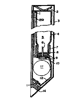
Figures lA and 1B show the Surface Replica fuel cell 12
configured into a plastic case 3 with a rechargeable battery
11 to provide power for a cellular phone. The fuel cell is
held in place through rivets 1 and a fuel needle 6 with
rubber seals 9. Electrical contact is made through
electrical contacts 10 on the fuel electrode and contact
CA 02277133 1999-07-OS
WO 98/31062 PGT/US98/01693
9
rivets 1 on the oxygen electrode. In the fuel cell package
the fuel cell 12 is wrapped around the rechargeable battery
11. The fuel 5 is contained in a fuel tank bottle 4. The
fuel 5 is delivered to the fuel cell 12 through the fuel
needle 6. The refueling operation is to open the case 3 and
snap in the fuel bottle 4 after puncturing the rubber
membrane 8 held by the bottle cap 7. The fuel bottle 4 is
held in place by the holding spring 2. The holding spring
also has a snap-in bump 159 to latch on the cellular phone.
The holding spring 2 and positive electrode 14 in this
embodiment are one piece of cut and formed sheet metal.
Negative electrode 13 is also of one-piece construction. For
this particular embodiment the positive and negative
electrodes 14 and 13 are configured to mate with the Motorola
MicroTAC~ cellular phone and recharging yoke. The power
supply may be electrically recharged as well as fueled.
Figure 2 shows an enlarged cross-sectional view of the
fuel needle connections. In this drawing the fuel bottle 4
filled with fuel 5 is shown impaled on the fuel needle 6. In
operation, the fuel 5 is drawn into the fuel needle 6 through
the capillary tube 15 in the needle. The capillary tube 15
is filled or sized to act as a fuel wick to move fuel to the
fuel cell in a controlled manner. Once fuel reaches the base
of the fuel needle 6 there are fuel flow ports 27 in the side
of the needle to allow the fuel to wick or evaporate out into
the fuel manifold 22 and to be delivered to the fuel
electrodes 21. The transport through the fuel manifold 22
may be by evaporation and condensation or by liquid wicking
through the center of the fuel manifold 22. The two fuel
cell 12 electrolytes 20 are shown. It is a system of two
fuel cells 12 stacked back to back. To assure sealing of the
fuel bottle 4 to the fuel cell 12 there are three gaskets:
The first is the rubber membrane 8 that seals the bottle cap
7 to the fuel bottle 4 and to the fuel needle 6. The second
is the upper ring gasket 24 which is held down with the rivet
fold out 16. The gasket seals to the fuel needle 6 and the
CA 02277133 1999-07-OS
WO 98/31062 PCT/US98101693
fuel cell 12 and also acts as a gentle mechanical clamp of
the paper like fuel cell 12. The third gasket is the lower
gasket 25 that forms the other side of the gentle mechanical
clamp. and seal to the fuel cell 12 and the fuel electrode
contact 26. The electrical contact is made to the fuel cell
by the fuel contact electrode 26 and the contact washer 28.
The air manifolds 18 along with the air electrodes 19 are
cleared off around the impaling point of electrical contact.
The negative sheet metal contact electrode 13 is shown taking
the current out of the picture.
Figures 3A and 3B show exterior views of how the fuel
cell 12 looks when laid out flat. The positive air
electrical rivet connections 14 are shown clamping the ends
of the fuel cell 12 outside the fuel cell region 30 and the
rim seal 32. The philosophy is to keep the air electrode
contact region 29 away from the electrolyte 20. The fuel
rivet 31 makes it's fuel and electrical connection in the
center of the fuel cell 12. The current from the fuel cell
is delivered to the external robust electrical contacts
through the sheet metal contacts 13, 14. One of the
engineering challenges in these contacts is to make
connections from a bulk metal system to the thin mechanical
and electrical fuel cell structure without tearing or
fatiguing the structure of the fuel cell 12. The rim seal 32
is a heat welded or glued seal. In the Figure 3A view the
air manifold 30 is covering the fuel cell. A microscopic
cross-sectional view of the manifold in Figure 3B
schematically shows an expanded Teflon structure 34 with
Nafion~ 35 wetting the outer surface of the Teflon fibers 34.
On the outer surface of the Nafion~ 35 coating is a water
vapor impermeable but oxygen permeable film 157. The coating
157 has cracks and holes 158 that open up when the Nafion~ 35
expands upon high moisture content and close down with low
moisture content. That provides a mechanism of regulating
the moisture content around the fuel cell. That structure
also keeps condensed water from building up on the surface of
CA 02277133 1999-07-OS
WO 98/31062 PGT/US98101693
11
the electrode while allowing water to condense on the outer
surface of the air manifold. The condensed water is wicked
across the outer surface of the air manifold or evaporated
away to the outside air 36. The outer region 35 provides a
moisture regulating source for the fuel cell.
In Figure 4A the contact rivets 14, 31 and air manifold
30 have been removed and only the air electrode pattern is
displayed. The air electrode pattern 38 is deposited through
masks on top of a porous plastic substrate 43. As shown in
Figure 4B the first layer put down is the electrolyte 20 as a
solution deposit of 5% Nafion~ in alcohol solvents (Solution
Technology Inc., P.O. Box 171, Mendenhall, Pennsylvania
19357). It is then dried, ion milled to roughen the surface,
and coated in a vacuum chamber with a sputter deposit of
catalyst film 46, such as platinum. A bulk conductor film
47, such as gold, is sputter deposited. A hydrophobic film
44 such as plasma polymerized Teflon is deposited onto the
outer surface of the electrode. With the present system the
electrolyte 20 is kept free of condensed water by the
hydrophobic layer 44, and air 49 electrolyte interfaces 48
are maintained within the fuel cell electrode pores 45. The
air 49 diffusion path is kept short by using sub micron pore
diameters 45. The fuel electrical connections 10 shown in
Figure 1B are provided for by keeping the oxygen electrodes
47,46,44 masked away from the fuel connection 40. The
positive electrical connections 14 are provided for by
masking off the electrolyte 20, and the hydrophobic film 44,
leaving a gold contact areas 37. The electrolyte 20 may also
be removed by ion milling. The separations 42 between the
fuel cells may be masked out during the deposition of the
- catalyst film 46 and bulk conductor film 47. In the
separation regions 42 between the fuel cells the electrolyte
is ion milled away, and the hydrophobic film 44 deposited.
The fuel cell system has two sets of fuel cells 39 and 41
going away from the fuel connection zone 40.
In Figure 5A the underlying electrolyte matrix layer is
CA 02277133 1999-07-OS
WO 98/31062 PCTIUS98/01693
12
shown. The starting material is a porous membrane such as
etched nuclear particle track plastic membrane Nuclepore~ 59
as shown in Figures 5B and 5C. Through contact regions 51,
52, 57 are obtained by sputter depositing the bulk conductor
though the porous membrane 59. Before the electrolyte 20 is
deposited, the through deposits are created by using a
succession of bulk conductor deposits followed by an ion mill
to work the deposit through the pores 58 in the membrane.
That is done to both sides of the membrane to complete the
through contact regions 51, 52, 57. The electrolyte 58 is
deposited as a solution of 5% Nafion~ in alcohol solvents by
dip and dry. The fuel cell gaps 50 are cleared of
electrolyte 20, 58 by ion milling. The surface of the
through contacts 51, 52 may also be cleared of electrolyte
20, 58 by ion milling. The fuel cell regions 53, 54 are left
covered with electrolyte for the fuel cell electrodes 38
shown in Figure 4A.
In Figures 6A and 6B the fuel electrode deposits are
shown. The fuel cell electrode regions 60 are masked off
with cell separation gaps 42. The electrical contact 55 is a
bulk metal through contact. The microscopic details of the
electrodes are shown in cross-section. To form the fuel
electrode the same sequence of deposits, that are going on
for the opposite side of the porous plastic membrane
substrate 59, is used. The Nafion~ electrolyte 58 is
deposited, onto the porous substrate 59. The fuel electrode
pattern 60 is deposited through masks on top of a porous
plastic substrate 59. The first layer that is put down is
the electrolyte 20, 58 as a solution deposit of 5% Nafion~ in
alcohol solvents (Solution Technology Inc. PO Box 171,
Mendenhall, Pennsylvania 19357). That layer is then dried,
ion milled to roughen the surface and coated in a vacuum
chamber with a sputter deposit of catalyst film 63 such as
platinum. A bulk conductor film 62 such as gold is sputter
deposited. A hydrophobic film 61 such as plasma polymerized
Teflon is deposited onto the outer surface of the electrode.
CA 02277133 1999-07-OS
WO 98/31062 PGT/US98/01693
13
With the present system the electrolyte 58 is kept free of
condensed water by the hydrophobic layer 61, and fuel gas 150
electrolyte interfaces 64 are maintained within the fuel cell
electrode pores 45. The fuel electrode deposits are coated
over the electrolyte matrix previously shown in Figure 5 to
make the through connections 51.
In Figures 7A and 7B the fuel manifold is shown. That
is the central layer of the fuel cell 12 and the manifold 22
presses up against the two sets of fuel cells 12. The second
set of fuel cells is a duplicate set. In the microscopic
cross-section the manifold material is a hydrophobic material
such as expanded Teflon fibers 34. The central region 65 of
the manifold is made hydrophilic with a coating such as
Nafion~. The outer surfaces 66 of the manifold are
hydrophobic. A hole 67 is provided for the fuel inlet.
Figure 8 shows an exploded view of the fuel cell
assembly. The air electrode contact rivets 1 are shown with
the rivet fold outs 16 clamping the air electrodes 19
together and making electrical contact. The fuel needle 6
pierces through the center of the fuel electrodes 21 and the
fuel manifold 22 to make electrical contact through the
contact washer 28. The clamping pressure and sealing is done
through the lower gasket ring 24, and upper gasket ring 25.
The through contacts 51 are shown at the trailing edges of
the air electrode pattern 19 and then over to the edge of the
leading edges of the fuel electrodes 21. That pattern of
connections achieves the desired series cell connections
current path "sewn" through the single membrane 59. The air
manifolds 23 are show sandwiching the first set of fuel cells
68, the fuel manifold 22 and the second set of fuel cells 69.
The stack of membranes is heat or glue sealed at the rims 32
sealed on the edges of the air manifolds 23. The fuel cell
assembly 12 is placed in the power supply system shown in
Figure 1.
Figure 9 shows an enlarged view of a hybrid design of
the Surface Replica Fuel cell electrodes with powder
CA 02277133 1999-07-OS
WO 98/31062 PCT/US98/01693
14
catalysts and a semi-permeable electrode. The first notable
feature of the present design is the semi-permeable electrode
that is made of three layers. The first film is a hydrogen
permeable metal film 79 that is deposited with a wide angle
sputter source to form plugs 80 in the pores 82 of the porous
material 81 or directly coating on the solid electrolyte 83.
An example is a 20-nanometers thick palladium film on a
Nuclepore~ filter membrane with 15-nanometer diameter pores.
A second structural metal film 78, such as platinum, is
deposited onto the hydrogen permeable metal film 79 to
mitigate the hydration induced cracks that occur in many of
the highly permeable metals such as palladium. A third
hydrogen permeable metal film 77, such as palladium, is
deposited over the structural metal film 78. The third layer
of metal, such as a blend of Pt/Ru/Pd, needs to be capable of
accepting hydrogen ions and be catalytically active to the
alcohol fuels.
The dynamics of the layered structure is that the two
outer metal films 77 and 79 have a high hydrogen
permeability, high concentration of hydrogen ions, and have a
high rate of surface acceptance of hydrogen ions. They serve
as reservoirs of mobile ionized hydrogen on either side of
the structural metal film 78. The structural metal film 78
by itself has a low surface rate of acceptance of hydrogen
ions, and has a low equilibrium concentration of hydrogen
ions, but, with the surface coatings 77 and 79 acts as an
efficient conduit of the hydrogen ions and it does not
fracture due to hydration. An alternate method of forming
the semi-permeable electrode is with the deposition of a
metal alloy that exhibits a high permeability to hydrogen
ions, low permeability to other ions, does not fracture due
to hydrogen hydration, and its surface is catalytically
active for hydrogen and alcohol.
On the surface of the hydrogen ion only permeable
electrode 77, 78, 79 powder catalyst particles 76, such as
Pt/Ru coated activated carbon (Pt 20~ wt, Ru, 10% wt. on
CA 02277133 1999-07-OS
WO 98/31062 PGTIUS98/01693
WLCAN X-72R Carbon, from Electrochem Inc., 400 W. Cummings
Park, Woburn, MA 01801), are deposited as a slurry ink with a
solution of 5% electrolyte Nafion~ dissolved in alcohols
(Solution Technology Inc. PO Box 171, Mendenhall,
Pennsylvania 19357). The deposited slurry 76 is dried, ion
milled, and sputter coated with a 30 nm Pt/Ru film 74 to
enhance the electrical connections 75 of the catalytic
particles 76 to the outer permeable membrane 77. The 30-nm
Pt/Ru film 75 has pores 73, for the alcohol fuel 71
permeation, due to shadowing of particles 76 and the
expansion of the electrolyte 72 when it is hydrated.
The alcohol fuel 71 shown as a 1:1 mixture of methanol
and water 96 diffuses into the fuel electrolyte 72 and then
catalytically cracks on the catalyst surfaces 76 and 77, with
a net production of hydrogen ions 151. The hydrogen ions 151
move from the catalytic particles 76 into the outer permeable
membrane 77 by either diffusing through the particles 76 or
going into the fuel electrolyte 72 and into the permeable
membrane 77. The hydrogen ions formed on the outer permeable
membrane 77 from the cracking of the methanol and water 96
diffuses into the permeable membrane 77. The electrons 152
removed in the process of forming the hydrogen ions from the
fuel 96 move through the electrode 76, 77, 78 to the external
electrical load and arrive at the oxygen electrode 86,87,88,
89.
To deliver fuel to the fuel electrode 75,76,78, and 79 a
porous hydrophobic fuel manifold 70 is used to allow only
fuel vapor to reach the electrode surface 74. The fuel
manifold 70 is made of such materials as expanded Teflon or
Microporous~ polypropylene (3M corporation).
The hydrogen ions 151, after they are absorbed into the
outer permeable metal 77, diffuse through the structural
metal 78 and on to the electrolyte interface of the plugged
pore 80 and the electrolyte 83. The electrolyte may be a
solution deposited Nafion~ and it may be chemically different
from the fuel electrolyte 72 because it is separated by the
CA 02277133 1999-07-OS
WO 98/31062 PCT/US98/01693
16
hydrogen ion only permeable electrode 77,78, 79. At the
interface of the plugged pore 80 and the electrolyte 83 is
where the hydrogen ions enter the electrolyte 83. The
hydrogen ions then travel through the electrolyte filled
pores 82, 84 of layers of porous substrate plastic, such as
Nuclepore~ filters. The pores 84 in the inner porous
membrane 84 are chosen to optimize the porosity, to optimize
the conductivity, diffusion rates, and system costs. When
the hydrogen ions 151 reach the oxygen electrode 86, 87, 88,
89, 154, 155 they combine with oxygen ions 153 near the
catalytic surfaces of the oxygen electrode 86, 88, 89, 154.
The oxygen ions 153 are created by the catalytic action
of the catalysts 86,88, 89, 155 on the dissolved oxygen gas
91 in the electrolyte 83. The end product of the combining
of the hydrogen ions 151 and the oxygen ions 153 is water 94.
The product water 94 is dissolved in the electrolyte 83 and
then diffuses out as product water vapor 94. A porous
hydrophobic coating is deposited over the surface of the
catalytic particles 89 and electrolyte 83 to prevent liquid
water from condensing on the outer surface of the oxygen
electrodes 89, 83.
The oxygen electrodes 153, 154 are formed by sputter
depositing a film of metallic conductor 154, such as gold,
onto the porous substrate 81, and then sputter depositing a
catalytic film 155, such as platinum, over the metallic
conductor 154. The electrode 154, 155 and porous substrate
81 is solution coated with an electrolyte such as Nafion~
83.
The oxygen electrodes 86, 87,88 are formed by sputter
depositing a film of catalyst 86, such as Pt, onto the
Nafion~ coated porous substrate plastic 81. A second bulk
conductor metal film 87, such as gold, is then sputter
deposited. An outer catalytic surface film 88 is sputter
deposited over the bulk conductor film 87. The sandwich of
the fuel electrode membrane 81, 77, 78, 79 with the inner
porous film 84, and the oxygen electrode 81, 83, 86,87,88 is
CA 02277133 1999-07-OS
WO 98/31062 PG"T/US98ro1693
17
assembled with a 5% Nafion~ solution and dried. Powder
catalyst particles 89 are added as an ink slurry of 5% Nafion
~ solution. The hydrophobic coating 90 is deposited by
vacuum plasma polymerization of PTFE monomer. That film is
added to prevent liquid product water from condensing on the
surface of air electrodes 89. An ion milling step may be
added to increase the electrolyte 83 surface-to-air contact
91.
By surface pit 93 shadowing and grazing angle deposition
of PTFE, or,by simply depositing a porous film deposition,
the outer electrode surface 89, 93 is made permeable to air.
Pressed up against the fuel cell electrode 90 is a
hydrophobic porous gas manifold membrane 92, such as expanded
PTFE. Two films that regulate the water content of the fuel
cell are built onto the fuel cell. The first is a film 90
that is preferentially permeable to oxygen and less permeable
to water located on the surface of the oxygen electrode 89,
83. The film is formed by plasma polymerization of
polychlorofluroethylene film 157 over the surface of a porous
substrate 161, such as Nuclepore~ filter. The output of the
fuel cell is delivered through electrons 152 through the
electrical load 160.
Figure 10 shows the deposition patterns on the porous
plastic substrate to form a folding assembly fuel cell. In
this embodiment the fuel electrodes 107 and the air
electrodes 103 are formed by coating a single sheet of porous
plastic membrane 97 such as Nuclepore~ filter membranes with
layers of materials as described in Figure 9.
There are four general deposits to form the fuel cell.
The first is a bulk electrode metal deposit, such as gold,
deposited in all the fuel electrode areas 107, the wrap
around electrodes 106, the air electrode areas 103, the
positive frill contacts 104 and the negative frill contacts
101 through masks. The frill contact areas 104, 101 are
slitted 98 to form finger-like contacts with bulk metal end
caps. These bulk electrical conduction electrodes may be
CA 02277133 1999-07-OS
WO 98/31062 PCTlUS98/01693
18
tapered in thickness to optimize the conductivity and cost;
thinnest at the edges of the fuel cell membrane 97 parallel
to the electrode fold 105, and thickest in the wrap around
electrodes 106. The fuel tab 100 may also be coated with the
bulk metal conductor to improve the impermeability to fuel.
The fuel tab 100, cell breaks 102, and frill contacts may be
impermeable areas of the membrane created by heat annealing
after irradiation and before etching the Nuclepore material
substrate 97.
The second coatings of the fuel cell electrodes 107 are
sputtered, evaporated or sprayed onto the electrode regions
through masks, as described earlier.
The third set of electrodes, the air electrodes 103, are
sputtered, evaporated or sprayed onto the electrode regions
through masks. The fourth layer is the electrolytes such as
solution deposited Nafion~ and in general is impregnated
throughout the internal porous areas of the etched nuclear
particle tracked membrane 97. The electrolyte is deposited
over the fuel cell electrodes 107, and 103. Figure 9 shows
the details of the electrolyte deposits. The electrolyte is
either not deposited or removed as by ion milling from the
frill contacts 103, 101, fuel tab 100 and the cell electrical
separations 102. When the cell is folded on the center line
105 the rim seal area of the fuel cell 99 is shown going
around the rim of the fuel tab 100 and the fuel electrodes
107.
Figure 11 shows the insertion of the inner membrane and
folding assembly. The inner porous membrane 109, such as a
Nafion~ impregnated Nuclepore~ filter, is inserted between
the folded 105 fuel electrodes 107 and the air electrodes
103. Electrolyte solution 108, such as 5~ Nafion~
solution, is added between the fuel electrodes 107 and the
air electrodes 103. The assembly with the Nafion~ is dried
and cured between 80 and 110 degrees centigrade. The wrap
around electrodes 106 are shown going around the electrode
fold 105. The frill contacts 110, 104, 101 are shown as
CA 02277133 1999-07-OS
WO 98/31062 PCT/US98/01693
19
slits 98 in the membrane. The rim seal is shown going around
the fuel electrodes 107 and the cell breaks 102. The fuel
inlet tab 100 is shown.
Figure 12 shows an exploded view of the fold-over fuel
cell 112 assembled with the air manifold 113 and the fuel
manifold 111. The air manifold 113 is a hydrophobic air
permeable sheet material such as expanded PTFE, that is
pressed up to the fuel membrane 112. The fuel manifold has
an inner porous hydrophobic surface, such as expanded PTFE,
and an inner zone 65 that wicks fuel, as shown in Figure 7.
The outer surface of the fuel manifold is a membrane that is
impermeable to fuel and water but permeable to carbon dioxide
such as polychlorofluoroethylene (Kel-F~ 3M corporation).
The fuel manifold outer surface carbon dioxide permeability
provides an exit for the product carbon dioxide produced by
the cracking of methanol and other hydrocarbons. To provide
a high enough carbon dioxide permeability and cost
effectiveness the outer surface of the fuel manifold may be a
lamination of a Nuclepore~ membrane vacuum deposited
polychlorofluoroethylene and a protective gas permeable
lacquer coating such as cellulose nitrate. The fuel manifold
111 is pressed against the fuel cell membrane 112 and the
system is heat sealed or glued with a polyester epoxy along
the rim seal surfaces 114.
Figure 13 shows the assembly of the folded fuel cell
into a cylindrical geometry to match the physical profile of
a standard D-cell battery. The fuel cell assembly 117 is
wrapped around with the air manifold surface 113 facing out.
The fuel tab 100 is bent over to be punctured by the fuel
needle and terminal cap 115. A fuel gasket 116 is placed
above the fuel tab 100 and a fuel gasket 118 is placed below
the fuel tab 100. The negative frill tabs 101 bends and
makes a cantilever beam spring contact against the inner
surface of the negative terminal cap 115. The positive frill
tabs 104 bends and makes a cantilever beam spring contact
against the inner surface of the negative terminal cap 122.
CA 02277133 1999-07-OS
WO 98/31062 PCT/US98/01693
The fuel filled fuel tank 119, such as a methanol and water
filled and sealed polyethylene cylinder, slides up inside the
fuel cell assembly 117. The fuel connection to the fuel cell
is made when the fuel tank 119 wall is punctured by the fuel
needle terminal cap 115. The terminal caps 115, 122 are held
together by attaching to the dielectric tube 121, such as by
threading and screwing the caps and tube, gluing or heat
fusing the dielectric tube to the end cap. A gap 130 in the
fuel cell assembly 117 is left, and the dielectric tube 121
is made transparent to allow the fuel level to be visually
checked. The dielectric tube 121 has vent holes 120 formed
in it to allow air in and product gases and vapors out. The
number of vent holes and sizes are strategically used to
throttle the oxygen diffusion intake and water diffusion
removal rate.
Figures 14A, 14B and 14C show the assembled fuel cell in
a standard D-cell physical profile. Three views are shown:
the exterior side view in Figure 14A, a side cross section
through the centerline in Figure 14B, and the vertical view
horizontal cross-section in Figure 14C. The exterior view
drawing shows the major dimensions of the standard D-cell
battery 162 which is 5.8 cm long and 3.3 cm in diameter.
In the vertical cross section, the positive terminal cap 122
is electrically contacted to the fuel cell 126 through the
frill contacts 104. The fuel tank wall 124 is designed to
have an end alignment bump 123 to provide a centering and
positive pressure point on the fuel tank 124. The alignment
bump 123 may also be the heat seal-off point after filling
the fuel tank. At the other end of the fuel tank 124
skewering on the fuel needle 127 provides the centering
alignment. The negative terminal cap 115 is electrically
connected to the fuel cell 126 through the negative frill
contacts 101. The fuel needle 127 is shown penetrating the
fuel tank wall 124, immersed in fuel 125, and sealed by the
fuel gaskets 118 and 116. The fuel path mechanism through
the needle and to the fuel cell tab 100 is the same as in
CA 02277133 1999-07-OS
WO 98/31062 PCT/US98/01693
21
Figure 2 except that the contact washer 28 and rivet fold-out
16 are not used, since the negative electrical connection in
that case is made through the frill contacts 104 instead of
the fuel connection. In the horizontal cross sectional
view the fuel window gap 130 is shown to allow the fuel level
to be conveniently visually checked. The fuel tank wall 124
and the dielectric tube 121 need to be transparent in the
window gap 130 area for the fuel checking scheme to work. An
air flow gap 128 is left between the fuel tank and the inner
surface of the fuel cell 126 to allow carbon dioxide to be
removed by diffusion. An air flow gap 129 is left between
the dielectric tube 121 and the fuel cell outer surface 126
to allow oxygen in diffusion and water removal from the fuel
cell 126 out through the vent holes 120.
Figure 15 shows a schematic view of how the fuel cells
are coupled to a water and heat counter flow heat exchanger.
In the event that the fuel cells' power levels are high
enough to merit active air flow or need the advantage of
operating the fuel cells above ambient conditions, such as 80
degrees centigrade. A scheme of using a counter flowing heat
exchanger with a heat transfer membrane 139 is shown. The
heat transfer membrane 139 conducts heat and moisture between
the in flow 131 and out flowing air 144. The water permeable
membrane 139 may be a composite structure such as Nafion~
impregnated Nuclepore~ filter that is moisture permeable due
to the Nafion~ and obtains it's structural strength from the
porous Nuclepore~ substrate. In operation the inlet air 131
is fanned 156 into the entrance line 140. As the air is
heated by the outgoing air 144 it absorbs moisture diffusing
through 143 the heat exchange membrane 139. Heat and
moisture are exchanged between the in flowing air 140 and the
out-flowing air 142 with the counter parallel gas flow 141.
The inlet air 131 arrives at the air electrode 138 heated
and humidified. The fuel cell 136, air electrode 138,
electrolyte 137, fuel electrode 134, fuel I35, and the heat
exchange system are thermally insulated 132.
CA 02277133 1999-07-OS
WO 98/31062 PCT/US98/01693
22
The above descriptions contain specific examples that
should not be construed as limitations on the scope of the
invention, but rather as exemplifications of preferred
embodiments. Nafion~ electrolytes and Nuclepore~ filter
materials were chosen because they have well-known
properties. Many other variations are possible.
Microstructure
Many of the new concepts that are to be added to the
previous patent application are to solve the problems of
using hydrocarbon fuels, or simply using dirty fuels with
impurities that may diffuse through the fuel cell. If these
hydrocarbons such as methanol or ethanol diffuse to the
oxygen electrode it reduces the performance of the oxygen
electrode as well as being simply a leak of fuel un-used by
the fuel cell. Conventional fuel cell techniques to prevent
these losses are to use thicker electrolytes, run the fuel
cells at sufficiently high power densities to attempt to use
all the fuel before it reaches the oxygen electrode, and
lower the concentrations of the fuel. All three of these
techniques have the problem that they simply increase the
resistance to alcohol or impurity diffusion rate at the
expense of some other performance parameter. The unique
solution is to electrochemically catalyze the hydrocarbons
on an electrode and then have the hydrogen ions move through
an electrode which is permeable to.hydrogen but not to the
hydrocarbons. The hydrogen ions then re-emerge out of the
electrode into the second electrolyte and travel to the
oxygen electrode. That scheme is formed with two outer
electrodes and a third inner separate diffusion electrode or
the diffusion electrode may be the under-layer of either the
fuel or oxidizer electrodes. The particular case of interest
for the hydrocarbon electrode is a Pt/Ru alloy dispersed over
a Pd/Ta/Pd or Pd/Pt/Pd hydrogen permeable electrode. The
inner support metal identified as Ta or Pt may be a variety
of hydrogen permeable materials such as the transition metals
which are permeable to disassociated hydrogen. Such as Pd/Ag
CA 02277133 1999-07-OS
WO 98/31062 PCT/LTS98ro1693
23
77%:23% atomic percent alloy (suitable for hydroxide
electrolytes). The selection of the material also depends on
the compatibility with the electrolyte. The Pt/Ru side of
the electrode is immersed in an alcohol and sulfuric acid
electrolyte. The oxygen electrode is a Pt/Ru electrode or
other suitable oxygen electrocatalytic metal. The oxygen
electrode uses a solid polymer electrolyte.
Electrolyte Optimization
Three features come out of the small pore geometry of
the porous substrate and the electrolyte. The first is the
simple optimization of the electrolytes' conduction to
diffusion rates for the performance range expected by the
fuel cell. To optimize the fuel cell the desired current
density is estimated and then the ohmic loss versus reactant
diffusion rates is optimized. An example of optimization is
a fuel cell in which the reactants are delivered to the
electrodes by diffusion. The heat removed by ambient air
cooling with an internal air gap of 2.9 mm, and a target of,
keeping the fuel cell temperatures from rising above 80
degrees centigrade, sets the current density limit bellow
approximately 5o milliamperes per square centimeter. The
current density is approximately 1/50th of state-of-the-art
solid polymer fuel cells (US 5,234,777). Thus, the
electrolyte filled pores of the support membranes are used to
choke off the diffusion and ionic conduction flow to keep the
fuel cell at the optimum ionic conductivity and reactant
diffusion resistance values. With that mechanism of
containing the electrolyte and reducing the porosity, as the
structure is thinned to maintain optimum performance, it
leads to the total utilization of the electrolyte scaling
inversely proportional to the square of the thickness of the
porous substrate. That reduces the use of expensive
electrolytes, such as Nafion~, and subsequently the cost of
the fuel cells.
The second feature comes from the suspected molecular
alignment of the solid polymer electrolyte, such as Nafion~
CA 02277133 1999-07-OS
WO 98/31062 PCT/US98101693
24
by being organized by the collimated high surface area of the
etched nuclear particle track membranes or dielectric with
similar structures. Enhancements of the conductivity of up
to 20 times the homogenous electrolyte is expected. If the
diffusion permeability for the molecular species is constant
then that also results in a net 20 times ion over diffusion
rate enhancement.
A third effect is if the mean free path between
molecular diffusion species (such as hydrogen gas) is similar
to or larger than the dimensions of side channels in a porous
structure there is a decrease in the diffusion rate over the
simple-gradient cross-sectional-area model. The diffusion
characteristics fall into the regime of molecular flow
diffusion in vacuum systems where wall convolutions, such as
in bellows pipes, may effect the conductance of the pipe. The
effect is also embodied as providing collimated conduction
paths for the ions and lateral dead end pockets for molecular
species. The specific embodiment is the stacking of two or
more membranes with pores smaller than the molecular species
mean free path, wherein the inter-membrane gaps act as the
side channels. Or simply having side channels to the main
ion paths in the system on the scale of the molecular
specie's mean free path between their molecules. The present
diffusion resistance mechanism may also be used in other
mixed ion and non-ion diffusion systems such as photovoltaic,
thermoelectric and thermionic systems as well.
Fold-Over Design
A very simple scheme of forming all the electrodes of
the fuel cell on a flexible single substrate sheet is a fold-
over design. In that design the cell interconnection routes,
cell electrical separations, and fuel and oxidizer electrodes
are made on one side of a membrane. The fuel cell is then
assembled by folding the' membrane. That design also permits
the fuel cells to be formed from commercially available
uniformly porous substrates such as Nuclepore~ filters, where
any number of inner electrolyte layers may be inserted. The
CA 02277133 1999-07-OS
WO 98/31062 PCT/US98/01693
extra degree of freedom in the fuel cell construction helps
optimize the fuel cell by constricting the porosity.
Controlling the micro geometry of the electrolyte is
beneficial to the performance of the fuel cell. The inner
membrane is used to preferentially block different molecular
species over the ion transport by geometrical design or
chemical properties.
Layers of Electrodes
There are two principal functions of the fuel cell
electrodes: the first is to electrocatalyze the fuel or
oxidizer, and the second is to electrically conduct the
electrons out of the fuel cell to the electrical load. These
two functions and properties are not often embodied in a
single complementary material: A high surface area catalyst
structure that has a low electrical conductivity because of
the tortuous electrical path through the structure, and a
high electrical conductivity structure that has a smooth
surface with minimal surface area. A way to have the best of
both materials is to have a smooth electrode layer coupled
with a high surface area catalyst, such as sputter deposited
gold film electrodes covered with catalysts supported by
activated charcoal powder.
Simple Masking
A simple method of forming an array of fuel cell
electrodes on porous dielectric substrates is to sputter,
vacuum evaporate or spray metals and electrolyte solutions
through mask patterns. Directed deposits like ink jet
printing or molecular beam deposit may be used. Directed
removal methods such as ion milling and laser ablation are
used to define the electrodes. The previous patent
application US 08/531,378 described more sophisticated
methods of creating self masking substrates. For the
uniformly porous plastic substrates that are commercially
available, such as Nuclepore~ filters, forming the electrode
patterns through masks is simple and practical. Many other
printing and lithographic techniques may also be used to
CA 02277133 1999-07-OS
WO 98/31062 PCT/US98/01693
26
place the fuel cells and circuits onto the porous plastic
substrate. Ink jet printing may be used to spray on the
electrode patterns and fuel cell electrodes that are
formulated as slurries of catalytic, and conductive particles
and or electrolytes. The use of xerography is also possible
where the patterned materials; catalytic, conductive,
electrolyte, or insulator particles are electrostatically
attracted to the surface of the fuel cell substrate.
Combinations of using the vacuum vapor deposited electrode
patterns to then be thickened by electroplating or attracting
charged particles are used to build on the patterns from a
previous deposition. Photolithography and/or electrochemical
processes are also used to define or form electrode patterns.
Collimated Electro rtes
A unique feature of using an electrolyte that is locked
into a collimated dielectric material is that it has no
lateral conductivity. Diffusion of reactants are limited
primarily to the direction of the collimated pores. These
two properties pose an advantage to a fuel cell system of
adjacent fuel cell stacks on a single membrane. If the
electrolyte is eliminated from the surface substrate in the
electrical separation areas, between adjacent fuel cells, the
shunting route is cutoff. Another variation is that the cell
separation areas may simply be non-porous areas of the
substrate plastic before the electrodes and electrolytes are
added. A simple method of doing that with the etched nuclear
particle tracked membranes is to either not irradiate those
regions or thermally anneal them after irradiation and before
etching. Another feature of the collimation is that when
there are pinhole defect leaks in the pore-free electrode the
lateral spreading of the fuel leak is confined to the fuel
cell electrode directly through the electrolyte due to the
collimation. That limits the degree of oxidizer electrode
poisoning.
Heat and Water Exchanae
A particular problem of water bearing electrolyte fuel
CA 02277133 1999-07-OS
WO 98/31062 PCT/US98/01693
27
cells is that if they are operated at a range of temperatures
or reactant humidities the electrolyte's water content
varies. That may lead to sub-optimum performance of the
electrolyte with the electrolyte either drying out or
flooding the electrodes. To solve that problem a heat and
water counter flow exchanger is used. The design of the heat
and water counter flow exchangers is to use thin water
permeable membranes as the heat exchange elements. For high
rates of heat and water transfer these membranes need to be
thin. The membranes are made of a composite material that
uses a high strength matrix for structural integrity. The
matrix is impregnated with a moisture exchange material such
as Nafion~ or cellulose nitrate.
For a non-actively flowed fuel cell system a moisture
retaining film is used to operate at temperatures above the
point or where the electrolyte dehydrates if directly exposed
to the air. The membrane is formed by coating the oxygen
electrode with a film or the air manifold such that is
permeable to oxygen and less permeable to water. The
membrane is pore-free or has periodic pores. Periodic pores
provide a mechanism of loosing excess liquid water.
Tapered Electrodes
The amount of metal in the electrical conduction
electrodes are optimized in these thin film fuel cell
inventions if the electrode thickness were tapered from the
minimum thickness, for conduction, up to the point where the
electrode leaves the fuel cell and is making the connection
to the next adjacent cell.
Vapor Fuel Deliverv
There are two principal means of delivering methanol
fuel in a small fuel cell that has no moving parts. The
first is to use wicking of the fuel to the fuel cell
electrode. But liquid wicking requires there be liquid
contact with the fuel and the fuel cell electrode. That
leads to problems that were mentioned earlier. If the fuel
is vaporized before it reaches the fuel cell electrodes the
CA 02277133 1999-07-OS
WO 98/31062 PCT/US98/01693
28
problems of physical contact are eliminated. What is used is
a combination of liquid fuel being wicked out of the fuel
bottle, wicking the fuel into a layer near the fuel cells and
then using vapor transport through a hydrophobic matrix to
reach the surface of the fuel electrodes. For these low
power density fuel cells where the air electrodes are
ambiently cooled and supplied with oxygen only through
diffusion the fuel vapor diffusion rates are sufficiently
fast enough over 0.1 mm to 20 mm distances.
Pore-Free Electrodes
Very thin flexible metal foils are supported by a
plastic substrate in the present invention. The practical
use of these foil membranes is to fill the need in the
directly fueled alcohol fuel cells to block methanol
diffusion through the electrolyte while efficiently
conducting the ionic current. A metallic foil solves that
problem if the foil is made thin enough to satisfy the
necessary throughput rate and economics. To form the thin
foil electrode a large range of metallic elements, that
exhibit hydrogen chemisorption, are deposited onto the porous
substrates or directly on a solid electrolyte. The plugging
of the pores is done with a wide angle hydrogen permeable
metal sputter deposit that is thicker than the substrate's
pore diameters. In addition the metal foil may be built up
in layers to provide various properties. It is noted in the
literature that below 200 degrees centigrade much of the
diffusion rate of gases through metal foils is dominated by
the chemisorption rate on the surface of the foil (Vielstich,
1965). For pure hydrogen fuel cells, a catalyst surface
layer such as platinum on both sides of the foil increases
the throughput rate of hydrogen through the electrode. With
direct methanol and hydrocarbon fuel cells the hydrocarbon
fuel side of the membrane has to incorporate catalysts that
may catalyze or be immune to hydrocarbon molecules and their
products to avoid poisoning. While on the side of the foil
membrane opposite the hydrocarbon fuel the surface catalysts
CA 02277133 1999-07-OS
WO 98/31062 PCT/US98/01693
29
may be optimized for hydrogen. Other considerations in the
design of the foil are that many of the transition elements
with suitable permeabilities, such as Pd that have very high
hydrogen permeability, have the disadvantage that they expand
as they hydrate and subsequently crack. That property is
fairly common among the metal hydrogen hydrates. Thus, to
prevent the problem of stressing and cracking, the thin foils
are alloyed, such as, by (77:23) palladium alloy that is
currently used in hydrogen purifiers. Another option is to
form the foil membrane in layers. In a layer design the
inner layer has a low equilibrium concentration of hydrogen,
does not crack, and is the structural barrier. While the
outer layers provide the fast surface exchange reaction rates
and surface area. Another feature of layering is that the
first layer deposited has a high permeability rate for
hydrogen ions, while if the second structural layer has low
permeability, the first layer provides a lateral diffusion
route to the substrate pores that effectively lets the whole
structural membrane be used as a diffusion membrane.
As an example, current tests are on Nuclepore~ filters
with 15 nm diameter pores. These membranes have been sputter
coated with first a 3.7 nm Pd film, second a 15 nm Pt film
and third with a 7.5 nm Pd film. At these thicknesses and
geometries the membranes have hydrogen diffusion rates at
room temperatures that are equivalent to 10-20 ma per square
centimeter at 23 degrees centigrade. That is in the
desirable current density range for small ambiently cooled
and diffusion reactant supplied fuel cells. These membranes
are also inexpensive compared to the earlier 12 micron thick
membranes because they use so much less material, at 1/800th
the thickness. The assembly constitutes a methanol fuel cell
that electrocatalytically cracks the methanol with an
electrolyte on the fuel'side of the membrane and then filters
the hydrogen ions, or hydrogen gas and forms a fuel cell on
the other side of the filter membrane in the other
electrolyte. The methanol cracking electrocatalytic process
CA 02277133 1999-07-OS
WO 98/31062 PCTlUS98/01693
requires the addition of water. Thus, it is necessary to
have two electrolytes, one on the fuel side of the pore-free
metal foil and other on the oxygen side. That prevents the
methanol and water cross-over to the oxygen fuel cell
electrode.
Different Electrolytes
A pore-free metal foil barrier in the fuel cell
separating the electrolytes permits the possibility that two
different electrolytes may be placed on either side of the
pore-free metal foil barrier. One arrangement is to make the
methanol fuel electrode the hydrogen only pore-free electrode
using Nafion~ and sulfuric acid on the fuel side and a KOH
electrolyte on the oxygen side of the pore free electrode.
The oxygen kinetics are more favorable in the KOH electrolyte
while acidic electrolytes are used with the fuel side because
the KOH electrolyte forms carbonates if it were used on the
fuel side.
Stoichiometric Fuel Delivery
The pore-free electrode or barrier in the cell also
blocks the ionic drag of water as well as the methanol fuel.
For hydrocarbon fuels where the hydrocarbons are being
reformed to hydrogen and carbon dioxide the source of oxygen
for that process is typically water. In conventional fuel
cells the water either has to be recirculated in the
electrolyte or recaptured from the exhaust products. If the
ionic drag of water through the fuel cell is blocked then
simply adding a stoichiometric mixture of fuel and water is
sufficient to keep the fuel reforming reactions balanced.
For example, with the fuel cell that is electrocatalytically
using methanol fuel it needs to have a stoichiometric fuel
mixture one molecule of water for every molecule of methanol
to allow the methanol to catalytically oxidize and form
carbon dioxide and hydrogen. Thus a 1:1 molar mixture of
methanol and water fuel mixture is adequate to eliminate the
need to recapture water from the fuel cell exhaust. Without
water recapture and circulation the direct methanol fuel cell
CA 02277133 1999-07-OS
WO 98/31062 PGT/US98101693
31
becomes significantly simpler. The oxygen electrode only
needs to retain sufficient product water to avoid being
dehydrated and diminishing it's performance. The fuel
electrode uses water and fuel at equal rates. Thus, when the
fuel cell runs out of water, it also runs out of fuel.
Bulk Electrical Connections
One of the features of these fuel cells is that the
apparent optimum bulk electrical current carrier is gold. A
good figure of merit for a bulk metallic conductor is one
that has a high quotient of conductivity divided by density
and cost per unit mass (cmZ/Ohm*$). In searching for the
most cost effective bulk electrical conductor that may stand
up to the typical corrosive environment of the fuel cells,
gold's cost, high conductivity and inertness gave it a figure
of merit of roughly four times that of platinum. Various
other conductors in the Pt metal group were ranked: Ru 2600,
Pd 1900, Au 1500, Ir 900, and then Pt 390 (cm2/Ohm*$).
Ruthenium has the highest figure of merit of the platinum
group of elements but it's low ductility and possible surface
oxidation makes it less versatile than gold. Palladium in
combination with other materials to avoid cracking due to
hydration is also being studied as an effective bulk metallic
conductor. Palladium is also advantageously used as a
hydrogen permeable electrode and the bulk conductor. Gold's
high conductivity allows the fuel cell coating to be
extremely thin permitting very little loss of active surface
area of the electrodes. Gold films are used as hydrogen
diffusion barriers due to their low permeability to hydrogen.
That property is used to improve the low discharge rate cell
efficiency where fuel diffusion leakage is the major energy
loss mechanism. If the fuel cell electrodes are kept small
in dimension, to keep the mean electrical path from cell to
cell short, the quantity of gold necessary to form the cells
is near the transition point where gold films become good
conductors on surfaces. Transition occurs around a gold
thickness of 5 nm. Other refractory metals in order of
CA 02277133 1999-07-OS
WO 98/31062 PCT/US98101693
32
figure of merit are Mo 654,000, V 463,000, W 328,000, Ti
100,000, Ta 65,000 and C 16,000 (cm2/Ohm*$). The list
continues through the pure elements. Alloys such as Mo2Si3,
and WC have been considered. Many of these refractory
materials have high figures of merit but are difficult to
deposit, may be corrupted in the fuel cell environment,
require much thicker films, or make poor contacts due to
surface oxides.
Fuel Cell/Battery and or Electronics
The electrical system of the power pack is arranged to
have the battery connected electrically parallel to the fuel
cell or through an electrical current and voltage controlling
device. The battery and fuel cell is connected to an
electrical voltage and current source to charge the battery
and reduce the fuel consumption of the fuel cell or to simply
have flexible energy sourcing. A version of the fuel cell
with storage capability for the products uses electrolysis in
the fuel cell to store energy. The external application of
charging voltages also helps clean the fuel cell catalytic
surfaces. The end product is a power device that derives
it's energy from a fuel or electrical charging or both
simultaneously. The charging source may be from a DC
electrical source or pulsed source. Photovoltaic cells are
also used as the electrical source of energy. Another
concept is to mate the fuel cell with a arbitrary wave form
generator and produce any alternating current output desired
by the user. Another hybrid power scheme is to energize a
flywheel with the fuel cell's low continuous output and then
draw off power to match the demand. That works well with
devices such as automobiles that need high power surges for
acceleration and hill climbing, but the average power demand
is only a small fraction of the surge demand.
Applications of the Power Supply
There are a tremendous number of practical applications
for the present fuel cell power pack. The unique designs
shown and described above have been targeted toward providing
CA 02277133 1999-07-OS
WO 98/31062 PGT/US98/01693
33
electrical power for cellular phones and portable radio
transmitters and receivers. Those applications realize a
substantial enhancement over rechargeable batteries by virtue
of higher specific energy per unit mass of hydrocarbon fuels,
such as methanol over nickel cadmium batteries, by factors in
the range of 10 to 100 times. Logically almost all the
portable electrically powered applications that are operated
in human habitable conditions are integrated with the new
fuel cell package. Limits are that the fuel cell costs scale
with the maximum power output, and there needs to be a source
of oxygen or other oxidizer. To preserve the fuel cells,
until they are needed, it is as simple as sealing the fuel
cell in an air tight container to deprive the fuel cells of
oxygen. The new fuel cell invention has been described in
the context of a hydrogen oxygen fuel cell but other
variations of fuels and oxidizer sources, such as a hydrogen
chlorine fuel cell are possible. The pore-free electrode
helps considerably in blocking chlorine gas diffusion.
While the invention has been described with reference to
specific embodiments, modifications and variations of the
invention may be constructed without departing from the scope
of the invention, which is defined in the following claims.