Language selection

Search

Patent 2277196 Summary

Third-party information liability

Some of the information on this Web page has been provided by external sources. The Government of Canada is not responsible for the accuracy, reliability or currency of the information supplied by external sources. Users wishing to rely upon this information should consult directly with the source of the information. Content provided by external sources is not subject to official languages, privacy and accessibility requirements.

Claims and Abstract availability

Any discrepancies in the text and image of the Claims and Abstract are due to differing posting times. Text of the Claims and Abstract are posted:

  • At the time the application is open to public inspection;
  • At the time of issue of the patent (grant).
(12) Patent Application: (11) CA 2277196
(54) English Title: OPERATION PROCESS OF A PUMPING-EJECTION APPARATUS AND RELATED APPARATUS
(54) French Title: PROCEDE DE FONCTIONNEMENT D'UN INSTALLATION DE POMPAGE ET D'EJECTION, ET INSTALLATION S'Y RAPPORTANT
Status: Deemed Abandoned and Beyond the Period of Reinstatement - Pending Response to Notice of Disregarded Communication
Bibliographic Data
(51) International Patent Classification (IPC):
  • F4F 5/54 (2006.01)
  • F4F 5/24 (2006.01)
(72) Inventors :
  • POPOV, SERGUEI A. (Hungary)
(73) Owners :
  • EVGUENI D. PETROUKHINE
  • SERGUEI A. POPOV
(71) Applicants :
  • EVGUENI D. PETROUKHINE (Cyprus)
  • SERGUEI A. POPOV (Hungary)
(74) Agent: SMART & BIGGAR LP
(74) Associate agent:
(45) Issued:
(86) PCT Filing Date: 1998-10-22
(87) Open to Public Inspection: 1999-05-06
Examination requested: 2001-02-19
Availability of licence: N/A
Dedicated to the Public: N/A
(25) Language of filing: English

Patent Cooperation Treaty (PCT): Yes
(86) PCT Filing Number: PCT/IB1998/001689
(87) International Publication Number: IB1998001689
(85) National Entry: 1999-06-23

(30) Application Priority Data:
Application No. Country/Territory Date
97117775 (Russian Federation) 1997-10-29

Abstracts

English Abstract


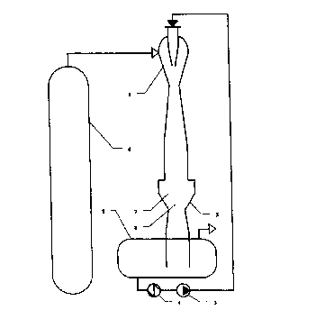
The present invention pertains to the field of jet-generation techniques. A
gas-liquid mixture is fed from a jet apparatus into a jet converter where the
flow of said gas-liquid mixture is first converted by its expansion into a
supersonic liquid-gas flow. This supersonic liquid-gas flow is then slowed
down in a profiled flow section of the converter for generating a pressure
jump and for partially converting the kinetic energy of the flow into pressure
energy. In order to implement this operation process, the apparatus includes a
jet converter for the flow which comprises an expansion chamber as well as a
profiled flow section. The inlet of the expansion chamber is connected to the
outlet of the jet apparatus while the outlet of the profiled flow section is
connected to a separator.


French Abstract

La présente invention se rapporte aux techniques de génération de jets. Un mélange de gaz et de liquide est envoyé d'un appareil à jets dans un convertisseur à jets. Dans ce convertisseur, le flux du mélange de gaz et de liquide est tout d'abord transformé grâce à sa détente en un flux de gaz et de liquide supersonique. Le flux de gaz et de liquide supersonique est ensuite freiné dans une partie d'écoulement profilée du convertisseur de manière à former un saut de pression et à transformer partiellement l'énergie cinétique du flux en énergie de pression. Afin de mettre en oeuvre ce procédé de fonctionnement, l'installation comporte un convertisseur de flux à jets qui comprend une chambre de détente et une partie d'écoulement profilée. L'entrée de la chambre de détente est connectée à la sortie de l'appareil à jets, tandis que la sortie de la partie d'écoulement profilée est connectée à un séparateur.

Claims

Note: Claims are shown in the official language in which they were submitted.


Claims
1. Operation process of a pumping-ejection apparatus, which includes
feed of liquid working medium from separator to pump, feed of liquid working
medium by pump into nozzle of the liquid-gas jet apparatus, formation of the
liquid working medium's flow in the nozzle with its further effusion out of
nozzle, because of this, pumping off gaseous medium and formation of
gas-liquid mixture in the jet apparatus. Gas-liquid mixture from the jet
apparatus is
fed into jet converter, where the flow of gas-liquid mixture, because of its
expansion, is converted into supersonic gas-liquid flow, and then this
supersonic gas-liquid flow is decelerated in the shaped flow part of converter
followed by pressure jump and partial transformation of kinetic energy of the
gas-liquid flow into potential energy of pressure, after what the gas-liquid
flow
from the shaped flow part of converter is fed into separator, where the
gas-liquid flow is separated into compressed gas and liquid working medium.
2. Pumping-ejection system, which contains liquid-gas jet apparatus,
separator and pump, where pump by its discharge side is connected to active
nozzle of the jet apparatus, separator is connected to pump's suction side,
and
the jet apparatus by it's gas inlet is connected to a source of evacuated
gaseous medium, is furnished with jet converter of the flow, which includes
expansion chamber with a shaped flow part. Expansion chamber of the
converter is connected from its inlet part to the outlet of the liquid-gas jet
apparatus, and the shaped flow part of converter from its flow's outlet part
is
connected to the separator.
3. Apparatus as per claim 2, distinguished, as the shaped flow part of
converter is designed as convergent-diffuser.
4. Apparatus as per claim 2, distinguished, as the shaped flow part of
converter is designed as cylindrical one.
5. Apparatus as per claim 2, distinguished, as the shaped flow part of
converter is designed with the ratio of the square of its cross-section in the
zone of its throat to the square of the cross-section of the jet apparatus at
its
outlet from diffuser or the total square at the outlet from diffusers from 1,1
to
200.

Description

Note: Descriptions are shown in the official language in which they were submitted.


CA 02277196 1999-06-23
PCT/IB98/01689
priority of 97117775 ius. appl.
Operation process of a pumping-ejection apparatus
and related apparatus
Description
Technical field
The invention relates to the field of jet technology, primarily to pumping-
ejection apparatus for vacuum creation during vacuum rectification of liquid
products, for example, fuel oil and can be used for rectifying of the oil
stock.
Background Art
The operation process of a jet apparatus is known, which includes the feed
of active medium into the vacuum ejector and pumping off gaseous medium out
of the rectifying column, and jet apparatus for vacuum creation while oil
distillation, which contains vacuum rectifying column, where reduced pressure
is
created with the use of water-steam ejector (see the USA patent) 2028340,
class
196-77, 1936).
In these operation process and related apparatus vapour of the liquid
product mix w~h water vapour, what requires a special cleaning of condensate
of water steam before its discharge into industry drainage, and) as a result,
additional costs for organization of the cleaning process.
The closest analogy to the described operation process and related
apparatus in its technical entity and to the result achieved is the operation
process of a pumping-ejection system, which includes feed of liquid working
medium from a separator to a pump, feed of liquid working medium by the
pump under pressure into a nozzle of a liquid-gas jet apparatus, forming of a
liquid working medium's flow in the nozzle with its further effusion out of
the
nozzle, because of this - pumping off gaseous medium and forming of gas-liquid
mixture in the jet apparatus. The closest analogy of the device for
realization of
this operation process is device, which contains liquid-gas jet apparatus,
separator and pump) the pump is connected by its discharge side to the active
nozzle of the jet apparatus, the separator is connected to the pump's suction
side, and the jet apparatus is cbnnl~led by its gas inlet to the source of
evacuated gaseous medium (see the USSR certificate of authorship, 559098,
MPK 6 F 04 F 5/04, 1977).
With these operation process and r~iated apparatus it becomes possible to

CA 02277196 1999-06-23
PCT/IB98101689
priority of 97117775 rus. appl.
pump off vapour-gas medium, for example, out of a rectifying column by a
liquid-
gas jet apparatus, in which liquid working medium is used as active medium,
what allows to reduce considerably emission of ecologically harmful dirt into
environment.
But in these operation process and related apparatus kinetic energy of a
gas-liquid flow is not fully utilized for transformation of this energy into
potential
energy of pressure, what in tum, leads to high speed of the gas-liquid flow,
when
it enters separator and rather low degree of compression of the gaseous
component of the gas-liquid flow. As a result, the conditions for gas-liquid
flow's
separation into compressed gas and liquid working medium in the separator
deteriorate, and separator's construction should include additional elements
for
reduction of flow's speed and foaming.
Disclosure of Invention
The problem to be solved in this invention is improvement of system's
operation effectiveness by creation of conditions for use of the gas-liquid
flow's
kinetic energy to increase the compression degree of the gaseous component of
the flow and reduce, because of this, the flow's speed at separator's inlet.
This problem is solved by the following: in the operation process of the
pumping-ejector system, which includes feed of liquid working medium from a
separator to a pump) feed of liquid working medium by the pump into nozzle of
a
liquid-gas jet apparatus, formation of a liquid working medium's flow in the
separator with its further effusion out of the nozzle) because of this,
pumping off
gaseous medium and formation of gas-liquid mixture in the jet apparatus) gas-
liquid mixture from the jet apparatus is fed into jet converter, where the
flow of
gas-liquid mixture, because of its expansion, is converted into supersonic gas-
liquid flow, and then this supersonic gas-liquid flow is decelerated in a
shaped
flow part of the converter followed by pressure jump and partial
transformation of
kinetic energy of gas-liquid flow into potential energy of pressure. The gas-
liquid
flow from the shaped flow part of converter is fed into separator, where gas-
liquid flow is separated into compressed gas and liquid working medium.
As for related apparatus for embodiment of the above-mentioned
operation process, the: mentioned technical problem is solved by the
following:
pumping-ejection system, which contains liquid-gas jet apparatus, separator
and
- 2 -

CA 02277196 1999-06-23
PCT/1898/01689
priority of 97117775 rus. appl.
pump, where pump by its discharge side is connected to active nozzle of jet
apparatus) separator is connected to pump's suction side, and jet apparatus by
it's gas inlet is connected to a source of evacuated gaseous medium, is
famished with jet converter of the flow, which includes expansion chamber with
the shaped flow part. Ilnlet of the converter's expansion chamber is connected
to
the outlet of liquid-gas jet apparatus, and the outlet of shaped flow part of
the
converter is connected to separator.
The shaped flow part of the jet flow's converter can be designed in
convergent-diffuser or cylindrical form. The shaped flow part of converter can
be
designed with the ratio of the square of its throat cross-section to the
square of
cross-section of the jet apparatus at the outlet of mixing chamber or, if
there is a
diffuser) at the outlet of the diffuser) from 1,1 to 200. In case the jet
apparatus is
multi-nozzle one, and each nozzle has its own mixing chamber or mixing
chamber with a diffuser) the square of the outlet cross-section of mixing
chamber or diffuser in the above-mentioned ratio is considered to be the total
square of the outlet cross-sections of mixing chambers or the total square of
the
outlet cross-sections of diffusers.
The undertaken researches showed, that the obtained degree of
compression of the gaseous component of gas-liquid mixture in the liquid-gas
jet
apparatus can be considerably increased by kinetic energy of the flow itself
by
means of conducting additional conversion of flow's kinetic energy into
potential
energy of compression's pressure. This became possible, because the system
was furnished with a jet converter of the flow, installed after the jet
apparatus in
the medium's flow direction, and due to organization in this converter at
first of
supersonic mode of the gas-liquid flow, and then organization of pressure jump
by deceleration of the flow in the shaped flow part of the converter. As it is
known, sound speed in a gas-liquid flow is often much lower, than sound speed
in only liquid or only gaseous medium. By matching of the flow part after the
jet
apparatus, and exactly by matching of the expansion chamber of the jet
converter, it became possible to achieve the conditions, under which a pre-
sonic
gas-liquid flow converts into a supersonic flow, and then, by matching of the
flow part's form after the expansion chamber, the supersonic flow is
decelerated
with organization of pressure jump and strong reduction of the gas-liquid
flow's
- 3 -

CA 02277196 1999-06-23
PCT/IB98/01689
priority of 97117775 cus. appl.
speed. It was also determined, that pressure jump can be organized both in
convergent-diffuser and in cylindrical canals. Range of proportion between
sizes
of the jet apparatus and the flow's converter, which allows to organize these
processes most efFectively, was also determined. This proportion between the
sizes happened to be the ratio of the square of throat cross-section of the
converter's flow part to the square of the outlet section of the diffuser of
the jet
apparatus, and if the jjet apparatus doesn't have a diffuser, then the ratio
to the
square of mixing chamber's outlet section of jet apparatus. In case a jet
apparatus is multi-nozzle one, and each nozzle has its own mixing chamber with
or without a diffuser, then the square of the outlet section of mixing chamber
or
diffuser will be the total square of all the outlet sections of mixing
chambers or
diffusers. The range of this proportion is between 1,1 and 200. As a result,
two
effects were achieved, which positively characterise operation of a pumping-
ejection system. Degree of compression of gas-liquid mixture's gaseous
component, what allows a consumer to use this compressed gas. This is
particularly important, if this gas is hydrocarbon, which instead of flaring,
can be
used for firing in ovens for crude oil's preheating before its rectifying. And
the
second positive result is flow's speed reduction at its entrance into
separator,
what allows to regulate speed of this flow and to choose such a speed, at
which
separation process of gas-liquid mixture will pass most optimally, and
construction of separator will be most simplified) what reduces speaflc
consumption of materials of the whole pumping-ejection system and reduces at
most unproductive hydraulic losses.
So, the said technical problem has been solved - to improve
effectiveness of a pumping-ejection system operation, in which the described
operation process is implemented.
Brief Description of Drawings
The chart of a pumping-ejection system with convergent-diffuser flow part of
jet
converter is shown in fig.1, in fig.2 - the chart of a pumping-ejection system
with
cylindrical flow part of jet converter of flow.
Pumping-ejection system contains liquid-gas jet device 1, separator 2,
pump 3, heatexchanger-chiller 4 and jet converter 5. Pump 3 by its discharge
side is connected to active nozzle of jet apparatus 1) separator 2 is
connected to
- 4 -

CA 02277196 1999-06-23
PCT/1898/01689
priority of 97117775 rus. appl.
suction side of pump 3, and jet device 1 by its gas inlet is connected to
source fi
of evacuated gaseous medium. Jet converter 5 contains expansion chamber 7
and shaped flow part :3 situated after expansion chamber 7. Expansion chamber
7 of converter 5 is ccmnected from its inlet part to the outlet of liquid~as
jet
apparatus 1, and the shaped flow part 8 of converter 5 from its flow's outlet
part
is connected to separator 2. The shaped flow part 8 can be convergent-diffuser
or cylindrical, and the square of the cross-section of converter's 5 flow part
8 in
the zone of its throat: is from 1,1 to 200 of squares of the outlet section of
diffuser or mixing chamber of jet apparatus 1, and if a jet apparatus doesn't
have a diffuser, then the ratio to the square of mixing chamber's outlet
section of
jet apparatus. The square of the outlet section of mixing chamber or diffuser
of
jet apparatus 1 can be the total square of all the outlet sections of mixing
chambers or diffusers, if jet apparatus is designed with few parallel mixing
chambers or diffusers.
The operation process of the pumping-ejection apparatus is effected as
follows.
Liquid working medium from separator 2 gets into the suction port of
pump 3, pump 3 delivers it under pressure into the nozzle of liquid-gas jet
apparatus 1. Effusing out of the nozzle liquid working medium entrains
evacuated gaseous medium, which comes from source 6 of evacuates medium
into the flow part of jet apparatus 1. Liquid working medium mixes with
evacuated gaseous medium in the jet apparatus) and because of transformation
of kinetic energy of liquid working medium into energy of pressure, gaseous
medium is being compressed. From jet apparatus 1 this gas-liquid mixture gets
into jet converter 5. In converter 5 gas-liquid mixture first gets into
expansion
chamber 7, where the flow is transformed into the super-sonic flow of gaseous
medium, and then this super-sonic flow gets into shaped flow part 8, where the
flow is decelerated, a.nd is transformed in pressure jump into subsonic gas-
liquid flow. The degree of compression of the gaseous component of the flow
increases in-evenly, and speed of the flow reduces abruptly. From jet
converter
5 gas-liquid mixture gets into separator 2, where compressed gas is separated
from liquid working medium. Compnrssed gas from separator 2 is discharged
according to purpose, and liquid working medium gets into suction port of pump
- 5 -

CA 02277196 1999-06-23
PCT/IB98/01689
priority of 97117775 ius. appl.
3 over again. While system operates, liquid working medium gets warm, it may
impair system's operation. That is why surplus heat of liquid working medium
is
rejected in heatexchanger - chiller 4.
Industrial Applicability
This invention can be used in chemical, petrochemical and other
industries.
- 6 -

Representative Drawing
A single figure which represents the drawing illustrating the invention.
Administrative Status

2024-08-01:As part of the Next Generation Patents (NGP) transition, the Canadian Patents Database (CPD) now contains a more detailed Event History, which replicates the Event Log of our new back-office solution.

Please note that "Inactive:" events refers to events no longer in use in our new back-office solution.

For a clearer understanding of the status of the application/patent presented on this page, the site Disclaimer , as well as the definitions for Patent , Event History , Maintenance Fee  and Payment History  should be consulted.

Event History

Description Date
Inactive: IPC expired 2022-01-01
Inactive: IPC from MCD 2006-03-12
Inactive: Dead - No reply to s.30(2) Rules requisition 2004-12-20
Application Not Reinstated by Deadline 2004-12-20
Deemed Abandoned - Failure to Respond to Maintenance Fee Notice 2004-10-22
Inactive: Abandoned - No reply to s.30(2) Rules requisition 2003-12-18
Inactive: S.30(2) Rules - Examiner requisition 2003-06-18
Amendment Received - Voluntary Amendment 2001-05-15
Letter Sent 2001-03-06
Request for Examination Requirements Determined Compliant 2001-02-19
All Requirements for Examination Determined Compliant 2001-02-19
Request for Examination Received 2001-02-19
Letter Sent 2000-11-29
Reinstatement Requirements Deemed Compliant for All Abandonment Reasons 2000-11-16
Deemed Abandoned - Failure to Respond to Maintenance Fee Notice 2000-10-23
Inactive: Cover page published 1999-09-29
Inactive: First IPC assigned 1999-09-01
Letter Sent 1999-08-19
Inactive: Notice - National entry - No RFE 1999-08-19
Application Received - PCT 1999-08-13
Application Published (Open to Public Inspection) 1999-05-06

Abandonment History

Abandonment Date Reason Reinstatement Date
2004-10-22
2000-10-23

Maintenance Fee

The last payment was received on 2003-10-17

Note : If the full payment has not been received on or before the date indicated, a further fee may be required which may be one of the following

  • the reinstatement fee;
  • the late payment fee; or
  • additional fee to reverse deemed expiry.

Patent fees are adjusted on the 1st of January every year. The amounts above are the current amounts if received by December 31 of the current year.
Please refer to the CIPO Patent Fees web page to see all current fee amounts.

Fee History

Fee Type Anniversary Year Due Date Paid Date
Basic national fee - small 1999-06-23
Registration of a document 1999-07-28
Reinstatement 2000-11-16
MF (application, 2nd anniv.) - small 02 2000-10-23 2000-11-16
Request for examination - small 2001-02-19
MF (application, 3rd anniv.) - small 03 2001-10-22 2001-09-06
MF (application, 4th anniv.) - small 04 2002-10-22 2002-10-22
MF (application, 5th anniv.) - small 05 2003-10-22 2003-10-17
Owners on Record

Note: Records showing the ownership history in alphabetical order.

Current Owners on Record
EVGUENI D. PETROUKHINE
SERGUEI A. POPOV
Past Owners on Record
None
Past Owners that do not appear in the "Owners on Record" listing will appear in other documentation within the application.
Documents

To view selected files, please enter reCAPTCHA code :


To view images, click a link in the Document Description column (Temporarily unavailable). To download the documents, select one or more checkboxes in the first column and then click the "Download Selected in PDF format (Zip Archive)" or the "Download Selected as Single PDF" button.

List of published and non-published patent-specific documents on the CPD .

If you have any difficulty accessing content, you can call the Client Service Centre at 1-866-997-1936 or send them an e-mail at CIPO Client Service Centre.

({010=All Documents, 020=As Filed, 030=As Open to Public Inspection, 040=At Issuance, 050=Examination, 060=Incoming Correspondence, 070=Miscellaneous, 080=Outgoing Correspondence, 090=Payment})


Document
Description 
Date
(yyyy-mm-dd) 
Number of pages   Size of Image (KB) 
Representative drawing 1999-09-23 1 4
Description 1999-06-22 6 321
Abstract 1999-06-22 1 22
Claims 1999-06-22 1 57
Drawings 1999-06-22 2 20
Description 2001-05-14 8 324
Claims 2001-05-14 2 59
Abstract 2001-05-14 1 21
Notice of National Entry 1999-08-18 1 208
Courtesy - Certificate of registration (related document(s)) 1999-08-18 1 139
Reminder of maintenance fee due 2000-06-26 1 109
Courtesy - Abandonment Letter (Maintenance Fee) 2000-11-19 1 183
Notice of Reinstatement 2000-11-28 1 171
Acknowledgement of Request for Examination 2001-03-05 1 179
Courtesy - Abandonment Letter (R30(2)) 2004-02-25 1 168
Courtesy - Abandonment Letter (Maintenance Fee) 2004-12-19 1 176
PCT 1999-06-22 4 165
Fees 2003-10-16 1 33
Fees 2000-11-15 1 41
Fees 2001-09-05 1 36
Fees 2002-10-21 1 34