Language selection

Search

Patent 2277517 Summary

Third-party information liability

Some of the information on this Web page has been provided by external sources. The Government of Canada is not responsible for the accuracy, reliability or currency of the information supplied by external sources. Users wishing to rely upon this information should consult directly with the source of the information. Content provided by external sources is not subject to official languages, privacy and accessibility requirements.

Claims and Abstract availability

Any discrepancies in the text and image of the Claims and Abstract are due to differing posting times. Text of the Claims and Abstract are posted:

  • At the time the application is open to public inspection;
  • At the time of issue of the patent (grant).
(12) Patent: (11) CA 2277517
(54) English Title: ROUND BALER BELT SUPPORT ROLL CONSTRUCTED FOR DEFLECTING CROP MATERIAL AWAY FROM ROLL CLEARANCE GAPS IN BALING CHAMBER SIDE WALLS
(54) French Title: CYLINDRE-SUPPORT DE COURROIE DE PRESSE A BALLES RONDES FABRIQUE POUR ELOIGNER LE PRODUIT RECOLTE DES ESPACES DE DEGAGEMENT DU CYLINDRE DANS LES PAROIS LATERALES DE LA CHAMBRE DE MISE EN BALLES
Status: Expired and beyond the Period of Reversal
Bibliographic Data
(51) International Patent Classification (IPC):
  • A01F 15/18 (2006.01)
  • A01F 15/07 (2006.01)
(72) Inventors :
  • ANSTEY, HENRY DENNIS (United States of America)
(73) Owners :
  • DEERE & COMPANY
(71) Applicants :
  • DEERE & COMPANY (United States of America)
(74) Agent: BORDEN LADNER GERVAIS LLP
(74) Associate agent:
(45) Issued: 2003-11-25
(22) Filed Date: 1999-07-12
(41) Open to Public Inspection: 2000-05-03
Examination requested: 1999-07-12
Availability of licence: N/A
Dedicated to the Public: N/A
(25) Language of filing: English

Patent Cooperation Treaty (PCT): No

(30) Application Priority Data:
Application No. Country/Territory Date
09/185,435 (United States of America) 1998-11-03

Abstracts

English Abstract

A large round baler bale-forming belt drive roll has cylindrical sections at its opposite ends which extend through circular holes provided in the opposite side walls of the baling chamber. The cylindrical sections are smaller in diameter than the circular holes, thus leaving clearance gaps between the cylindrical sections and the boundaries of the holes. A pair of wipers, in the form of rod or wire stock, are welded at diametrical opposite locations on the cylindrical sections and are located in the adjacent clearance gap. The wipers are angled relative to the axis of rotation of the roll so that as the roll rotates the wipers sweep through the gaps and cause any crop material engaged there to be moved inwardly from the adjacent bale chamber side wall.


French Abstract

Grand cylindre d'entraînement de courroie de presse à balles rondes qui présente des sections cylindriques au niveau de ses extrémités opposées qui se prolongent via des trous circulaires prévus dans les parois latérales opposées de la chambre de mise en balles. Les sections cylindriques sont d'un diamètre plus petit que les trous circulaires, laissant ainsi des espacements de dégagement entre les sections cylindriques et les bords des trous. Deux racleurs, constitués de tiges ou de fils, sont soudés à des emplacements diamétralement opposés sur les sections cylindriques et se trouvent sur l'espacement de dégagement adjacent. Les racleurs sont inclinés par rapport à l'axe de rotation du cylindre de sorte que lorsque le cylindre tourne, les racleurs balaient les espacements et provoquent le déplacement de tout matériau de récolte engagé vers l'intérieur depuis la paroi latérale de la chambre de pressage adjacente.

Claims

Note: Claims are shown in the official language in which they were submitted.

Claims
1. In a crop harvesting machine including opposite side walls for containing
crop
there between, said side walls respectively having first and second circular
openings formed
therein, a roll extending between said walls and having first and second
cylindrical sections
respectively, projecting through said first and second circular openings and
cooperating with
respective boundaries of said openings to define respective clearance gaps,
the improvement
comprising: first and second wipers respectively being fixed to said first and
second cylindrical
sections and respectively extending into an adjacent one of the clearance
gaps; said wipers
each having a surface disposed such that an outer end of said surface leads an
inner end of
said surface, as considered relative to a forward direction of rotation of
said roll, whereby
rotation of said roll will result in said wipers sweeping through the
clearance gaps.
2. The crop harvesting machine defined in claim 1 wherein said first and
second
wipers are formed from respective straight rods angled relative to a
longitudinal axis of said roll
so as to deflect crop material inwardly away from said opposite side walls.
3. The crop harvesting machine defined in claim 2 wherein said wipers are each
angled from 30° to 60° to said longitudinal axis.
4. The crop harvesting machine defined in claim 1 wherein third and fourth
wipers
are respectively provided at said first and second cylindrical sections at
locations which are
diametrically opposite to said first and second wipers.
5. The crop harvesting machine defined in claim 1 wherein a radial dimension
of
each of said clearance gaps is sized to be 1/4" ~ 1/16" and said wipers are
dimensioned so as
to project radially beyond the surfaces of the cylindrical sections of the
roll by a distance
approximately equal to 3/16".
6. The crop harvesting machine defined in claim 1 wherein said first and
second
wipers respectively extend to the ends of said first and second cylindrical
sections.
7. The crop harvesting machine defined in claim 1 wherein said first and
second
wipers respectively have inner ends spaced inwardly from said opposite side
walls by a distance
between 1/5" to 1/4".
8. The crop harvesting machine defined in claim 1 wherein said opposite side
walls
define opposite sides of a baling chamber of a large round baler; and said
roll being a bale-
forming belt support roll.

Description

Note: Descriptions are shown in the official language in which they were submitted.


CA 02277517 1999-07-12
ROUND BALER BELT SUPPORT ROLL CONSTRUCTED FOR DEFLECTING CROP
MATERIAL AWAY FROM ROLL CLEARANCE GAPS IN BALING CHAMBER SIDE
WALLS
Background of the Invention
The present invention relates to round balers and more specifically relates to
bale-
forming belt support rolls for such balers.
When baling with a typical large round baler, it is common for the exterior
surface of
the bale to contact bale-forming belts engaged with a rotating roll adjacent
the respective
areas where the opposite end portions of the roller goes through the sheet
material forming
the opposite side walls of the baling chamber. U.S. Patent No. 4,428,282
granted to Anstey
on 31 January 1984 discloses a large round baler having a roll of this type. A
disadvantage
of this type of structure is that crop material can become wedged or packed
between the
outside diameter of the roll and the side sheet surfaces defining the holes.
This wedging
can cause a host of problems including excess bearing load, wear on the roll,
and high
friction. In addition, crop which gets outside of the side sheets is subject
to getting wrapped
or wedged against the bearings possibly causing them to fail prematurely.
Summary of the Invention
According to the present invention, there is provided an improved bale-forming
belt
support.roll construction.
An object of the invention is to provide a bale-forming belt support roll
constructed so
as to substantially prevent crop material from passing through and/or becoming
packed in
the clearance gaps defined between cylindrical sections of respective ends of
the roll and
the perimeters of the circular holes provided in the side sheets.
A more specific object of the invention is to provide a roll, as set forth in
the previous
object, which includes wiper structures mounted to the cylindrical sections so
as to rotate
within the clearance gaps and cause crop material to be forced away from the
side sheets of
the baling chamber.
Yet a more specific object of the invention is to provide a drive roll, as set
forth in the
immediately preceding object, wherein the wiper structures include a pair of
rods welded to
each of the roll cylindrical sections at diametrically opposite locations, the
rods being angled
relative to the axis of the roll so as to force crop material away from the
side sheets of the
baling chamber.
These and other objects of the invention will become more apparent from a
reading
of the ensuing description together with the appended drawings.

CA 02277517 1999-07-12
Brief Description of the DrawincLs
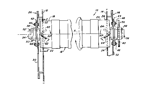
FIG. 1 is a top plan view of a bale-forming belt drive roll of a large round
baler
showing the roll located in respective circular holes provided in the right-
and left-hand side
walls of the baling chamber.
FIG. 2 is a vertical sectional view taken along line 2 - 2 of FIG. 1.
Descrj~tion of the Preferred Embodiment
Preliminarily, it should be noted that the terms "right-hand" and "left-hand"
are made
from the view point of an observer standing behind the implement and facing in
the forward
direction of travel.
Referring now to the drawings, there is shown (FIG. 1) a portion of a baling
chamber
10 of a large round baler, the chamber 10 including right- and left-hand side
walls or side
sheets 12 and 14, respectively. A bale-forming belt drive roll 16 extends
between the side
walls 12 and 14 and includes right- and left-hand cylindrical end sections 18
and 20 that
respectively extend through axially aligned circular holes 22 and 24 provided
in the side
walls 12 and 14.
Right- and left-hand bearing support structures 26 and 28 are respectively
fixed to
outer surfaces of the side walls 12 and 14 and include respective support
plates 30 and 32
disposed in parallel relationship to the walls 12 and 14. The roll 16 includes
right- and left-
hand shaft end sections 34 and 36, respectively, that are received in right-
and left-hand
bearings 38 and 40 that are pressed into right- and left-hand pairs of bearing
flanges 42 and
44, the pair of flanges 42 being secured to the support plate 30 by bolts 46,
and the pair of
flanges 44 being secured to the support plate 32 by bolts 48. Located outboard
of the pair
of bearing flanges 42 are a pair of washers 50 followed by a retaining pin 52,
and located
outboard of the pair of bearing flanges 44 is a washer 54 followed by a drive
sprocket 56
and a retaining pin 58.
As best seen in FIG. 2, a clearance gap 60 is defined between the right-hand
cylindrical end section 18 of the drive roll 16 and the perimeter of the
circular hole 22, it to
be understood that a similar clearance gap is defined between the left-had
cylindrical end
section 20 and the perimeter of the circular hole 24 in the left-hand side
wall 14. In order to
accommodate for manufacturing inaccuracies in the roundness of the roll 16
and/or
placement of the roll relative to the center of the hole 22, the gap 60 in the
preferred
embodiment is sized to be 1/4° + 1/16".
2

CA 02277517 1999-07-12
Up to this point, the structure described is more or less conventional. It is
to be
understood that while a drive roll is disclosed, the invention described below
would find utility
with any other bale-forming belt support roll which extends through the side
sheets or, even
with rolls used in other crop processing machines which would use rolls in an
environment
where they come into contact with crop materials that might find its way
through clearance
gaps in the side sheets.
Welded to diametrically opposite locations of the cylindrical sections 18 and
20 of the
roll 16 are right- and left-hand pairs of wipers or deflectors 62 and 64 that
respectively
extend into the clearance gap 60 provided in the right-hand wall 12 and into
the clearance
gap formed between the left-hand roll section 20 and the perimeter of the hole
24 in the left-
hand side wall 14. The wipers 62 and 64 are each angled relative to the axis A
of the roll 16
and are disposed such that they tend to move crop material away from the side
walls 12 and
14. It has been found that the wipers 62 are particularly effective in moving
crop material
inwardly if they are angled from between 30° to 60° relative to
the roller axis A. In the
preferred embodiment, the wipers 62 and 64 extend radially beyond the surfaces
of the
cylindrical sections 18 and 20 by a distance approximately equal to 3/16".
While the wipers
62 and 64 could take many forms, including being made of weld material, they
are
preferably constructed of wire or cylindrical rod or bar stock welded to the
roll 16, with the
weld being applied to the trailing side of the wiper so that a fairly smooth
leading edge is
presented to the crop material being wiped away. Also, it is to be noted that
the wipers 62
and 64 work well if their outer ends extend so as to be approximately even
with the opposite
ends of the roller 16 and if their inner ends are located just inboard of the
side sheets 12 and
14. The inner ends must be located far enough inwardly from the side sheets 12
and 14 to
keep the area clear but not so much as to encourage crop wrappage around the
end of the
roll. It is also important to keep the distance between the inner ends of the
wipers 62 and
64 and the side sheets 12 and 14 relatively small in order to minimize or
prevent contact
befinreen the wipers and the adjacent bale-forming belts, which normally
operate in close
proximity to the side walls 12 and 14. A distance of 5 mm. has been found to
work
satisfactorily. Further, it is noted that while a pair of wipers are disclosed
at each of the
opposite ends of the roll 16, it has been found that a single wiper will also
be effective in
keeping crop material from passing through and/or wedging in the gap defined
between the
boundary of the roll cylindrical section 18 and the side sheet hole 22, and
between the
3

CA 02277517 1999-07-12
boundary of the cylindrical roll section 20 and the side sheet hole 24.
The operation of the invention is thought to be clear from the foregoing
description.
Suffice it to say that, as the drive roll 16 rotates, the wipers 62 and 64,
respectively, engage
crop material in the vicinity of the gap 60 and the corresponding gap at the
opposite side of
the baling chamber, and move this crop material inwardly so that it does not
pass through
the gaps.
4

Representative Drawing
A single figure which represents the drawing illustrating the invention.
Administrative Status

2024-08-01:As part of the Next Generation Patents (NGP) transition, the Canadian Patents Database (CPD) now contains a more detailed Event History, which replicates the Event Log of our new back-office solution.

Please note that "Inactive:" events refers to events no longer in use in our new back-office solution.

For a clearer understanding of the status of the application/patent presented on this page, the site Disclaimer , as well as the definitions for Patent , Event History , Maintenance Fee  and Payment History  should be consulted.

Event History

Description Date
Time Limit for Reversal Expired 2016-07-12
Letter Sent 2015-07-13
Grant by Issuance 2003-11-25
Inactive: Cover page published 2003-11-24
Inactive: Final fee received 2003-08-27
Pre-grant 2003-08-27
Inactive: Delete abandonment 2003-08-14
Inactive: Office letter 2003-08-14
Deemed Abandoned - Failure to Respond to Maintenance Fee Notice 2003-07-14
Notice of Allowance is Issued 2003-03-03
Letter Sent 2003-03-03
Notice of Allowance is Issued 2003-03-03
Inactive: Approved for allowance (AFA) 2003-02-19
Amendment Received - Voluntary Amendment 2002-10-09
Inactive: S.30(2) Rules - Examiner requisition 2002-04-22
Application Published (Open to Public Inspection) 2000-05-03
Inactive: Cover page published 2000-05-02
Inactive: First IPC assigned 1999-09-01
Inactive: IPC assigned 1999-09-01
Inactive: Filing certificate - RFE (English) 1999-08-18
Filing Requirements Determined Compliant 1999-08-18
Letter Sent 1999-08-18
Application Received - Regular National 1999-08-17
Request for Examination Requirements Determined Compliant 1999-07-12
All Requirements for Examination Determined Compliant 1999-07-12

Abandonment History

Abandonment Date Reason Reinstatement Date
2003-07-14

Maintenance Fee

The last payment was received on 2003-07-11

Note : If the full payment has not been received on or before the date indicated, a further fee may be required which may be one of the following

  • the reinstatement fee;
  • the late payment fee; or
  • additional fee to reverse deemed expiry.

Please refer to the CIPO Patent Fees web page to see all current fee amounts.

Owners on Record

Note: Records showing the ownership history in alphabetical order.

Current Owners on Record
DEERE & COMPANY
Past Owners on Record
HENRY DENNIS ANSTEY
Past Owners that do not appear in the "Owners on Record" listing will appear in other documentation within the application.
Documents

To view selected files, please enter reCAPTCHA code :


To view images, click a link in the Document Description column. To download the documents, select one or more checkboxes in the first column and then click the "Download Selected in PDF format (Zip Archive)" or the "Download Selected as Single PDF" button.

List of published and non-published patent-specific documents on the CPD .

If you have any difficulty accessing content, you can call the Client Service Centre at 1-866-997-1936 or send them an e-mail at CIPO Client Service Centre.


Document
Description 
Date
(yyyy-mm-dd) 
Number of pages   Size of Image (KB) 
Representative drawing 2000-04-28 1 10
Cover Page 2003-10-22 1 44
Drawings 1999-07-12 1 29
Cover Page 2000-04-28 1 44
Claims 2002-10-09 1 53
Abstract 1999-07-12 1 20
Description 1999-07-12 4 190
Claims 1999-07-12 1 55
Courtesy - Certificate of registration (related document(s)) 1999-08-18 1 139
Filing Certificate (English) 1999-08-18 1 175
Reminder of maintenance fee due 2001-03-13 1 112
Commissioner's Notice - Application Found Allowable 2003-03-03 1 160
Maintenance Fee Notice 2015-08-24 1 170
Correspondence 2003-08-14 1 14
Correspondence 2003-08-27 1 26