Language selection

Search

Patent 2277672 Summary

Third-party information liability

Some of the information on this Web page has been provided by external sources. The Government of Canada is not responsible for the accuracy, reliability or currency of the information supplied by external sources. Users wishing to rely upon this information should consult directly with the source of the information. Content provided by external sources is not subject to official languages, privacy and accessibility requirements.

Claims and Abstract availability

Any discrepancies in the text and image of the Claims and Abstract are due to differing posting times. Text of the Claims and Abstract are posted:

  • At the time the application is open to public inspection;
  • At the time of issue of the patent (grant).
(12) Patent Application: (11) CA 2277672
(54) English Title: UNITARY PHOTO-ELECTRICAL COMPONENT
(54) French Title: COMPOSANTE UNITAIRE PHOTO-ELECTRIQUE
Status: Deemed Abandoned and Beyond the Period of Reinstatement - Pending Response to Notice of Disregarded Communication
Bibliographic Data
(51) International Patent Classification (IPC):
  • G06F 3/0354 (2013.01)
  • G02B 26/08 (2006.01)
(72) Inventors :
  • CHIN, KAY (Taiwan, Province of China)
  • LIANG, ANDREW (Taiwan, Province of China)
(73) Owners :
  • UNITY OPTO TECHNOLOGY CO., LTD.
(71) Applicants :
  • UNITY OPTO TECHNOLOGY CO., LTD. (Taiwan, Province of China)
(74) Agent: RICHES, MCKENZIE & HERBERT LLP
(74) Associate agent:
(45) Issued:
(22) Filed Date: 1999-07-14
(41) Open to Public Inspection: 2001-01-14
Examination requested: 1999-09-16
Availability of licence: N/A
Dedicated to the Public: N/A
(25) Language of filing: English

Patent Cooperation Treaty (PCT): No

(30) Application Priority Data: None

Abstracts

English Abstract


The present invention relates to an improved structure of a shield used in a
computer mouse. The shield includes a generating part and a receiving part
which are
formed by integration and arranged linearly for constructing the reflecting
shield for
the mouse. To make the manual work for inserting the shield into the circuit
board of
the mouse can be done by just one action of composition to avoid the time of
actions
of repeatedly inserting electrical elements into the circuit board and to
reduce the
production cost.


Claims

Note: Claims are shown in the official language in which they were submitted.

WHAT IS CLAIMED IS:
1. An improved structure of a light shield using reflecting composite device
in a side
of a smooth roller of a mouse comprising:
an emitting part, and
an receiving part, wherein the said emitting part and the said receiving part
are
formed by integration and. arranged linearly to make a light generated from
the said
emitting part be incident to the said smooth roller and reflected to and
received by the
said receiving part for constructing a reflecting composite device.
-4-

Description

Note: Descriptions are shown in the official language in which they were submitted.


CA 02277672 1999-07-14
IMPROVED STRUCTURE OF A SHIELD
FIELD OF THE INVENTION:
The present invention relates to an improved structure of a shield used in a
mouse, and, more particularly to an improved structure of a shield used in a
mouse
with a design of a shield which is formed by integration for reducing the
production
cost and composition cost, and for decreasing times of inserting slotting
attachments.
BACKGROUND OF THE INVENTION:
The mouse is an important periphery instrument of the computer, and, normally,
the positioning pointer o:f the mouse is using the semi-optical type. As shown
in FIG.
1, the structure of the ordinary mouse 10 uses the trackball 11 as the sliding
and
moving element. One smooth roller 12 of one pivot axle 121 is located in the
longitudinal direction of the trackball 11, the other smooth roller 12 of the
other pivot
axle 121 is located in the latitudinal directions of the trackball 11, and a
plurality of
toothed wheels 122 are located around peripheries of the two smooth roller 12.
There
is a distance 123 between two toothed wheels 122, and there are a receiver 21
and a
emitter 22 (such as the photo diode and the light emitting diode) respectively
located
on the circuit board 20 corresponding to both sides of the toothed wheel 122.
The trackball 11 slides and moves to make the two pivot axles 121 rotate, and
the
two rotating pivot axles 121 would make the smooth roller 12 rotate between
the
receiver 21 and the emitter 22. However, while a light generated from the
emitter 22 is
incident to a position of the toothed wheel 122, the light would be shielded
and the
receiver 21 can not receive any light. While the light is incident to the
distance 123
between two toothed wheels 122, the receiver 22 can easily receive the light.
By
shielding and receiving the light, the low level of the signal and the high
level of the
signal are formed to produce the corresponding coordinate signals of the X and
Y axes
of the monitor to make the pointer of the mouse 10 on the monitor move with
motions

CA 02277672 1999-07-14
of the mouse 10 according to coordinate signals.
However, during the assembly processes of the mouse 10, the all part including
electrical elements and opto-electronics of the circuit board 20 are manually
inserted,
and the total number of the opto-electronics of the aforesaid X and Y axes are
four,
two for emitter 22 and two for receiver 21. That is, the operator would
manually insert
the opto-electronics four times, and each one should be inserted in the same
angle to
make the receiving path and the generating path uniform. However, by using the
manually inserted method in enormously producing products, the yield is lower
and
the sensibility of the mouse is degrading. Thus, the coupled way composed by
the
emitter and the receiver in the real matlufacturing line would increase the
production
hours of product, make the composition of the mouse more difficult, and
degrade the
yield, so there are improvements needed to improve the aforesaid problems.
SUMMARY OF THE INVENTION:
Accordingly, an object of the present invention is to provide an improved
structure of a shield used in the mouse with a emitting part and a receiving
part which
are formed by integration and arranged linearly to form the reflecting
composite
device for the mouse to make the manual work for inserting the reflecting
composite
device into the circuit board of the mouse be done by just one action of
composition to
avoid the time of actions of repeatedly inserting emitter and receiver into
the circuit
board and to reduce the production cost.
BRIEF DESCRIPTION OF THE I~NGS:
The above and other objects, features and other advantage of the present
invention will be more clearly understood from the following detailed
description
taken in conjunction with the accompanying drawings, in which:
FIG. 1 is a composition view which illustrates the composition of the shield
of
the ordinary mouse;
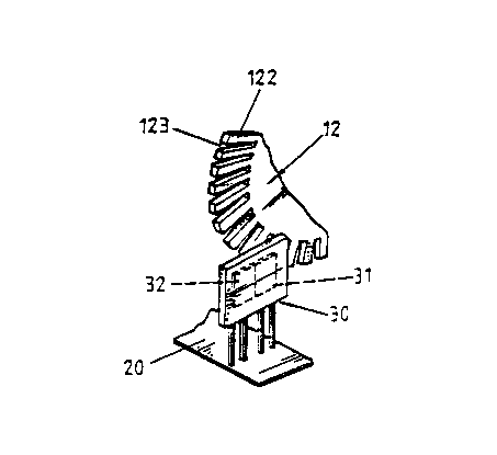
FIG. 2 is a cubical view which illustrates a shield of the present invention;
FIG. 3 is a composition view which illustrates FIG. 2 composed with the smooth
roller;
FIG. 4 is a action diagram view which illustrates FIG. 3 without the receiving
action; and
FIG. 5 is a action diagram view which illustrates FIG. 3 with the receiving
action.
D_ ETAILED DESCRIPTION OF THE PREFERRED EMBODtM~w t
As shown in FIG. 2 and 3, the reflecting composite device 30 of the present
_2_

CA 02277672 1999-07-14
invention includes a emitting part 31 and a receiving part 32 which are formed
by
integration and arranged linearly to form the so called reflecting composite
device.
The reflecting composite device 30 is composed in a side of the smooth roller
12
corresponding to a position of the toothed wheel 122 of the periphery of the
smooth
roller 12. While the mouse 12 moves, the smooth roller 12 would rotate with
the
rolling trackball 11.
Referring to FIG. 4, if the distance 123 between toothed wheels 122 is rotated
to
meet the generating part 31, the light generated from the generating part 31
goes
through the distance 123, and the receiving part 32 can not receive any
signals.
As shown in FIG. 5, if the toothed wheels is rotated to meet the generating
part
31, the light generated from the generating part 31 is incident to the toothed
wheel 122,
reflected by the toothed wheel 122, and received by the receiving part 32. By
receiving the reflected light and without receiving the change of the signal,
the high
level of the signal and the low level of the signal are formed to produce the
corresponding coordinate signals of the X and Y axes of the monitor to make
the
pointer of the mouse 10 on the monitor move with motions of the mouse 10
according
to coordinate signals.
The light shield with an improved structure of the present invention is formed
by
integration, is easily made, and has lower production cost. As for the
embodiment of
the aforesaid reflected composite device, it is easier to insert the opto
parts compared
with the ordinary mouse, and once the opto-electronics are inserted into the
circuit
board, the angle and latitude of the composition of the shield compared with
the
ordinary shield are not needed to be adjusted for reducing working hours of
the
product and the production cost, and for improving the sensibility of judging
the
rotation and motion of the mouse to make the mouse have the real improvement.
However, the design of the improved structure of the light shield of the
present
invention has improvements in efficiency and progression.
The present invention has been described hitherto with exemplary preferred
embodiments. However, it is to be understood that the scope of the present
invention
need not be limited to the disclosed preferred embodiments. On the contrary,
it is
intended to cover various modifications and similar arrangements with the
scope
defined in the following appended claims. The scope of the claims should be
accorded
the broadest interpretation so as to encompass all such modifications and
similar
arrangements.
-3-

Representative Drawing
A single figure which represents the drawing illustrating the invention.
Administrative Status

2024-08-01:As part of the Next Generation Patents (NGP) transition, the Canadian Patents Database (CPD) now contains a more detailed Event History, which replicates the Event Log of our new back-office solution.

Please note that "Inactive:" events refers to events no longer in use in our new back-office solution.

For a clearer understanding of the status of the application/patent presented on this page, the site Disclaimer , as well as the definitions for Patent , Event History , Maintenance Fee  and Payment History  should be consulted.

Event History

Description Date
Inactive: IPC assigned 2013-02-01
Inactive: First IPC assigned 2013-02-01
Inactive: IPC assigned 2013-02-01
Inactive: IPC expired 2013-01-01
Inactive: IPC removed 2012-12-31
Inactive: IPC deactivated 2011-07-29
Inactive: First IPC derived 2006-03-12
Inactive: IPC from MCD 2006-03-12
Application Not Reinstated by Deadline 2004-07-14
Time Limit for Reversal Expired 2004-07-14
Deemed Abandoned - Conditions for Grant Determined Not Compliant 2003-12-01
Deemed Abandoned - Failure to Respond to Maintenance Fee Notice 2003-07-14
Notice of Allowance is Issued 2003-05-29
Letter Sent 2003-05-29
Notice of Allowance is Issued 2003-05-29
Inactive: Approved for allowance (AFA) 2003-05-02
Amendment Received - Voluntary Amendment 2002-05-13
Inactive: S.30(2) Rules - Examiner requisition 2002-01-21
Inactive: Cover page published 2001-01-14
Application Published (Open to Public Inspection) 2001-01-14
Letter Sent 2000-07-12
Inactive: Single transfer 2000-06-13
Inactive: Courtesy letter - Evidence 2000-06-01
Inactive: Single transfer 2000-04-25
Inactive: Application prosecuted on TS as of Log entry date 1999-10-06
Letter Sent 1999-10-06
Inactive: Status info is complete as of Log entry date 1999-10-06
Inactive: First IPC assigned 1999-09-17
Request for Examination Received 1999-09-16
Request for Examination Requirements Determined Compliant 1999-09-16
All Requirements for Examination Determined Compliant 1999-09-16
Inactive: Courtesy letter - Evidence 1999-08-24
Inactive: Filing certificate - No RFE (English) 1999-08-20
Filing Requirements Determined Compliant 1999-08-20
Application Received - Regular National 1999-08-19

Abandonment History

Abandonment Date Reason Reinstatement Date
2003-12-01
2003-07-14

Maintenance Fee

The last payment was received on 2001-06-08

Note : If the full payment has not been received on or before the date indicated, a further fee may be required which may be one of the following

  • the reinstatement fee;
  • the late payment fee; or
  • additional fee to reverse deemed expiry.

Please refer to the CIPO Patent Fees web page to see all current fee amounts.

Fee History

Fee Type Anniversary Year Due Date Paid Date
Application fee - small 1999-07-14
Registration of a document 1999-07-14
Request for examination - small 1999-09-16
MF (application, 2nd anniv.) - small 02 2001-07-16 2001-06-08
Owners on Record

Note: Records showing the ownership history in alphabetical order.

Current Owners on Record
UNITY OPTO TECHNOLOGY CO., LTD.
Past Owners on Record
ANDREW LIANG
KAY CHIN
Past Owners that do not appear in the "Owners on Record" listing will appear in other documentation within the application.
Documents

To view selected files, please enter reCAPTCHA code :


To view images, click a link in the Document Description column. To download the documents, select one or more checkboxes in the first column and then click the "Download Selected in PDF format (Zip Archive)" or the "Download Selected as Single PDF" button.

List of published and non-published patent-specific documents on the CPD .

If you have any difficulty accessing content, you can call the Client Service Centre at 1-866-997-1936 or send them an e-mail at CIPO Client Service Centre.


Document
Description 
Date
(yyyy-mm-dd) 
Number of pages   Size of Image (KB) 
Representative drawing 2001-01-03 1 7
Description 2002-05-13 5 226
Claims 2002-05-13 2 45
Drawings 2002-05-13 2 37
Abstract 2002-05-13 1 19
Description 1999-07-14 3 166
Abstract 1999-07-14 1 15
Claims 1999-07-14 1 14
Drawings 1999-07-14 2 35
Cover Page 2001-01-03 1 29
Filing Certificate (English) 1999-08-20 1 175
Acknowledgement of Request for Examination 1999-10-06 1 178
Courtesy - Certificate of registration (related document(s)) 2000-07-12 1 115
Reminder of maintenance fee due 2001-03-15 1 112
Commissioner's Notice - Application Found Allowable 2003-05-29 1 160
Courtesy - Abandonment Letter (Maintenance Fee) 2003-08-11 1 176
Courtesy - Abandonment Letter (NOA) 2004-02-09 1 168
Correspondence 1999-08-20 1 14
Correspondence 2000-06-01 1 11
Fees 2001-06-08 1 39