Note: Descriptions are shown in the official language in which they were submitted.
. . . .,. ~.,: ~. _ t m.~ ~ ,.
CA 02278261 1999-07-20
1
STRUCTURE OF DETACHABLE AUXILIARY LENSES WITH MAGNETS
BACKGOUND OF THE INVENTION
1. Field of the invention
The present invention relates in general to eyeglasses and auxiliay
lenses capable of being detachably coupled to eyeglasses. More
particularly, the present invention relates to means with which auxi liary
lenses are attached to eyeglasses. And still more particularly, the
present invention proposes a structure for the auxiliary lenses to form
a secure connection when attached to the eyeglasses, without worry of
falling apart from the eyeglasses due to slight change of shape of the
frame of the eyeglasses when the eyeglasses fi t on a human wearer's head.
2. Description of the related art
In the pas t various means have been ut i 1 i zed to secure auxi 1 i ary
lenses
to eyeglasses. One of them is clipping device, which is permanently
attached to the auxiliary lenses. The clipping device fits around the
frames of the eyeglasses to clip the auxiliary lenses to the eyeglasses.
However, the clipping devices make the eyeglasses look unattractive.
Another means for securing auxiliary lenses to eyeglasses is to use
magnetic material. This is currently a popular way to secure auxiliary
lenses to eyeglasses, and several devices have been proposed and patented,
including Magnetic Means For Securing Auxiliary Lenses To Eyeglasses,
patented by U.S.Patent and Trademark Office wi th patent number 5,416,537,
and Detachable Sunglasses With Magnets, also patented by U.S.Patent and
Trademark Office with patent number 5,642,177.
CA 02278261 1999-07-20
2
According to the above mentioned patents, numbered 5,416,537 and
5,642,177, referring to Figs. 6 and 7, magnets I01 are fixed to two end
portions of rim 10 of the eyeglasses while magnets 20I are fixed to two
end portions of rim 20 of the templeless auxiliary sunglasses; thus, the
templeless auxi liary sunglasses can be secured to the eyeglasses by means
of the magnets 201, 101 attracting each other to form a bond.
Another device proposed for the same purpose is a patent application
with P'CT, with application number WO 90109611. Referring to Fig. 8, a
magnet 302 is provided on bridge 301 of rim 30 of the eyeglasses while
a second magnet 402 is mounted on bridge 401 of rim 40 of the templeless
sunglasses; thus the templeless sunglasses can be secured to the
eyeglasses by means of the magnets 402,302 attracting each other to form
a bond.
However, through experience, it is found that the temples of the
eyeglasses would broaden when fitting on a wearer's head, causing the end
portions of the rim to angularly turn. The turning of the end portions
of the rim would change the position of the magnets mounted thereon,
resulting in loss of close contact between the magnets of the templeless
sunglasses and the magnets of the eyeglasses and consequently the
sunglasses fall from the eyeglasses under extreme conditions.
As for the sunglasses with magnets mounted on the bridge, the bond
is found to be too weak and the sunglasses would easily turn at an angle
from the desired position.
To overcome the disadvantages of the above mentioned means, other
means have been proposed, including U.S.Patents Auxiliary Lenses For
CA 02278261 1999-07-20
3
Eyeglasses, patent numbers 5,568,207 and 5,737,054.
According to U.S.Patent unmbered 5,568,207, referring to Fig. 10,
magnets 503 are mounted on endpieces 502 of rim 50 of the eyeglasses, the
endpieces 502 being provided to connect temples 501. Second magnets 602
are mounted on supporting end portions 641 of templeless sunglasses 60
so that the templeless sunglasses 60 can be secured to the eyeglasses by
means of the bond between the magnets 503 and 602, the supporting end
portions 601 resting on the endpieces 502 of the rim 50 to provide a stable
support for the templeless sunglasses 60, as shown in Fig. 11.
As for U.S.patent number 5,737,054, Auxiliary Lenses For Eyeglasses,
referring to Fig. 12, a magnet 702 is mounted on a bridge 701 of the
eyeglasses 70 while a second magnet 803 is mounted on bottom portion of
a protrusion 802 provided above a bridge of the templeless eyeglasses 80;
thus, the templeless sunglasses can be secured to the eyeglasses by means
of bond between the magnets 803 and 702 attracting each other.
Moreover, the inventor of the present invention proposed a means for
securing auxiliary lenses to eyeglasses, which was filed at U.S.Patent
and Trademark Office on October 28, 1997 with application number
08/959,486 referring to Fig. 13, magnets 901 are mounted on endpieces 902
of eyeglasses 90 in a way that recesses 903 are formed on the endpieces
902. A templeless eyeglasses 905 is provided, having extending portions
906 at two ends and magnets 904 mounted on the extending portions 9U6 in
a way that the magnets 904 each forms a protrusion; thus, the templeless
sunglasses 905 can be coupled to the eyeglasses by means of bond between
the magnets 901 and 904 attracting each other, with the recesses 903
CA 02278261 1999-07-20
4
retaining the magnets 904 to strengthen the bond, as shown in Fig. 14.
The above mentioned three means provide a stabler and more secure
connection between the eyeglasses and the templeless sunglasses, however
the wearer has to put on the templeless sunglasses from above the
eyeglasses fitting on hislher head due to presence of the extending
portions 906 in Fig. 13, the protrusion 802 in Fig. 12, and the supporting
end portions 601 in Figs. 10 and 11. This is different from the way the
wearer is used to when putting on the templeless sunglasses, i.e. from
ahead of the eyeglasses. So it is not very convenient in using securing
means of this kind.
SUMMARY
A detachable auxiliary sunglasses with magnets of the present
invention is devised to be capable of detachably fitting on a primary
eyeglasses. The auxiliary sunglasses are templeless and the magnets are
mounted on turning members of the sunglasses at two end portions of the
rim, the turning members being capable of pivotting on the end portions.
The auxiliary sunglasses provides a protection to a wearer from
vision-damaging elements of sunlight when fitting on a primary eyeglasses
worn by the wearer; the primary eyeglasses have magnets in positions
corresponding to the positions of the magnets of the auxiliary sunglasses
so that the sunglasses can be secured to the primary eyeglasses by means
of bond between the magnets attracting each other.
The magnets of the auxiliary sunglasses, being capable of pivoting
CA 02278261 1999-07-20
S
on the end portions along with the turning members, can maintain a stable
and close contact wi th magnets of the primary eyeglasses even i f posi tion
of the magnets of the primary eyeglasses changes for an angle due to change
of shape of the primary eyeglasses through wearing
BRIEF DESCRIPTION OF THE DRAWINGS
The present invent ion will be better understoodwith reference to the
accompanying drawings, wherein:
Fig. 1 is an exploded perspective view of an detachable auxiliary
lenses and an associated eyeglasses of the present invention.
Fig. 2 is a top view of the detachable auxiliary lenses coupled to
an associated eyeglasses according to the present invention.
Fig. 3 is a top view of a hinge of the detachable auxiliary lenses
of the present invention, with the magnet thereon secured to a respective
magnet of the associated eyeglasses.
Fig. 4 is a top view showing the detachable auxiliary lenses of the
present invention under change of posi tion of the temple of the associated
eyeglasses;
Fig. 5 is an enlarged fragmentary view of Fig. 4.
Fig. 6 is a top view of a heretofore known auxiliary lenses and the
associated eyeglasses as described in the Background.
Fig. 7 is a perspective view of heretofore known auxi liary lenses and
the associated eyeglasses as described in the Background.
Fig. 8 is a top view of a third heretofore known auxiliary lenses and
CA 02278261 1999-07-20
6
the associated eyeglasses as described in the Background.
Fig. 9 is a top view showing the connection between the auxiliary
lenses and its associated eyeglasses when distance between the temples
are broadened.
Fig. 10 is a top view of a fourth heretofore known auxiliary lenses
and the associated eyeglasses as described in the Background.
Fig. 11 is an enlarged fragmentary section view of Fig. 10.
Fig. 12 is a top view of a fifth heretofore known auxiliary lenses
and the associated eyeglasses as described in the Background.
Fig. 13 is a perspective of a sixth heretofore known auxiliary lenses
and the associated eyeglasses as described in the Background.
Fig. 14 is a section view of the sixth auxi Nary lenses and associated
eyeglasses of Fig. 13.
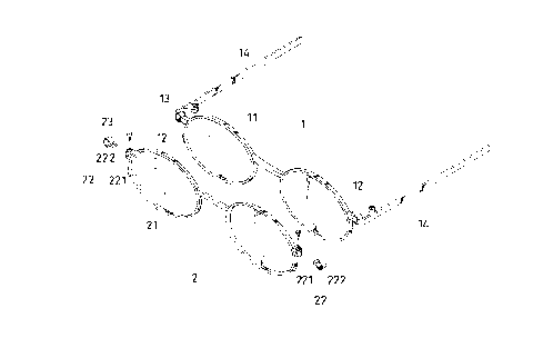
is DETAILED DESCRIPTION OF THE PRIEFERRIED Eh~ODIMENTS
A detachable auxiliary lenses with magnets of the present invention,
referring to Fig. 1, includes a rim 2, sunglasses 21 mounted within the
rim 2, endpieces 221 at two end portions of the rim 2, which endpieces
221 are formed such that they can be each pivotally connected with a
respective turning member 222 to form a hinge ( denoted with numeral 22
as a whole ). A magnet 23 is mounted within a respective turning member
222.
A pair eyeglasses are provided, including a rim l, lenses 11 mounted
2s within the rim 1, connecting portions 12 at two end portions of the rim
CA 02278261 1999-07-20
7
1, magnets 13 each mounted on a respective one of the connecting portions
12, and temples 14 pivotally connected to the connecting portions 12;
magnets 23 of the templeless sunglasses are arranged in positions
corresponding with positions of the magnets 13 of the eyeglasses. Thus,
the templeless auxiliary sunglasses can be secured to the eyeglasses by
means of a bond between the magnets 13 and 23 attracting each other.
Moreover, the hinges 22 at two end portions of the sunglasses permit the
turning members 222, within which the magnets 23 are mounted, to turn
according to the position of the magnets 13 connected with the magnets
23. Thus, when a wearer put on the eyeglasses with the auxiliary
sunglasses coupled thereto, the auxiliary sunglasses can be firmly secured
to the eyeglasses even if the magnets 13 turn at an angle due to broadening
of the distance between the temples 14 when the eyeglasses fi t on a wearer's
head.
From the above description, it can be understood that the magnets 23
pivotally connected to the auxiliary sunglasses can always have close
contact with the magnets 13 of the eyeglasses, no matter how the position
of the magnets 13 change due to wearing. Furthermore, the auxiliary
sunglasses can be put on the eyeglasses from ahead of the sunglasses worn
on the user's head, preserving a very convenient way of wearing.