Note: Descriptions are shown in the official language in which they were submitted.
CA 02278554 1999-07-22
WO 98/31307 PCT/IJS97/00938
-1-
STERIhE AD8E8IVE BANDAGE AND ASSOCIATED MET80DB
BACRGROQND OF T8E INDENTION
I. FIELD OF THE INVENTION
This invention relates generally to an apparatus for
enclosing a sterile device. More particularly, this
invention relates to a sterile adhesive bandage,
encapsulated in a protective covering. The protective
covering may be removed and the sterile bandage may be
applied by a user with just one hand without
contaminating any portion of the sterile bandage. This
invention also relates to the method and apparatus for
producing the sterile adhesive bandage contained in the
protective covering, wherein the bandage may be removed
from the protective covering and applied by the user with
one hand.
II. DISCUSSION OF THE RELATED ART
Over the years, continued refinements have been made
to dispensing bandages and other sterile devices. A
plurality of sterile devices are commonly contained in an
interconnected series of sterile packages. Removing each
sterile device from the package requires contact by the
user. Protective gloves may be worn during the removal
and handling of the sterile device thereby avoiding
contamination, however, the use of sterile gloves is
often times neither economical nor efficient.
Various delivery systems have been described that
assist the user in removing an individual sterile device
from the package with only one hand. The following
patents describe a delivery system that dispense the
sterile device, requiring only one hand by the user:
Haber, U.S. Pat. No. 4,733,797 (the '797 patent);
Goldstein, U.S. Pat. No. 4,807,753 (the '753 patent);
Moshel, U.S. Pat. No. 3,520,403 (the '403 patent); and
Cooper U.S. Pat. No. 1,827,354 (the '354 patent).
Although these disclosed delivery systems dispense the
sterile device, requiring only one hand, the user must
use two hands in the later application of the sterile
CA 02278554 1999-07-22
WO 98131307 PCT/US97/00938
-2-
device. Hence, there is a need for a packaged sterile
device that may be dispensed and applied with only one
hand.
A commonly packaged sterile device is an adhesive
bandage. The conventional bandage includes a gauze pad
attached to an adhesive coated bandage strip. When
applying the bandage to the desired surface, the user
removes the adhesive bandage from the sterile package,
contacting either the sterile gauze or a portion of the
adhesive strip. This contact either contaminates the
gauze pad or reduces the tactile adhesion of the adhesive
strip.
Taulbee, deceased et al., in U.S. Pat. No. 4,993,586
(the '586 patent), and Adams IV, U.S. Pat. No. 3,835,992
(the '992 patent) both disclose an adhesive bandage
dispensing package. Taulbee discloses an adhesive
bandage sandwiched between an upper and lower protective
strip. The adhesive side of the bandage is mounted
facing downward on the lower protective strip. One end
of the adhesive strip preferably attaches to a mounting
pad. The mounting pad facilitates removal of the bandage
from the lower protective strip, however, two hands are
required to remove the mounting pad from the adhesive
strip, and a portion of the sterile bandage must be
contacted by the user. Therefore, a need exists for a
sterile device, such as a bandage~that may be dispensed
and applied with one hand without contaminating any
portion of the sterile device.
Adams, IV, discloses a bandage dispensing package
similar to Taulbee, which dispenses a bandage from a
continuous roll. A similar mounting pad separates one
end of the adhesive strip from the lower protective
strip. In use, the user must use two hands to separate
the mounting pad from the adhesive strip. Hence, there
is a need for a bandage that may be dispensed and applied
with only one hand. The present invention overcomes
these and other disadvantages.
CA 02278554 1999-07-22
WO 98/31307 PCT/US97/00938
-3-
BOMMARY OF THE INVENTION
The purpose of the present invention is to provide a
bandage that may be applied without contaminating any
portion of the bandage. In the preferred embodiment, the
bandage can further be applied with a single hand without
contaminating any portion of the bandage. The bandage is
enclosed in a sealed sterile package, whereby the bandage
may be removed from the package and applied to a desired
surface with only one hand. The sterile package,
including the bandage, comprises a flexible strip, a
carrier member, a wound pad, a pull tab, and a release
backing.
The flexible strip has a coating of adhesive
deposited on at least the lower planar surface of the
strip. A wound pad is attached to the lower planar
surface of the strip and centered such that a portion of
the adhesive strip extends from each end of the wound
pad. The wound pad and strip are die cut in a
predetermined shape, thereby separating the wound pad and
strip into an outer surrounding frame and inner bandage.
The pull tab is further attached to a lower planar
surface of the outer surrounding frame, proximate an end
of the flexible strip.
The flexible strip, wound pad, and pull tab are
sandwiched between a carrier member and a release
backing. The carrier member has a light tack adhesive,
thereby attaching to an upper surface of both the bandage
and outer surrounding frame of the adhesive strip. The
release backing adheres to the lower surface of the
flexible, adhesive strip.
.. In the preferred embodiment, a plurality of bandages
and outer surrounding frames, each having a carrier
member attached thereto, are attached in series to a
continuous roll of release backing. The bandages may be
individually dispensed from the roll. As the bandage is
dispensed, the bandage, outer frame and carrier member
separate from the release backing.
CA 02278554 1999-07-22
WO 98/31307 PCT/US97/00938
-4-
The user centers the wound pad over the desired
location and presses the tab and an adjacent portion of
the adhesive strip against the desired surface. The
remaining portion of the adhesive strip is pressed
against the desired surface. By holding onto the pull
tab, the user avoids any contaminating contact with the
bandage, including cross-contamination of the upper
surface of the bandage. The pull tab is then pulled away
from the surface, separating the pull tab and outer frame
of the adhesive strip from the bandage. The outer frame
of the bandage and carrier member separates from the
bandage leaving the bandage affixed to the desired
surface. In this manner only one hand is required to
dispense the bandage and apply the bandage to the desired
surf ace .
During the manufacture of the continuous roll of
bandages a sheet of adhesive may be used to form in rows
and columns a plurality of interconnected bandages. The
columns of bandages formed on the sheet may be separated,
to thereby form a plurality of continuous rolls of
bandages.
In an alternate preferred embodiment, each bandage
and outer frame are attached to an independent release
backing. A plurality of these bandages may be indexed
and dispensed independently. The pull tab is not
attached to the release backing, which aids the user in
easily removing the release backing from the bandage and
outer frame.
In another alternate preferred embodiment the
flexible strip is constructed of a litmus paper,
eliminating the need for a wound pad. The litmus paper
may be removed from its package similar to the removal of
the bandage, thereby avoiding any contaminating contact
to the paper.
It is accordingly a principal object of the present
invention to provide a sterile adhesive bandage that may
be removed from its package and applied with a single
CA 02278554 1999-07-22
WO 98/31307 PCT/US97/00938
-5-
hand without any contaminating contact to the bandage s
adhesive strip or wound pad.
Another object of the present invention is to
provide a sterile litmus paper that may be removed from
its package without any contaminating contact to the
litmus strip.
Still a further object of the present invention is
to provide a method of manufacturing a sterile bandage
that may be dispensed and applied by the user without
contaminating the bandage.
Still another object of the present invention is to
provide a method for manufacturing a continuous roll of
interconnected bandages that may be separated
individually, dispensed, and applied by the user using
only one hand.
Still a further object of the present invention is
to provide a method of simultaneously manufacturing from
a web sheet of adhesive material, a plurality of
continuous rolls of bandages.
These and other objects, as well as these and other
features and advantages of the present invention will
become readily apparent to those skilled in the art from
a review of the following detailed description of the
preferred embodiment in conjunction with the accompanying
claims and drawings in which like numerals in the several
views refer to corresponding parts.
DESCRIPTION OF THE DRAWINGS
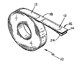
Figure 1 is a perspective view of a plurality of
interconnected bandages, forming a continuous roll of
bandages;
Figure 2 is a partial exploded perspective view of
interconnected bandages;
Figure 3 is a perspective view of a continuous roll
of bandages of the type shown in Figure 1 being
dispensed;
Figure 4 is a perspective view of a plurality of
individual indexed bandages;
CA 02278554 1999-07-22
WO 98/31307 PCT/US97/00938
- 6-
Figure 5 is an enlarged partial perspective view of
interconnected bandages having the release backing
partially removed;
Figure 6 is a perspective view of an individual
bandage being applied to a patient's wrist;
Figure 7 is a perspective view of an individual
bandage applied to a user's wrist;
Figure 8 is a bottom plan view of an inner bandage
removed from the outer surrounding frame and carrier
member;
Figure 9 is a perspective view, partially in block,
of the apparatus for manufacturing the bandage and its
package; and
Figure 10 is a flow diagram of the steps necessary
to manufacture a plurality of continuous rolls of
bandages roll of the type shown in Figure 1.
DETAILED DESCRIPTION OF THE PREFERRED EMBODIMENT
Referring first to Figures 1 and 2, there is shown
generally a continuous roll 10 of bandages 12. Each
bandage 12 consists generally of a flexible adhesive
strip 14, an outer surrounding frame 16, a carrier member
18, a wound pad 20, a pull tab 22, and a release backing
24.
The wound pad 20 and pull tab 22 are attached to the
lower planar surface 28 of the adhesive strip 14 (see
Figures 2 and 8). The bandage 12 is die cut from the
adhesive strip 14 and separated from the outer
surrounding frame 16. A carrier member 18 is attached to
the upper planar surface 26 of the bandage 12 and outer
surrounding frame 16. For illustrative purposes, the die
cut defining the shape of the bandage 12 is depicted as
visible through the carrier member 18. Those skilled in
the art will recognize that the carrier member may be
manufactured from an opaque or transparent material. The
lower planar surface 28 of the bandage 12 and outer
surrounding frame 16 are attached a continuous roll of
CA 02278554 1999-07-22
WO 98/31307 PCT/US97/00938
release backing 24, thereby forming a continuous roll 10
of interconnected bandages 12.
The flexible strip 14 has an adhesive, suited to
medical applications, bonded to the lower planar surface
28 of the strip. Without limitation, the flexible strip
14 may be of a transparent or opaque: vinyl, woven
fabric, non-woven fabric, or polyester material. An
adhesive may be formed on the upper surface 26 of the
flexible strip 14 or the lower surface 30 of the carrier
member 18. In the preferred embodiment, an adhesive is
bonded to the lower surface 30 of the carrier member 18.
The adhesive is formulated so that when the bandage 12 is
removed from the carrier member 18, the adhesive remains
on the carrier member 18. Without limitation, this
adhesive is a nontransferable light tack adhesive
commonly known in the industry as high tack/low tack
adhesive, and is available from Minnesota Mining and
Manufacturing, Inc., St. Paul, Minnesota. The release
backing 24 is preferably manufactured from a polymer,
easily removable from the flexible strip s adhesive.
The pull tab 22 does not adhere to the release
backing 24, allowing the user to easily remove the
release backing from an individual bandage 12. When the
bandage 12 and outer surrounding frame 16 are sandwiched
between the carrier member 18 and the release backing 24,
an air tight seal is formed, whereby the wound pad 20 and
bandage 12 remain sterile.
Referring next to Figure 3, a continuous roll of
bandages 10 is positioned within a dispenser 32, whereby
the bandage 12 may be dispensed with only one hand. The
bandage 12 is shown partially dispensed. As the user
pulls on the pull tab 22, the bandage 12, outer
surrounding frame 16, and carrier member 18, together,
exit an opening 34 in the dispenser while the release
backing 24 separates from the flexible adhesive strip 14
and is guided away through a guide channel 36. Each
bandage 12, outer surrounding frame 16 and carrier member
CA 02278554 1999-07-22
WO 98/31307 PCT/US97/00938
_g_
18 are separated from the continuous roll 10 in a similar
fashion.
An alternate preferred embodiment is shown in Figure
4. Each bandage 12 and outer frame 16 are attached to an
independent strip of release backing 24. A plurality of
bandages 12 are shown indexed and dispensed
independently, whereby the arrows aligned with the
longitudinal axis of the bandage 12 indicate the
dispensing motion and direction. When the user dispenses
an individually indexed bandage 12, the pull tab 22
assists the user in easily removing the release backing
24 from the bandage 12 and outer frame 16.
Figures 5-7 further illustrate how the bandage 12 is
separated from the release backing 24, carrier member 18
and outer frame 16. The release backing 24 is first
removed from the lower planar surface 28 of the bandage
12 and outer surrounding frame 16 (see Figure 5). The
user then aligns the wound pad 20 over the desired
surface and presses the adhesive strip 14 against the
desired surface. The user then pulls the pull tab 22
away from the desired surface, towards the other end of
the adhesive strip 14.
The bandage 12 separates from the carrier member 18,
while adhering to the desired surface. The outer
surrounding frame 16 remains attached to the carrier
member 18, when the pull tab 22 is used to peel the outer
frame 16 and carrier member 18 from the desired surface.
In this manner only one hand is required to dispense and
apply the bandage 12 to a desired surface.
Referring next to Figures 9 and 10, an apparatus 36
for manufacturing a plurality of continuous rolls of
bandages 10 is generally shown and described. The
apparatus 36 includes several stations that perform
various functions on an adhesive strip 14 or web roll 38
being continuously fed therethrough, thereby forming
continuous rolls of bandages 10.
CA 02278554 1999-07-22
WO 98/31307 PCT/LTS97/00938
_g_
After obtaining a sheet or web roll 38 of material
having adhesive deposited on at least one planar surface
(see block 40), the continuous web roll 38 is fed past a
first station 42, wherein a vacuum placing system 44, of
known construction, systematically places strips of wound
pad 20 in spaced relation on the adhesive surface of the
web roll 38 (see block 46). In an alternate preferred
embodiment, individual wound pads 20 are systematically
placed on the adhesive surface of the web roll 38 and
arranged in island placement. When the wound pad 20 is
arranged on the web by island placement, a portion of the
adhesive strip extends from the wound pad 20 from all
sides of the wound pad.
The web roll 38 continues forward to a second
station 48, where strips of pull tab 22 are
systematically positioned and attached to the web roll
38. The pull tab 22 is positioned on the web roll 38 a
predetermined distance from each wound pad 20 (see block
50). Of course, an additional pull tab 22 may be
attached and positioned a predetermined distance from
each wound pad 20, such that a pull tab 22 will be
attached at each end of the adhesive strip 14.
Those skilled in the art will recognize that the
vacuum placing system 44 may either simultaneously or
individually place the wound pad 2o and pull tab 22 on
the adhesive surface of the web roll 38. The vacuum
placing system as shown, has two independent vacuum
plates, however, those skilled in the art will recognize
that one vacuum plate may be used to place the wound pad
20 and pull tab 22 on the adhesive surface of the web
roll 28 in spaced relation, either simultaneously or
independently.
Guide rollers 52 direct the web roll 38 over a sheet
roll of release backing 24, whereby the release backing
24 is pressed against the lower adhesive surface 14 of
the adhesive strip 14 or web roll 38. The release
backing 24 is thereby attached to the web roll 38,
CA 02278554 1999-07-22
WO 98/31307 PCTIUS97/00938
-10-
sealably covering the wound pad 20 and pull tab 22 (see
block). A first die 56 of known construction having a
predetermined shape die cut/kiss cuts the wound pad 20
and web roll 22 to the release backing into a plurality
of bandages having predetermined shapes (see block 58).
The carrier member 18 is guided into contact with
the web roll 38 and release backing 24 by guide roller 60
(see block 62). The carrier member 18 adheres to the
upper surface 26 of the web roll 38, thereby sealing the
web roll 38 between the carrier member 18 and the release
backing 24. A second die-cutter 64 of known construction
die cut/kiss cuts to the release backing the web roll and
carrier member along their widths, thereby defining rows
of bandage strips (see block 66). Finally, as the
compressed web roll 38, carrier member 18 and release
backing 24 are rolled onto a spool 68, a slitter 72 slits
the compressed web roll 38, carrier member 18 and release
backing 24 along their longitudinal axis, thereby forming
several continuous rolls of interconnected bandages 10
(see block 70). Those skilled in the art will recognize
that the various stations may be connected to a central
frame 74 or connected to several integral frames. Once a
desired length of the continuous roll is rolled onto the
spool 68 which rotates on a spindle 74, a siicer or
cutter separates the roll, and the several continuous
rolls are removed from the spindle.
This invention has been described herein in
considerable detail in order to comply with the patent
statutes and to provide those skilled in the art with the
information needed to apply the novel principles and to
construct and use such specialized components as are
required. However, it is to be understood that the
invention can be carried out by specifically different
devices, and that various modifications, both as to the
equipment details and operating procedures, can be
accomplished without departing from the scope of the
invention itself.