Note: Descriptions are shown in the official language in which they were submitted.
CA 02279140 1999-07-29
TITLE OF THE INVENTION
ACCESS AND EVACUATION APPARATUS WITH ARTICULATED ARM
FIELD OF THE INVENTION
This application relates to access and evacuation systems for offshore work
platforms, such as drilling and production platforms in the offshore petroleum
industry.
BACKGROUND OF THE INVENTION
Offshore platforms for various uses, including ocean research, are in
widespread
use throughout the world. The majority of these platforms are found in the
offshore petroleum
industry in exploration and production functions.
The offshore drilling industry and technology associated with it have
developed
rapidly in the last 30 years. The drilling rigs in use today have evolved into
sophisticated
structures, designed and built to withstand the severest of environmental
conditions and to
operate in very deep waters. Advanced computer technology has contributed
substantially to
bring platform development to its present position. Computers are integral,
for example, to
the collection and evaluation of geological and seismic data, to the operation
of dynamically
positioned platforms, and to methods of well control.
Furthermore, such modem technology has led to the development of platforms
serving various functions and which are in the normal course of operation
unmanned.
Characteristically, these unmanned platforms are required to be maintained on
a regular basis
and to therefore be accessible to maintenance crews. Currently and for some
years access to
CA 02279140 2006-11-10
-2-
these platforms has been by helicopter. There are, however, very significant
disadvantages in the
use of helicopters to access platforms. The platform structure itself is
required to be provided with
a helicopter landing pad. This is a very significant expense and, as well, an
engineering disadvantage
on many small platforms. Finally, helicopter usage is the single most
dangerous aspect of the
offshore industry.
These normally unmanned platforms are required to carry lifeboats and launch
systems
for use in case a life threatening situation develops while a maintenance crew
is on the platform.
As is well documented, evacuation systems used in emergency evacuation of
offshore
platforms have not performed well with resulting high loss of life. There has
therefore been an
ongoing search for more reliable evacuation systems.
At the same time, the increasing use of unmanned platforms, and the problems
discussed above incident to those platforms, have led to a need for better
access systems for such
platforms.
The applicant herein has developed several access and evacuation systems to
address
a number of the problems discussed above, including the development of a
unique marine access
craft for use in the systems. Reference may be had, for example, to
applicant's U.S. Patent
5,341,761, "Evacuation System", U.S. Patent 4,781,144, "Off-Shore Drilling
Installation
Evacuation System" and U.S. Patent 5,706,755, "Access and Evacuation System
for Offshore
Platform".
In some instances, however, certain geographic locations dictate specific
design needs
to the access and evacuation system. For example, the prevailing tides or
water conditions may
require a different launching mechanism for the evacuation craft, or an ice
CA 02279140 1999-07-29
-3-
buildup around the offshore platform may require that the craft be placed in
the water in a
different manner than current systems. One such example is the "100 year ice
rubble
condition" found north of Sakhalin Island in the Sea of Okhotsk in eastern
Russia, in which
the ice rubble can be expected to extend out approximately 25 meters beyond
the edge of the
platform. There are no existing systems which are specifically designed to
address this severe
ice rubble problem.
Against this background, the present invention combines aspects of applicant's
previous systems with a unique articulated deployment arm to address a number
of the
problems discussed above. A unique support bracket and deployment mechanism
for the
marine access craft is provided for use in the system.
A number of systems have described the use of an articulated or segmented arm
for evacuation of personnel from ships or floating platforms and for the
loading and unloading
of cargo or smaller vessels to and from ships.
U.S. Patent 3,596,623 of Frankel, issued August 3, 1971, describes an
apparatus
for coupling a smaller ship to a larger ship. The apparatus taught in that
reference relies upon
buoyancy means to "float" the second portion of the coupling platform to a
location in the
water to receive the small ship.
U.S. Patent 4,202,427 of Sada, issued May 13, 1980, describes a complicated
structure in which an A-frame is releasably secured to a platform. The A-frame
is released
and is moved to a secondary position controlled by guy wires, at the same time
as the hangar
spar rotates away from the A-frame into a vertical position, after which the
wires control the
lowering of the personnel capsule vertically onto an escape vessel, such as a
ship, or onto
another level of the platform.
CA 02279140 1999-07-29
-4-
U.S. Patent 4,633,802 of Olsen, issued January 6, 1987, provides an apparatus
for
launching a float or the like from a ship in which an upper portion of the arm
is fixed in
position relative to the ship. The lower portion is releasably secured to the
upper portion and
upon release, is biased into a launch position by a spring connecting the
upper and lower
portions, in a catapult like fashion.. The float is then launched into the
water. The device is
not suitable for evacuating personnel but is designed for placing floats,
buoys and the like in
the water.
U.S. Patent 5,253,606 of Ortelli, issued October 19,1993, provides a machine
for
gripping, securing and handling underwater vehicles and the like in which the
portions of an
articulated arm are controlled by a piston on each portion. The lower portion
is permitted to
move in several directions to assist alignment with the object to be gripped.
SUMMARY OF THE INVENTION
There is provided an improved access and evacuation apparatus for offshore
work
platforms, such as drilling and production platforms in the offshore petroleum
industry.
In one aspect of the invention, there is provided an access and evacuation
apparatus for an offshore platform, in which the apparatus comprises an
articulated arm for
rotatably mounting on an offshore platform. The arm comprises an inner part
which has first
and second ends and an outer part also having first and second ends. The first
end of the inner
part is adapted for rotatably mounting on the platform and the second end of
the inner part
is rotatably connected to the first end of the outer part. The arm is
selectively moveable
between an upper position in which the second end of the outer part is
adjacent the platform,
CA 02279140 1999-07-29
-5-
and a lower position in which the second end of the outer part is below the
surface of the
water and remote from the platform. There is also provided a winch for
controlling the arm
and a cable operatively connecting the winch to the arm. A personnel craft and
a support
means for supporting the craft on the arm may also be provided.
In another aspect of the invention, the outer part is initially angled
upwardly from
the inner part.
In another aspect of the invention, the first end of the inner part of the arm
is
rotatably fixed to a the deck or a point adjacent the deck.
In another aspect of the invention, there is provided a restraining means
attached
to the platform and the second end of the inner part of the arm to limit
rotation of the inner
part to a pre-determined range of motion from a first position to a second
position.
In another aspect of the invention, in lowering the arm, the angle between the
inner part of the arm and the outer part of the arm is substantially fixed
until the inner part has
rotated through a predetermined range of motion.
In another aspect of the invention, the angle between the inner part of the
arm and
the outer part of the arm is chosen such that, when the inner part has rotated
through a
predetermined range of motion, the second end of the outer part has passed
through a vertical
line through the second end of the inner part.
In another aspect of the invention, the support means comprises a pick-up
means
on an outer part of the arm and a corresponding bracket means on the personnel
craft.
In another aspect of the invention, the outer part is initially angled
downwardly
from the inner part.
CA 02279140 1999-07-29
-6-
BRIEF DESCRIPTION OF THE DRAWINGS
These and other advantages of the invention will become apparent upon reading
the following detailed description and upon referring to the drawings in
which:-
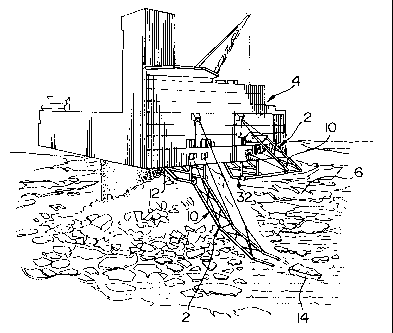
FIGURE 1 is a perspective view of the access and evacuation apparatus of the
present invention in place on an offshore work platform.
FIGURE 2 is a side elevation view of the apparatus of the present invention.
FIGURE 3 is a partial side elevation view of the apparatus in accordance with
an
embodiment of the present invention.
FIGURE 4 is a partial front view of the apparatus in accordance with an
embodiment of the present invention.
FIGURE 5 is a front elevation view of the support means of the apparatus in
accordance with an embodiment of the present invention.
FIGURE 6 is a side elevation view of the pick-up means of the apparatus in
accordance with an embodiment of the present invention.
FIGURES 7a to 7d are perspective views of the apparatus of the present
invention
shown in varying stages of deployment.
FIGURES 8a and 8b are side views of an alternate embodiment of the access and
evacuation apparatus of the present invention.
While the invention will be described in conjunction with illustrated
embodiments, it will be understood that it is not intended to limit the
invention to such
embodiments. On the contrary, it is intended to cover all alternatives,
modifications and
CA 02279140 1999-07-29
-7-
equivalents as may be included within the spirit and scope of the invention as
defined by the
appended claims.
DETAILED DESCRIPTION OF THE PREFERRED EMBODIMENTS
In the following description, similar features in the drawings have been given
similar reference numerals.
Turning to the drawings, Figure 1 illustrates an offshore platform 4 having
two
access and evacuation apparatus 2, shown to be located within a significant
amount of ice
rubble 6. The apparatus 2 comprises an articulated arm 10 rotatably mounted on
the platform
4, for example on the underside 12 of the platform 4, as shown. A craft 14
used to transport
personnel on and off the platform 4 and a winch 16 for controlling the arm 10
may also be
provided.
With reference to Figure 2, the arm 10 comprises an inner part 20, which has a
first end 22 and a second end 24, and an outer part 26, which has a first end
28 and a second
end 30. The first end 22 is rotatably fixed to a framework 32(or the deck) in
turn fixed to
underside 12 of the platform 4. Inner part 20 may thus rotate about the pivot
axis 34. The
axis 34 is typically a distance d of about five (5) meters below the underside
12 of the
platform 4. The amount of rotation of the inner part 20 of the arm 10 can be
controlled by a
restraining means, shown in the drawings as cable 38 typically attached to an
outside face 40
of the platform 4 and to the second end 24 of inner part 20. A mechanical stop
or braking
mechanism may also be employed to limit the range of rotation of the inner
part 20. The
CA 02279140 1999-07-29
-8-
typical angle of rotation a of the inner part 20 will vary with the length of
the inner part 20.
For a length of approximately 15 meters, the angle of rotation a is preferably
in the range of
30 to 40 .
The inner part 20 and outer part 26 of the arm 10 are pinned together at 42 so
that
the outer part 26 may rotate relative to the inner part 20. Again, the
relative angle P between
the outer 26 and inner 20 parts will vary with the respective lengths of the
parts. As well, the
distance d below the platform 4 at which the first end 22 of the inner part 20
is fixed to the
structure 12wil1 affect the angle P. For a distance d of 5 meters, and parts
20 and 26 of equal
length of approximately 15 meters, angle (3 will preferably be initially
approximately 45
degrees. The arm 10 is preferably constructed such that both parts 20 and 26
comprise
spaced parallel members suitably braced. In any event, the second end 30 of
outer part 26
comprises a pair of members 53 between which the craft 14 may be supported.
With reference to Figures 3- 6 a novel carrying arrangement 43 for supporting
the
craft 14 on the arm 10 and deploying the craft 14 in the water, has also been
developed to
account for the rotation of the arm 10 and particularly the outer part 26. It
is of course very
important to maintain the trim of the craft 14 as level as possible while
moving between an
upper position 44 in which the second end 30 of the outer part 26 is adjacent
the platform 4
and a lower position 46 in which the second end 30 is at or below the surface
of the water and
remote from the platform 4.
The novel arrangement consists of a pick-up means 49 mounted on members 53
at the second end 30 of outer part 26 and support or bracket means 52 mounted
to the craft
CA 02279140 1999-07-29
-9-
14 for mating with the pick-up means 49. The pick-up means 49 comprises a
spaced pair of
coaxial pins 50 extending inwardly between members 53.
The support means 52 preferably comprises a pair of brackets 58, one mounted
on a respective support 59 to each side 60 and 62 of the craft 14 and having
an internal radius
r to receive the cylindrical members 50 so that the craft 14 and the brackets
58 are free to
rotate about members 50.
In use, the winch 16 will be placed on the platform 4 in an area 64 protected
from
extreme wind chill factors and ice accretion. The craft 14 may be stored close
to the platform
4 with the arm in the upper position 44 so that personnel may be quickly
evacuated from the
platform 4 in the case of fire or other emergency. The movement of the arm 10
is controlled
by the winch 16 and the cable 66 operatively connecting the winch 16 to the
outer part 26 of
the arm 10, adjacent to the members 53, to pay out at a controlled rate.
During deployment of the arm 10, as shown in the series of drawings in Figures
7a to 7d, the inner part 20 will begin to rotate about the pivot point 34
through the maximum
pre-determined range of motion, and the outer part 26 is required to rotate
with it. That is, the
angle (3 is mechanically fixed as the minimum angle between parts 20 and 26
during this first
phase of a launch. Once the inner part 20 has rotated its full amount, its
rotational movement
is stopped by the cable 38. The angle (3 between the inner part 20 and the
outer part 26 is
chosen such that when the rotation of the inner part 20 has stopped, the
second end 30 of the
outer part 26 has passed through a vertical line through the second end 24of
the inner part.
In common parlance, the center of gravity of the craft 14 will have passed
"top dead centre".
CA 02279140 1999-07-29
-10-
The outer part 26 then rotates about the pivot connection 42 from the
intermediate
position shown until the craft 14 reaches the water as shown in Figure 7d.
When the craft 14
reaches the water, further rotation of the part 20 allows the craft 14 to
float off of the pins 50
and move away from the arm 10. The outer part 26 continues to rotate through
to the lower
position 46 below the surface of the water remote from the platform 4 and away
from the craft
14 to prevent further interaction with the craft 14.
In all, the outer part 26 will typically preferably rotate through an angle of
up to
about 200 relative to the inner part 20, although other angles of rotation
will be acceptable.
The invention also contemplates use in partial or complete ice conditions. In
that
situation outer part 26 may not be able to rotate below water level and away
from the craft 14.
Nonetheless, there will be sufficient rotation to release the craft 14 even if
the craft 14 is on
top of the ice.
The speed at which the craft 14 is lowered may/can vary for different
environmental conditions into which the craft 14 is being deployed. In severe
sea conditions
the winch 16 can control the speed of the craft 14 to be at a vertical
velocity of approximately
2.5 meters per second. When extreme ice cover is present, the winch 16 is
designed to allow
deployment at a rapid rate during the first segment of the launch, but to
automatically reduce
the vertical velocity during the second, final, segment. This places the craft
14 gently on the
ice without causing structural damage to the craft 14 itself, or injury to the
personnel being
transported within the craft 14.
Two general embodiments are specifically contemplated in the design of the
apparatus 2. In the first, the inner part 20 would take about 15 seconds to
rotate from the
CA 02279140 1999-07-29
-11-
upper position 44 to the intermediate position shown in Figure 7b. The
rotation of the outer
part 26 would automatically speed up increasing the vertical velocity of the
craft 14 to
approximately 2.5 meters per second. Total launch time, from the upper
position 44 to the
lower position 46 would be preferably about 35 seconds.
The second embodiment is contemplated for launch onto an ice field with up to
complete ice cover. The inner part 20 would rotate at the same speed as the
first embodiment.
However, the winch 16 would then slow the pay-out rate of the cable 64, thus
slowing the
rotation of the outer part 26 and hence the vertical velocity of the craft 14.
The total
deployment time will be preferably about 1.25 minutes.
In either embodiment, the craft 14 will be deployed and the arm 10 will
continue
to rotate into the water sufficiently to release craft 14.
In an alternate embodiment of the present invention as illustrated in Figures
8a
and 8b, the apparatus 102 is pinned to the platform 104 in a manner such that
it is free to
rotate about the pivot axis 106. The apparatus 102 comprises an arm 108 having
an inner part
110 which has a first end 112 and a second end 114, and an outer part 116
which has a first
end 118 and a second end 120. The second end 114 of the inner part 110 is
rotationally
connected to the first end 118 of the outer part 116. There is also provided a
winch 124 on
the platform 104 with a winch cable 126 attached to the inner part 110 at a
point below the
second end 114. The inner part 110 is held in place prior to operation by a
brake on the winch
124. Releasably held at second end 120 there is shown a craft 128 used to
transport personnel
on and off the platform 104.
CA 02279140 1999-07-29
-12-
A mechanical connection is provided between inner part 110 and outer part 116
to increase angle y between the two parts responsive to the lowering of inner
part I 10 by cable
126.
In one preferred mode for effecting this mechanical connection, a cable 130,
or
series of cables, are positioned parallel to the inner part 110, as shown. At
one end 132
thereof, the cable 130 is wrapped around a first drum 134, the drum 134 being
fixed at the
first end 112 to the deck, preferably in a clockwise direction. The other end
136 of the cable
130 is wrapped around a second drum 138 fixed to the first end 118 of the
outer part 116 by
a weld or the like. The second drum 13 8 is thus not free to independently
rotate about its axis.
Rather, when the second drum 138 rotates to take up or release the cable 130,
the outer part
116 rotates with it.
In operation, the winch brake 124 is released such that the apparatus 102 is
free
to move. The winch wire 126 pays out as gravity forces the arm 108, with the
craft 128
attached, downwardly. As the inner part 110 rotates, the cable130 is taken up
around the first
drum 134 The resulting tension in the cable 130 pulls against the second drum
138 causing
it to rotate in a counterclockwise direction. That counterclockwise rotation
is translated to
outer part 116 (as described above) as a downward tension in order to pivot
outer part 116
upwardly and outwardly against the gravitational pull acting on the arm 108
relative to the
rotation of the inner part 110 (as shown in phantom in Figure 8a). Thus, as
shown in Figure
8b, the craft 128 may be placed in the water or on the ice remote from the
platform 104 in a
manner similar to the first embodiment described herein, at which point the
arm 108 continues
to rotate into the water (as shown in phantom in Figure 8b).
CA 02279140 1999-07-29
- 13 -
Thus, it is apparent that there has been provided in accordance with the
invention
an access and evacuation apparatus for an offshore platform that fully
satisfies the objects,
aims and advantages set forth above. While the invention has been described in
conjunction
with illustrated embodiments thereof, it is evident that many alternatives,
modifications and
variations will be apparent to those skilled in the art in light of the
foregoing description.
Accordingly, it is intended to embrace all such alternatives, modifications
and variations as
fall within the spirit and broad scope of the invention.