Language selection

Search

Patent 2279558 Summary

Third-party information liability

Some of the information on this Web page has been provided by external sources. The Government of Canada is not responsible for the accuracy, reliability or currency of the information supplied by external sources. Users wishing to rely upon this information should consult directly with the source of the information. Content provided by external sources is not subject to official languages, privacy and accessibility requirements.

Claims and Abstract availability

Any discrepancies in the text and image of the Claims and Abstract are due to differing posting times. Text of the Claims and Abstract are posted:

  • At the time the application is open to public inspection;
  • At the time of issue of the patent (grant).
(12) Patent: (11) CA 2279558
(54) English Title: SEALING ARRANGEMENT WITH AUTOMATIC CLEARANCE ADJUSTMENT
(54) French Title: DISPOSITIF ETANCHE AYANT UN SYSTEME DE REGLAGE D'ECARTEMENT AUTOMATIQUE
Status: Expired
Bibliographic Data
(51) International Patent Classification (IPC):
  • F02C 7/28 (2006.01)
  • F16J 15/34 (2006.01)
  • F16J 15/44 (2006.01)
(72) Inventors :
  • BAINACHI, DANIEL OLIVIER (France)
(73) Owners :
  • SNECMA (France)
(71) Applicants :
  • SOCIETE NATIONALE D'ETUDE ET DE CONSTRUCTION DE MOTEURS D'AVIATION "SNECMA" (France)
(74) Agent: LAVERY, DE BILLY, LLP
(74) Associate agent:
(45) Issued: 2008-12-09
(22) Filed Date: 1999-08-03
(41) Open to Public Inspection: 2000-02-05
Examination requested: 2004-05-19
Availability of licence: N/A
(25) Language of filing: English

Patent Cooperation Treaty (PCT): No

(30) Application Priority Data:
Application No. Country/Territory Date
98 10041 France 1998-08-05

Abstracts

English Abstract

The seal is composed of butt-jointed segments (1) in which the bearing surface (18) on a rotating part (2) subject to wear, includes a hollow chamber (20) communicating through calibrated orifices (22) with a high pressure containment (8). Therefore, it fills up with gas which tends to force it away from the surface, thus reducing the contact pressure without introducing excessive leaks. Figure 2.


French Abstract

Le joint est composé de segments (1) mis bout à bout, dans lesquels la surface d'appui (18) sur une pièce rotative (2) sujette à l'usure comprend une chambre creuse (20) communiquant à travers des orifices calibrés (22) avec un confinement haute pression (8). Par conséquent, il se remplit de gaz qui tend à l'écarter de force de la surface, réduisant ainsi la pression de contact sans présenter de fuites excessives. Figure 2.

Claims

Note: Claims are shown in the official language in which they were submitted.


7

CLAIMS


1. A sealing apparatus, comprising:
a plurality of butt jointed segments positioned between
a high pressure containment and a low pressure containment,
the plurality of butt jointed segments each having a sealing
face, a first face portion subject to a high pressure in the
high pressure containment and a second face portion subject
to a low pressure in the low pressure containment, the first
and second face portions being positioned on an opposite side
of the sealing face;
a surrounding spring configured to join the plurality of
butt jointed segments together and urge the plurality of butt
jointed segments to maintain a frictional contact with an
element extending through the high pressure containment and
the low pressure containment; and
a thrust lip provided on the sealing face and configured
to form a chamber with the element when the thrust lip is in
contact with the element;
wherein the plurality of butt jointed segments each has
a plurality of orifices communicating the chamber and the
high pressure containment and configured to produce pressure
loss in the chamber such that the chamber has a lower
pressure than the high pressure containment; and
wherein the plurality of orifices is calibrated to a
diameter which does not allow the high pressure in the high
pressure containment to fill the chamber.

2. The sealing apparatus according to claim 1, wherein
the plurality of butt jointed segments is configured to
permit a specific clearance element to allow permeability to
air.


8

3. The sealing apparatus according to claim 1, wherein
the sealing face comprises a plurality of thrust pads
provided inside the thrust lip and configured to press
against the element.


4. The sealing apparatus according to claim 1, wherein
the plurality of butt jointed segments each has an arc shape
and forms a circle around the element.


5. A sealing apparatus, comprising:
a plurality of segments positioned between a high
pressure containment and a low pressure containment, said
plurality of segments each having a sealing face, a first
face portion subject to a high pressure in the high pressure
containment and a second face portion subject to a low
pressure in the low pressure containment, said first and
second face portions being positioned on an opposite side of
said sealing face;
a spring configured to join said plurality of segments
around a rotatable shaft extending through the high and low
pressure containments and configured to urge said plurality
of segments against the rotatable shaft; and
a thrust lip provided on said sealing face and
configured to form a chamber with the rotatable shaft when
said thrust lip is in contact with the rotatable shaft;
wherein said plurality of segments each has at least one
orifice communicating the chamber and the high pressure
containment and configured to produce pressure loss in the
chamber such that the chamber has a lower pressure than the
high pressure containment; and
wherein said at least one orifice is calibrated to a
diameter which does not allow the high pressure in the high
pressure containment to fill the chamber.


9

6. The sealing apparatus according to claim 5, wherein
said plurality of segments is configured to permit a
clearance for permeability to air.


7. The sealing apparatus according to claim 5, wherein
said plurality of segments each comprises at least one thrust
pad positioned inside the thrust lip and configured to press
against the rotatable shaft.


8. The sealing apparatus according to claim 5, wherein
said plurality of segments each has an arc shape and forms a
circle around the rotatable shaft.


9. The sealing apparatus according to any one of
claims 1 to 8, wherein different pressures exist in different
internal volumes.

Description

Note: Descriptions are shown in the official language in which they were submitted.


CA 02279558 1999-08-03
1

DESCRIPTION
SEALING ARRANGEMENT WITH AUTOMATIC CLEARANCE ADJUSTMENT
The invention relates to a sealing arrangement,
particularly including a seal with automatic clearance
adj ustment .
This seal forms part of the family of segmented
seals composed of elements called segments that are
butt-jointed and each extend over a portion of the
circumference; these segments are connected together
by a surrounding spring that tends to force them into
contact with a part such as a shaft with which the seal
is to be formed.
The problem that arises in this case is wear of the
seal caused by friction due to the shaft rotating on
the seal; since this wear is proportional to the shaft
rotation speed and the pressure of the segments, it is
desirable to minimize this pressure. One method would
be to suitably choose the spring or to adjust its
characteristics, particularly making sure that it is
not too tight, but in reality this would not be very
easy or even very useful since this force is very small
compared with the radial pressure force exerted on the
segments. Another solution is to use the rotation
speed of the rotor to create a hydro-dynamic air
pressure at the contact between segments and the rotor,
subject to some arrangements on segments (Rayleigh
pads). The major disadvantage of this technology is
that it is inefficient at low and medium rotor speeds.
Therefore, up to now there has been no efficient way of
limiting wear of segmented seals, which explains why
SP 15008 JCI


CA 02279558 1999-08-03
2

they only last for a few thousand hours which is quite
inadequate for most applications.
The arrangement proposed in this description is
characterized by an automatic reduction in the pressure
at which seal segments are forced into contact with the
friction part, and possibly elimination of this
pressure. In its most general form, the sealing
arrangement described in this description comprises a
seal composed of butt jointed segments in the shape of
an arc of a circle and a surrounding spring joining the
segments together, the segments having a sealing face
on the side opposite the spring and being laid out in
contact with a part passing through an opening in a
wall separating a high pressure containment from a low
pressure containment; this arrangement is
characterized in that the seal is put into position in
front of the opening with high pressure applied to a
first portion of one face opposite the sealing face and
low pressure applied to a second portion of the said
face opposite the sealing face, and in that the sealing
faces are shaped to form a chamber surrounded by a
thrust lip acting on the part, orifices passing through
the segments from the chambers as far as the high
pressure containment. As will be seen, the orifices
(which may be calibrated to a given diameter, for
example 1 millimeter) enable a pressure to be set up in
the chambers to reduce the tightness of the segments.
Preferably, the seal is made and laid out such that the
forces due to the radial pressure, the spring, and due
to friction on segments generate a minimum contact
pressure between the segments and the friction part, or
cancel out for a specific clearance between segments
and the friction part, guaranteeing the required
SP 15008 JCI


CA 02279558 1999-08-03
3

permeability to air. There is a clear distinction
between this type of seal and seals such as those
described in French patent 2 688 283 which move axially
in front of an opening to produce two sealing states
depending on the pressure difference and which are not
segmented, and also seals described in French patent 2
613 019 in which a liquid is injected through the seal
to separate the segments from the shaft. The latter
seal requires a special high pressure supply circuit in
order to inject the liquid and to retrieve it.
One illustrative embodiment of the invention will
now be described in more detail with reference to the
following figures:

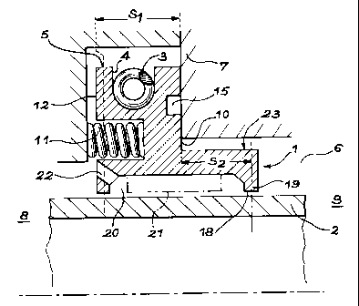
= figure 1 is a general view of the seal,

= figure 2 is a sectional view of a segment of the
seal,

= figure 3 is a cross-sectional view of the static
sealing face of a segment,

= and figure 4 is a view of the dynamic sealing
face of a segment.
Firstly, note with reference to figure 1 that a
segmented seal is composed of a number of butt-jointed
segments, four in this case, each extending around a
quarter of the circumference, and pressed into contact
with the surface of a shaft 2 by a surrounding spring 3
that surrounds them and holds them together. With
reference to figure 2, it can be seen that the spring 3
is held in a groove 4 in the radially external face 5
of segments 1. Shaft 2 passes through an opening 6 in
a stator 7 that delimits a first containment 8 and a
second containment 9 between which the separation must
be maintained despite the opening 6. Therefore, the
seal provides a dynamic seal with shaft 2 since the
SP 15008 JCI


CA 02279558 1999-08-03
4

shaft turns, and a static seal with the stator 7 with
which the segments 1 are kept in contact through their
rear face 10, which can be seen better in figure 3.
Axial springs 11, compressed between the stator 7 and
the forward face 12 of segments 1, maintain this static
seal which is exerted by a lip 13 that is formed over
part of the width of the rear face 10. Thrust pads 14,
the purpose of which is to limit the contact pressure,
are also pressed into contact with stator 7; they are
separated from lip 13 by a discharge groove 15. Figure
3 also shows that one of the ends of segments 1 forms a
recess 16 into which the opposite end 17 of the
adjacent segment 1 penetrates. This thus improves
cohesion of the seal, and particularly provides total
overlap of the opening 6 around the circumference.
Elements specific to the invention are located on
the radially internal part of segments 1 close to shaft
2; the sealing face 18 of each segment 1 is shaped to
present a peripheral lip 19 bearing on shaft 2, in
which a chamber 20 extends corresponding to a recess in
the surface 18; however, the chamber 20 is partially
occupied by thrust pads 21 also designed to exert
pressure on shaft 2 in order to reduce the contact
pressure exerted on lip 19. Calibrated orifices 22
penetrate segments 1 from chamber 20 as far as the high
pressure containment 8. Note that this portion
radially on the inside of segments 1 comprises an
extension 23 that extends in opening 6 on the side of
the low pressure containment 9.
The invention described in this document is fitted
in a turbo-machine, in which there are different
pressures in the different internal volumes, due to
SP 15008 JCI


CA 02279558 1999-08-03

pipes leading to different parts of the compressors, as
is well known to an expert in the subject.
The purposes of the various pressures is to
confine liquids in low pressure containments
5 (particularly lubrication oil in bearing chambers; the
seals are then used to complete the seal), to encourage
air drafts towards some parts of the machine to be
ventilated or to adjust deformations of flexible
membranes.
When the machine is at rest, segments 1 are
pressed into contact with shaft 2 by force Fr from the
surrounding spring 3, since there is no pressure at
that time; however, this is not serious because shaft
2 is not moving. When the machine is rotating, a
pressure Pl is set up in the high pressure containment
6 and a lower pressure P2 is set up in the low pressure
containment 9. These pressures exert centripetal
forces P1.S1 and P2.S2, on segment 1 according to the
notations in the figure, where Sl and S2 are the
surface areas of the outside face on which the two
pressures are applied (S2 being the surface area of the
extension, mentioned above, of segment 1 in opening 6);
furthermore, chamber 20 is filled at a pressure P3
which is slightly less than the pressure Pl due to
pressure losses produced through the calibrated
orifices 22, but is greater than pressure P2; this
pressure exerts a force on segment 1 opposite to the
previous forces, with an intensity approximately equal
to P3.(S1+S2). Therefore, the total force due to the
pressure is equal to Fr+Pl.S1+P2.S2-P3.(Sl+S2). Since
P3 is significantly closer to Pl than to P2, this total
force is less than the force Fr exerted at rest, which
means that the contact pressure of the seal on the
SP 15008 JCI


CA 02279558 1999-08-03
6

shaft 2 is reduced. If the seal is judiciously
designed, particularly with a sufficiently low spring
force Fr, and if areas Si and S2 are well chosen and if
the pressures Pl and P2 are sufficiently different,
this resulting force may even become negative, in other
words segments 1 will separate from shaft 2 and in this
case they will no longer be subject to wear; this
situation is preferred. A balance then tends to be set
up, since leaks occur from the high pressure
containment 8 towards the low pressure containment 9
through chamber 20, and the pressure P3 reduces as the
clearance between segment 1 and shaft 2 increases; it
can theoretically reach an average pressure equal to
(Pl+P2)/2 if the clearance is sufficient, but the force
exerted on segments 1 would then tend towards the value
Fr+i/2(Pl-P2)(S1-S2), which is normally positive since
the areas Si and S2 may be similar in many
arrangements. Therefore, equilibrium is usually
achieved with a value of P3 intermediate between its
value if there is no clearance and the average of
pressures P1 and P2; this value of the pressure is
obtained with a slight clearance between segments 1 and
shaft 2, which has the advantage of eliminating
friction while reducing air leaks between one
containment 8 and the other containment 9. The
diameter of the calibrated orifices 22 may be about 1
millimeter to ensure satisfactory operation, the
pressure P3 being just sufficient to separate segments
1.

SP 15008 JCI

Representative Drawing
A single figure which represents the drawing illustrating the invention.
Administrative Status

For a clearer understanding of the status of the application/patent presented on this page, the site Disclaimer , as well as the definitions for Patent , Administrative Status , Maintenance Fee  and Payment History  should be consulted.

Administrative Status

Title Date
Forecasted Issue Date 2008-12-09
(22) Filed 1999-08-03
(41) Open to Public Inspection 2000-02-05
Examination Requested 2004-05-19
(45) Issued 2008-12-09
Expired 2019-08-06

Abandonment History

There is no abandonment history.

Payment History

Fee Type Anniversary Year Due Date Amount Paid Paid Date
Application Fee $300.00 1999-08-03
Registration of a document - section 124 $100.00 1999-10-08
Maintenance Fee - Application - New Act 2 2001-08-03 $100.00 2001-07-18
Maintenance Fee - Application - New Act 3 2002-08-05 $100.00 2002-07-31
Maintenance Fee - Application - New Act 4 2003-08-04 $100.00 2003-07-28
Registration of a document - section 124 $50.00 2003-09-16
Request for Examination $800.00 2004-05-19
Maintenance Fee - Application - New Act 5 2004-08-03 $200.00 2004-07-21
Maintenance Fee - Application - New Act 6 2005-08-03 $200.00 2005-07-28
Maintenance Fee - Application - New Act 7 2006-08-03 $200.00 2006-07-25
Maintenance Fee - Application - New Act 8 2007-08-03 $200.00 2007-07-25
Registration of a document - section 124 $100.00 2008-01-02
Maintenance Fee - Application - New Act 9 2008-08-04 $200.00 2008-07-24
Final Fee $300.00 2008-09-23
Maintenance Fee - Patent - New Act 10 2009-08-03 $250.00 2009-07-27
Maintenance Fee - Patent - New Act 11 2010-08-03 $250.00 2010-07-26
Maintenance Fee - Patent - New Act 12 2011-08-03 $250.00 2011-07-25
Maintenance Fee - Patent - New Act 13 2012-08-03 $250.00 2012-07-23
Maintenance Fee - Patent - New Act 14 2013-08-05 $250.00 2013-07-24
Maintenance Fee - Patent - New Act 15 2014-08-04 $450.00 2014-07-24
Maintenance Fee - Patent - New Act 16 2015-08-03 $450.00 2015-07-24
Maintenance Fee - Patent - New Act 17 2016-08-03 $450.00 2016-07-20
Maintenance Fee - Patent - New Act 18 2017-08-03 $450.00 2017-07-20
Maintenance Fee - Patent - New Act 19 2018-08-03 $450.00 2018-07-19
Owners on Record

Note: Records showing the ownership history in alphabetical order.

Current Owners on Record
SNECMA
Past Owners on Record
BAINACHI, DANIEL OLIVIER
LEXVALL
SNECMA MOTEURS
SOCIETE NATIONALE D'ETUDE ET DE CONSTRUCTION DE MOTEURS D'AVIATION "SNECMA"
Past Owners that do not appear in the "Owners on Record" listing will appear in other documentation within the application.
Documents

To view selected files, please enter reCAPTCHA code :


To view images, click a link in the Document Description column. To download the documents, select one or more checkboxes in the first column and then click the "Download Selected in PDF format (Zip Archive)" or the "Download Selected as Single PDF" button.

List of published and non-published patent-specific documents on the CPD .

If you have any difficulty accessing content, you can call the Client Service Centre at 1-866-997-1936 or send them an e-mail at CIPO Client Service Centre.


Document
Description 
Date
(yyyy-mm-dd) 
Number of pages   Size of Image (KB) 
Claims 1999-08-03 1 42
Representative Drawing 2000-01-13 1 11
Claims 2008-01-29 3 98
Drawings 1999-08-03 2 48
Cover Page 2000-01-13 1 34
Abstract 1999-08-03 1 15
Description 1999-08-03 6 259
Claims 2006-10-03 2 87
Representative Drawing 2008-11-20 1 13
Cover Page 2008-11-20 1 38
Correspondence 2008-09-23 1 31
Prosecution-Amendment 2004-09-13 1 30
Correspondence 1999-09-08 1 2
Assignment 1999-08-03 3 94
Assignment 1999-10-08 2 73
Fees 2003-07-28 1 36
Assignment 2003-09-16 51 2,439
Prosecution-Amendment 2008-01-29 5 148
Fees 2007-07-25 1 48
Fees 2002-07-31 1 47
Fees 2001-07-18 1 40
Prosecution-Amendment 2004-05-19 1 23
Fees 2004-07-21 1 38
Fees 2005-07-28 1 33
Prosecution-Amendment 2006-04-04 2 48
Fees 2006-07-25 1 44
Prosecution-Amendment 2006-10-03 4 148
Prosecution-Amendment 2007-07-30 2 38
Assignment 2008-01-02 10 666
Fees 2008-07-24 1 43