Language selection

Search

Patent 2279568 Summary

Third-party information liability

Some of the information on this Web page has been provided by external sources. The Government of Canada is not responsible for the accuracy, reliability or currency of the information supplied by external sources. Users wishing to rely upon this information should consult directly with the source of the information. Content provided by external sources is not subject to official languages, privacy and accessibility requirements.

Claims and Abstract availability

Any discrepancies in the text and image of the Claims and Abstract are due to differing posting times. Text of the Claims and Abstract are posted:

  • At the time the application is open to public inspection;
  • At the time of issue of the patent (grant).
(12) Patent Application: (11) CA 2279568
(54) English Title: INSTALLATION AND PROCESS FOR MEASURING THE UNROUNDNESS AND DIAMETER OF RAILWAY WHEELS
(54) French Title: BANC DE MESURE ET MESURE DU MANQUE D'ARRONDI ET DU DIAMETRE DES ROUES DE TRAINS
Status: Deemed Abandoned and Beyond the Period of Reinstatement - Pending Response to Notice of Disregarded Communication
Bibliographic Data
(51) International Patent Classification (IPC):
  • G01M 17/10 (2006.01)
  • B61K 9/12 (2006.01)
  • G01B 11/24 (2006.01)
(72) Inventors :
  • LOPEZ GOMEZ, JOSE LUIS (Spain)
  • SANCHEZ REVUELTA, ANGEL LUIS (Spain)
  • GOMEZ GOMEZ, CARLOS JAVIER (Spain)
(73) Owners :
  • PATENTES TALGO, S.A.
(71) Applicants :
  • PATENTES TALGO, S.A. (Spain)
(74) Agent: MCCARTHY TETRAULT LLP
(74) Associate agent:
(45) Issued:
(22) Filed Date: 1999-07-29
(41) Open to Public Inspection: 2000-02-12
Examination requested: 2001-07-26
Availability of licence: N/A
Dedicated to the Public: N/A
(25) Language of filing: English

Patent Cooperation Treaty (PCT): No

(30) Application Priority Data:
Application No. Country/Territory Date
P9801744 (Spain) 1998-08-12

Abstracts

English Abstract


Installation and process for measuring the unsoundness and
diameter of railway wheels using a rolling rail (2) along which
the railway wheel (1) to be measured passes, and a guard-rail
(8) to center said wheel during the measurement process.
Several compact light sources (3) project compact light beams
(9) over the wheel (1), such that they continuously interfere
with the wheel flange and rolling band, the images produced by
said compact light beams being projected over an opaque filter
(4). A video camera (5) captures the images projected over the
opaque filter (4) and sends them to a computer (6), where said
images are filed to process them later on. The measurement
process is initiated by a trigger system (7) which detects the
presence of a wheel (1) and activates or deactivates the
measuring equipment. The invention is applicable to the repair
and maintenance of railway wheels.


Claims

Note: Claims are shown in the official language in which they were submitted.

6
C L A I M S
1.- An installation for measuring the unroundness and
diameter of railway wheels using artificial vision,
characterized in that it comprises for each side of a railway
line: a rolling rail (2) over which the railway wheel (1)
passes, to be measured at a speed of 5 to 10 Km/h; a guard-rail
(8) to center said wheel (1) during the measurement process;
several compact light sources (3) to project compact light beams
(9) over the wheel (1), such that they continuously interfere
with the flange and rolling band of the wheel; an opaque filter
(4) over which the images produced by said compact light beam
(9) are projected; a video camera (5) to capture the images
projected over the opaque filter (4); a computer (6) connected
to the video camera (5) and destined to file the images captured
by the latter and process them later on; and a trigger system
(7) to detect the presence of a wheel (1) and to activate or
deactivate the measuring equipment.
2.- An installation according to claim 1, characterized in
that the video camera (5) is designed to obtain and store
between 50 and 76 images per second.
3.- An installation according to claims 1 and 2,
characterized in that the measurement length (L) is equal or
less than that of the bogie wheelbase, preferably 200 mm less
than said wheelbase.
4.- An installation according to claims 1 to 3,
characterized in that it comprises four compact light sources
(3).
5.- An installation according to claims 1 to 4,
characterized in that said compact light sources (3) are
cylindrical lasers.

7
6.- A process for measuring the unroundness and diameter of
railway wheels in which the installation of claims 1 to 5 is
used, characterized in that the measurement equipment is
activated with the trigger system (7); several compact light
beams (9) are projected, preferably four beams, from the compact
light sources (3) over the wheel (1) to be measured, such that
said beams continuously interfere with the wheel flange and
rolling band; the images generated by the compact light beams
(9) are projected over the opaque filter (4); the images
projected over the opaque filter (4) are captured with the video
camera (5), filing the images in said camera; and the video
camera (5) images are fed to a computer (6), where they are
filed for later processing.

Description

Note: Descriptions are shown in the official language in which they were submitted.


CA 02279568 1999-07-29
1
INSTALLATION AND PROCESS FOR MEASURING THE UNROUNDNESS AND
DIAMETER OF RAILWAY WHEELS
FIELD OF THE INVENTION
The present invention refers to the measurement of the
unroundness of wheels as the difference between the maximum and
minimum height of the flange, being based on the fact that the
flange circumference does not go out of roundness, such that
when the rolling band does so, variations in flange height are
produced along the wheel development. In this measurement,
artificial vision is used.
The mean flange height is taken as the mean and true height
value.
If the diameter value of the last rolling band lathing is
taken, twice the flange height of the last lathing is added and
twice the height obtained as a mean value of this equipment is
subtracted, the current diameter of the rolling band is
obtained.
With a suitable computerized support it is possible to
determine the "rolling diameter ovalization and mean diameter
value" parameters.
BACKGROUND OF THE INVENTION
The prior art to measure the unroundness and diameter of
railway wheels is based on mechanical contacts, a background of
measurement by artificial vision being unknown. Nevertheless,
artificial vision has been used to measure different rolling
parameters in railway vehicle wheels, being possible to mention
document EP-A-0 751 371 of the present applicant as an example.

CA 02279568 1999-07-29
2
SUN~IARY OF THE INVENTION
For a train moving on a track at a speed comprised between
5 and 10 Km/h, the invention basically consists in the
projection of several beams of compact light, for example, four,
over the wheel to be measured, such that the former continuously
interfere with the flange and the rolling band of the wheel. The
compact light sources may consist of cylindrical lasers.
The images generated by the compact light beams are
captured through an opaque filter by a video camera, which files
the images obtained at a rate of 50 to 76 images per second.
These images are sent to a computer, where they are filed for
later processing.
The length of the measurement installation will be equal or
less than the bogie wheelbase which has been provided with a
minimum value of 1.8 m. Preferably, the installation length will
be 200 mm shorter than the bogie wheelbase.
Under these conditions, the complete development of the
wheel will not be checked, such that it will be necessary to
double or triple the basic installation until managing to
measure the entire wheel development.
BRIEF DESCRIPTION OF THE DRAWINGS
The invention is described in greater detail below,
referring to the attached drawings, in which:
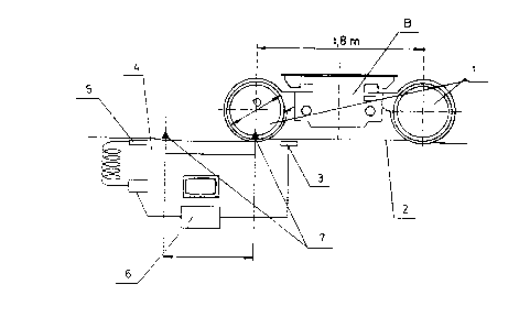
- Figure 1 shows the arrangement as a whole of the
installation of the invention and,
- Figure 2 shows the wheel rolling per rail, the
interference with the light beams and the parameters to be

CA 02279568 1999-07-29
measured.
3
DETAILED DESCRIPTION OF THE INVENTION
Firstly referring to Figure 1, a bogie B is observed with
wheels 1 to be measured which circulate along a rolling zone 2.
Compact light sources 3 project compact light beams which
interfere with the rolling during the distance L. This distance
is selected as equal or less than 1.8 m, or may be calculated in
accordance with the equation L = D/2 * n, wherein D is the wheel
diameter shown in Figure 1.
An opaque filter 4 permits images to be obtained like those
shown in Figure 2, and a camera objective 5 captures on a video
the images projected over the opaque filter 4, at a rate of 50
to 76 images/second.
The images captured by the video camera 5 are sent to a
computer 6, where they are filed for later processing.
The installation shown in Figure 1 is completed with a
trigger system 7, which detects the presence of a wheel 1 and
activates or deactivates the measuring equipment.
Referring now to Figure 2, a rail is observed in the
rolling zone 2, a wheel 1 to be measured leans on said rail and
a guard-rail 8 keeps the wheel centered during the measuring
process.
Likewise, observed in Figure 2 are the interference images
of the wheel with the compact light beams 9, captured by the
video camera 5. These interference images are filed in the
computer 6 indicated in Figure 1, and later the measurements K1,
K2, K3, and b are obtained, as well as al, az, a3, hence obtaining
the height measurements hl, h2 and h3, at several points of the
wheel development. All the measurements are illustrated in
Figure 2.

CA 02279568 1999-07-29
4
Between 50 and 76 value trios will be obtained for the
entire wheel development.
Comparing values hii, h2i and h3i, the ovalization of the
three rolling circles cl, cz and c3 will be obtained as the
difference between hi~.,~x and himin.
As resulting from Figure 2, the following equations are
satisfied:
h: = K1 + al - b
h2 = KZ + aZ - b
h3 = K3 + aj - b
The mean of the h2 values is the mean value of the height
and is expressed by the following ratio:
~hz
_ _____
hi
GO
Likewise the equation below is satisfied:
Dma = Dm + 2 h - 2 hm
wherein Dm is the diameter measured in the last machining,
h is the flange height measured in the last machining, D",a is the
current wheel diameter and hmis the current wheel flange height.
By using the installation of the invention, it will be
possible to measure rolling heights throughout the development
of a wheel by means of artificial vision, as well as obtaining
the rolling circle ovalization as the difference between hmaX and
hmimof the different circles along the development of the wheel.
Likewise, with the installation of the invention the
rolling diameter may be obtained starting from that obtained in
the last machining and considering the mean height of the

CA 02279568 1999-07-29
rolling circle which is located at 70 mm from the inside face of
the wheel.
5 Although the above gathers the essential features of the
present invention, it will be understood that the latter may be
varied or modified by the experts in the art . For this reason,
the scope of the invention is only limited by the contents of
the attached claims.

Representative Drawing
A single figure which represents the drawing illustrating the invention.
Administrative Status

2024-08-01:As part of the Next Generation Patents (NGP) transition, the Canadian Patents Database (CPD) now contains a more detailed Event History, which replicates the Event Log of our new back-office solution.

Please note that "Inactive:" events refers to events no longer in use in our new back-office solution.

For a clearer understanding of the status of the application/patent presented on this page, the site Disclaimer , as well as the definitions for Patent , Event History , Maintenance Fee  and Payment History  should be consulted.

Event History

Description Date
Inactive: IPC from MCD 2006-03-12
Application Not Reinstated by Deadline 2003-07-29
Time Limit for Reversal Expired 2003-07-29
Inactive: Agents merged 2003-02-05
Deemed Abandoned - Failure to Respond to Maintenance Fee Notice 2002-07-29
Amendment Received - Voluntary Amendment 2001-11-30
Letter Sent 2001-09-25
Request for Examination Requirements Determined Compliant 2001-07-26
Request for Examination Received 2001-07-26
All Requirements for Examination Determined Compliant 2001-07-26
Application Published (Open to Public Inspection) 2000-02-12
Inactive: Cover page published 2000-02-11
Inactive: First IPC assigned 1999-09-24
Application Received - Regular National 1999-09-08
Filing Requirements Determined Compliant 1999-09-08
Letter Sent 1999-09-08
Inactive: Filing certificate - No RFE (English) 1999-09-08

Abandonment History

Abandonment Date Reason Reinstatement Date
2002-07-29

Maintenance Fee

The last payment was received on 2001-07-19

Note : If the full payment has not been received on or before the date indicated, a further fee may be required which may be one of the following

  • the reinstatement fee;
  • the late payment fee; or
  • additional fee to reverse deemed expiry.

Please refer to the CIPO Patent Fees web page to see all current fee amounts.

Fee History

Fee Type Anniversary Year Due Date Paid Date
Application fee - standard 1999-07-29
Registration of a document 1999-07-29
MF (application, 2nd anniv.) - standard 02 2001-07-30 2001-07-19
Request for examination - standard 2001-07-26
Owners on Record

Note: Records showing the ownership history in alphabetical order.

Current Owners on Record
PATENTES TALGO, S.A.
Past Owners on Record
ANGEL LUIS SANCHEZ REVUELTA
CARLOS JAVIER GOMEZ GOMEZ
JOSE LUIS LOPEZ GOMEZ
Past Owners that do not appear in the "Owners on Record" listing will appear in other documentation within the application.
Documents

To view selected files, please enter reCAPTCHA code :


To view images, click a link in the Document Description column. To download the documents, select one or more checkboxes in the first column and then click the "Download Selected in PDF format (Zip Archive)" or the "Download Selected as Single PDF" button.

List of published and non-published patent-specific documents on the CPD .

If you have any difficulty accessing content, you can call the Client Service Centre at 1-866-997-1936 or send them an e-mail at CIPO Client Service Centre.


Document
Description 
Date
(yyyy-mm-dd) 
Number of pages   Size of Image (KB) 
Representative drawing 2000-01-28 1 8
Abstract 1999-07-29 1 25
Description 1999-07-29 5 156
Claims 1999-07-29 2 60
Drawings 1999-07-29 2 28
Cover Page 2000-01-28 1 42
Courtesy - Certificate of registration (related document(s)) 1999-09-08 1 140
Filing Certificate (English) 1999-09-08 1 175
Reminder of maintenance fee due 2001-04-02 1 111
Acknowledgement of Request for Examination 2001-09-25 1 194
Courtesy - Abandonment Letter (Maintenance Fee) 2002-08-26 1 182