Note: Descriptions are shown in the official language in which they were submitted.
CA 02279640 2003-10-07
GRINDING BODY FOR ON-LINE ROLL GRINDING
BACKGROUND OF THE INVENTION
1. Field of the Invention
The present invention relates to a grinding body
for an on-line roll grinding device which is mounted and
used on a rolling mill.
2. Description of the Related Art
When on-line roll grinding is performed, it is
common practice, as shown in Fig. 16, that a plurality of
on-line roll grinding devices 20 are placed to face a roll
21 to be ground, each of the on-line roll grinding devices
20 having a grinding body 22 capable of reciprocating in
an axial direction of the roll 21 and rotatable along the
axial direction, and the grinding body 22 is pressed against
a surface of the roll 21, which is rotating, to grind the
surface of the roll 21. A shaft center 20a of the grinding
device 20 is set at the same height as an axis 21a of the
roll 21, or at a height displaced upward or downward (an
offset height H) by a certain distance from the axis 21a.
The shaft center 20a of the grinding device 20 is also set
to be horizontally inclined at an angle of a (e.g., 0.5
°) from a line 20b perpendicular to the axis 21a of the roll
21. This angle of inclination, a, is called a grindstone
pressing angle.
1
CA 02279640 1999-08-04
Such grinding of the roll 21 with the grinding
device 20 is known to pose the following problems : The
offset height H and the grindstone pressing angle a
that have been set vary because of wear of the roll
21 by rolling, or owing to adjustment of a gap between
the upper and lower rolls 21 and 21. Thus, the
grindstone contacts the surface of the roll 21 unevenly,
forming a spiral mark and deteriorating the roll
surface. Eventually, the roll becomes unusable.
Furthermore, roughening of the surface of the roll 21,
and vibrations of the roll 21 due to an increased gap
between the roll surface and the grinding body 22,
cause the vibration of the grinding body 22, thereby
forming a pitching surface mark 23 with a streaked
pattern, as shown in Fig. 17, on the surface of the
roll 21 to be ground. Rotary grinding bodies for
preventing the formation of the pitching surface mark
23 or the spiral mark were proposed by ~l Japanese
Unexamined Patent Publication No. 6-47654
(hereinafter referred to as the earlier technology I) ,
2~ Japanese Unexamined Patent Publication No. 9-1463
(hereinafter referred to as the earlier technology II) ,
and ~3 Japanese Unexamined Utility Model Publication
No. 62-95867 (hereinafter referred to as the earlier
technology III).
The earlier technology I, as shown in Figs. 18
to 19, tries to prevent the formation of the pitching
2
CA 02279640 1999-08-04
surface mark 23 by securing a thin grindstone 32 onto
a flexible, thin, circular base plate 31 having a
central portion rotatably supported to constitute a
low-rigidity grinding body 22, and absorbing
vibrations of the roll 21, during grinding, by local
warpage of the thin, circular base plate 31 of the
grinding body 22 pressed against the roll 21. Fig. 20
shows a state in which only an outer edge of the
grindstone 32 contacts the roll 21, so that the thin,
circular base plate 31 warps, thus bringing the entire
width of the grindstone into contact with the roll 21.
Fig. 21 shows a state in which only an inner edge of
the grindstone 32 contacts the roll 21.
The earlier technology II focuses on the fact
that when the grinding body of the earlier technology
I contacts the roll 21 at a circumferential portion
of the thin grindstone 32, as shown in Fig. 21, only
the warpage of the thin circular base plate 31 is not
enough to resolve the uneven contact. In light of this
fact, the earlier technology II, as shown in Figs . 22
to 25, secures a cup-shaped grindstone 42 onto a
circular base plate 41 having an inward groove 43
defined by a circumferential portion of the circular
base plate 41 bent on a surface side, thereby
constituting a grinding body. Making use of the groove
43, the earlier technology II attempts to resolve the
contact of only the outer edge or the inner edge of
3
CA 02279640 1999-08-04
the cup-shaped grindstone 42 with the roll surface,
thereby preventing the formation of the spiral mark.
The earlier technology III, as shown in Figs.
26 to 27, tries to prevent the formation of the pitching
surface mark by fixing a cup-shaped grindstone 52
having a bottom plate to a circulax base plate 51 by
means of a nut 55, with the bottom plate being
sandwiched between rubber plates 53 and 54 (Fig. 26) ,
or fixing a bottom plate of a cup-shaped grindstone
52 to a circular base plate 51 by means of a nut 55,
with a rubber plate 53 being sandwiched therebetween
(Fig. 27), so that vibrations of the roll 21 will be
absorbed by the rubber plate 53 (54).
With the grinding body of the earlier technology
I, the pitching surface mark 23 has been assumed to
occur because of vibrations of the roll 21 during
on-line grinding. As a countermeasure, the circular
base plate has been thinned to impart low rigidity to
the grinding body. However, the thinning of an
abrasive grain layer and a support portion
(collectively called a grindstone) to impart low
rigidity because of emphasis on flexibility involves
the following problems:
(1) Vibrations occurring in the grinding
body 22 during grinding include resonance vibrations
associated with vibrations of the roll 21, and
self-excited vibrations associated with stick-slips
4
CA 02279640 1999-08-04
at the interface between the grindstone and the roll
21 in contact with each other. The self-excited
vibrations occur because of the low dynamic stiffness
of the support member for the grindstone, i.e., the
circular base plate. The self-excited vibrations
lead to the formation of the pitching surface mark 23.
(2) Since the support member for the
grindstone is a flexible, thin, circular base plate,
uneven contact of the grindstone with the roll is
liable to occur, under a high grinding force, according
to changes in roll setting. Thus, the oscillating
speed and the grinding force are restricted, so that
the grinding power declines.
(3) If the thickness of the abrasive grain
layer secured to the thin circular base plate differs,
the rigidity of the grindstone also varies. Fig. 13
is a graph showing the relationship between the
thickness of a grindstone and the rigidity of the
grindstone. As a one-dot chain line in the drawing
indicates, decreases in the grindstone thickness
result in rapid decreases in the grindstone rigidity.
Thus, the accuracy of grinding lowers according to
changes in the rigidity of the grindstone.
To retain the grindstone rigidity, the abrasive
grain layer can be thickened only up to a predetermined
thickness. Thus, the life of the grindstone shortens.
(4) When the grindstone supported on the
CA 02279640 1999-08-04
flexible thin circular base plate is pressed against
the roll with a predetermined pressing force, local
warpage occurs, and the stress of the grindstone at
the site of warpage increases. Thus, the pressing
force is limited to a level at which the imposed stress
is below the allowable grindstone.stress.
Consequently, the grinding power is restricted. Fig.
14 is a graph showing the relationship between the
grindstone pressing force and the grindstone stress.
As indicated by a one-dot chain line in the drawing,
the imposed stress exceeds the allowable grindstone
stress when the pressing force is about SO kgf or more.
(5) To reduce the weight of the rotary
movable portion, the abrasive grain layer needs to be
thinned. Since the thickness of the abrasive grain
layer is thus restricted, the life of the grindstone
becomes short.
With the earlier technology II, special
deformation of the grooved circular base plate 41 has
resolved uneven contact of the grindstone with the roll.
However, the pitching surface mark associated with
self-excited vibrations, the problem with the earlier
technology I, has not been resolved.
According to the earlier technology III, the
pitching surfacemarkhas considerably been diminished
because of the effect of the rubber plate. However,
its diminution has not been complete. The reason is
6
CA 02279640 1999-08-04
that the inserted rubber plates 53 and 54 are exposed
to the outside, so that the damping effect of rubber
has not been fully exhibited owing to the penetration
of foreign matter or the deterioration of rubber.
SUMMARY OF THE INVENTION
The present invention has been accomplished in
view of the above-described problems. It is an object
of the invention to provide a grinding body for on-line
roll grinding; which can effectively prevent the
formation of a spiral mark and a pitching surface mark,
which can improve the grinding power and grinding
accuracy, and which can prolong the life of a
grindstone.
To attain the above object, an aspect of the
present invention claims a grinding body for on-line
roll grinding, comprising a grindstone mounted in a
cup shape on a surface portion, and near a peripheral
edge, of a circular support base plate, wherein:
a peripheral edge portion of the circular
support base plate has on a surface side thereof a
two-layer structure including a flat ring-shaped
portion jutting toward an inner periphery so as to
define a transverse groove-like gap opening inward;
the grindstone is mounted on the flat ring-
shaped portion; and
7
CA 02279640 1999-08-04
a damping material is filled and mounted into
the transverse groove-like gap.
According to this aspect of the invention, the
uneven contact of the grindstone with the roll is
resolved during roll grinding, the formation of a
spiral -nark on the roll surface is resolved, the
oscillating speed of the grinding body can be increased,
the grinding force is not restricted, and the grinding
power can be improved. Vibration energy generated in
the grindstone is mostly absorbed to the damping
material filled into the groove, and transmitted to
the circular support base plate. As a result,
self-excited vibrations in the grinding body
associated with stick-slips at the interface between
the grindstone and the roll in contact with each other
are markedly reduced, and the formation of a pitching
surface mark on the roll surface due to the self-
excited vibrations is resolved.
Preferably, an opening of the transverse
groove-like gap filled and mounted with the damping
material is sealed with a waterproof joint filler.
This sealing can prevent the penetration of foreign
matter, and protect the damping material, thus
preventing the deterioration of the grinding body.
Another aspect of the invention is a grinding
body for on-line roll grinding, comprising a
grindstone mounted in a cup shape on a surface portion,
8
CA 02279640 1999-08-04
and near a peripheral edge, of a circular support base
plate, wherein:
a peripheral edge portion of the circular
support base plate has on a surface side thereof a
two-layer structure including a flat ring-shaped
portion jutting toward an inner periphery so as to
define a transverse groove-like gap opening inward;
a plate thickness, c, of the flat ring-shaped
portion as one of two layers of the two-layer structure,
and a plate thickness, b, of the other layer of the
two-layer structure,, with the transverse groove-like
gap being sandwiched between the two layers, is in a
relation, b < c;
the grindstone is mounted on the flat ring-
shaped portion with the plate thickness c; and
a damping material is filled and mounted into
the transverse groove-like gap. .
According to this aspect of the invention, the
flat ring-shaped portion with a large thickness
minimally deforms during roll grinding, and excessive
stress does not occur in the grindstone ( including its
mating surface) . Thus, an increase in the grindstone
pressing force can enhance the grinding power.
Furthermore, even if the thickness of the grindstone
varies, the rigidity of the grindstone minimally
changes, and the grinding accuracy can be retained.
In addition, the abrasive grain layer can be thickened
9
CA 02279640 1999-08-04
to prolong the life span of the grindstone until its
replacement.
Preferably, an opening of the transverse
groove-like gap filled and mounted with the damping
material is sealed with a waterproof joint filler.
This sealing can prevent the penetration of foreign
matter, and protect the damping material, thus
preventing the deterioration of the grinding body.
BRIEF DESCRIPTION OF THE DRAWINGS
The present invention will become more fully
understood from the detailed description given
hereinbelow and the accompanying drawings which are
given by way of illustration only, and thus are not
limitative of the present invention, and wherein:
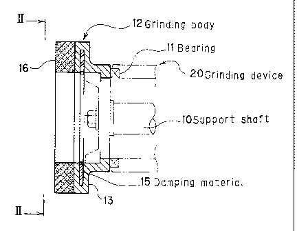
Fig. 1 is a vertical sectional side view of a
grinding body according to a first embodiment of the
present invention;
Fig. 2 is a view taken on line II-II of Fig. 1;
Fig. 3 is a partly enlarged view of Fig. 1;
Fig. 4 is a sectional view showing a state of
contact of only an outer portion of a cup-shaped
grindstone with a roll;
Fig. 5 is a sectional view showing a state of
contact of only an inner portion of a cup-shaped
grindstone with a roll;
CA 02279640 1999-08-04
Figs . 6 (a) and 6 (b) are graphs for comparing the
vibration waveform of a grindstone in the present
invention with that in the earlier technology;
Figs. 7 (a) and 7 (b) are graphs for comparing the
dynamic stiffness (compliance) of a grindstone in the
present invention with that in the earlier technology;
Figs. 8 (a) and 8 (b) are graphs for comparing the
status of a pitching surface mark in the present
invention with that in the earlier technology;
Fig. 9 is a vertical sectional side view of a
grinding body according to a second embodiment of the
present invention;
Fig. 10 is a partly enlarged view of Fig. 9;
Fig. 11 is an explanation drawing showing the
state of warpage of a circular support base plate of
the grinding body as the second embodiment of the
present invention;
Fig. 12 is an explanation drawing showing the
state of warpage of a circular support base plate of
a grinding body according to the earlier technology
I;
Fig. 13 is a graph showing the relationship
between the thickness and rigidity of a grindstone in
each of the present invention and the earlier
technology I;
Fig. 14 is a graph showing the relationship
between the pressing force and stress of a grindstone
11
CA 02279640 1999-08-04
in each of the present invention and the earlier
technology I;
Figs. 15(a) and 15(b) are graphs showing the
relationship between the pressing force of a
grindstone and grinding power in each of the present
invention and the earlier technology I;
Fig. 16 is a perspective view showing the
situation of on-line roll grinding;
Fig. 17 is a side view of a roll;
Fig. 18 is a side sectional view of a
conventional grinding body;
Fig. 19 is a front view of the conventional
grinding body;
Fig. 20 is a view showing an operating state of
the conventional grinding body;
Fig. 21 is a view showing a different operating
state of the conventional grinding body;
Fig. 22 is a side sectional view of a different
conventional grinding body;
Fig. 23 is a front view of the different
conventional grinding body;
Fig. 24 is a view showing an operating state of
the different conventional grinding body;
Fig. 25 is a view showing a different operating
state of the different conventional grinding body;
Fig. 26 is a sectional plan view of a further
different conventional grinding body; and
12
CA 02279640 1999-08-04
Fig. 27 is a sectional plan view of a modified
conventional grinding body.
PREFERRED EMBODIMENTS OF THE INVENTION
A grinding body for on-line_roll grinding
according to the present invention will now be
described in detail by way of the following Embodiments
with reference to the accompanying drawings, but it
should be understood that the invention is not
restricted thereby.
[First Embodiment]
In Figs. 1 to 3, the reference numeral 12 denotes
a grinding body having a central portion and a
peripheral edge portion rotatably supported by a
support shaft 10 and a bearing 11 of an on-line roll
grinding device 20. The grinding body 12 i~s composed
of a circular support base plate 13 of a metal, such
as SUS, constructed in a two-layer structure from a
horizontal jutting portion 13b and a flat ring-shaped
portion 13c, the horizontal jutting portion 13b
jutting outward from a short tubular portion 13a, and
the flat ring-shaped portion 13c extending upward and
then toward a central side from an outer peripheral
edge portion of the horizontal jutting portion 13b in
such a manner as to be opposed to the horizontal jutting
13
CA 02279640 1999-08-04
portion 13b while defining a transverse groove 14
opening toward the central side; a damping material
15 filled into the groove 14; and an integral,
cup-shaped grindstone 16 secured onto a surface of the
flat ring-shaped portion 13c. The reference numeral
17 denotes a joint filler, such as a waterproof
silicone material, provided to seal an opening of the
groove 14 when the damping material 15 is not
waterproof. As the damping material 15, a vibration
absorbing rubber member, such as a sand-containing one,
or a damper is used.
When only an outer end of the cup-shaped
grindstone 16 of the grinding body 12 contacts a
surface of a roll 21, and is pressed against it, as
shown in Fig. 4, the horizontal jutting portion 13b
below the groove 14 in the circular support base plate
13 warps outwardly downwardly. Thus, the entire width
of the cup-shaped grindstone 16 contacts the surface
of the roll 21. In this state, the grinding body 12
rotates.
When only an inner end of the cup-shaped
grindstone 16 of the grinding body 12 contacts the
surface of the roll 21, and is pressed against it, as
shown in Fig. 5, the flat ring-shaped portion 13c above
the groove 14 in the circular support base plate 13
warps inwardly downwardly. Thus, the entire width of
14
CA 02279640 1999-08-04
the cup-shaped grindstone 16 contacts the surface of
the roll 21. In this state, the grinding body 12
rotates.
Under these actions, the uneven contact of the
grindstone 16 with the surface of the roll 21 is
resolved. Thus, the formation of a_spiral mark on the
roll surface is resolved, the oscillating speed of the
grinding body can be increased, the grinding force is
not restricted, and the grinding power can be enhanced.
In this state, vibration energy occurring in the
cup-shaped grindstone 16 is mostly absorbed to the
damping material 15 filled into the groove 14, and
transmitted to the circular support base plate 13. As
a result, self-excited vibrations in the grinding body
12 associated with stick-slips at the interface
between the cut-shaped grindstone 16 and the roll 21
in contact with each other are markedly reduced, and
the formation of a pitching surface mark 23 on the
surface of the roll 21 due to the self-excited
vibrations is resolved.
Figs. 6(a) and 6(b) show the results of a
hammering test conducted to compare a vibration
waveform occurring in the grinding body (a) when the
damping material 15 is provided in the groove 14 as
in the present invention, and (b) when the damping
material 15 is absent as in the earlier technology II,
but with the same constitution provided. In these
CA 02279640 1999-08-04
drawings, the vertical axis represents the amplitude
relative to a reference line 0, while the horizontal
axis represents the passage of time in seconds . In the
absence of the damping material 15 (b), vibrations
under an external force continue at the same amplitude.
In the presence of the damping material 15 (a) , it is
clear that the amplitude is rapidly attenuated.
Figs. 7(a) and 7(b) show the results of a
hammering test conducted to compare displacement under
unit load (compliance) which occurs for each vibration
frequency, i.e., dynamic stiffness, in the circular
support base plate 13 (grinding body), (a) when the
damping material 15 is used, and (b) when the damping
material 15 is not used. In these drawings, the
vertical axis represents the vibration frequency in
Hz, while the horizontal axis represents the
displacement of the circular support base plate in
um/kgf at a major ratio (b) / (a) = 100/1 . In the absence
of the damping material 15 (b), displacement of about
230 um/kgf appears at maximum resonance. In the
presence of the damping material 15 (a) , displacement
at maximum resonance is about 1.6 um/kgf. Thus, the
dynamic stiffness of the circular support base plate
increases under the action of the damping material 15,
and the displacement of the circular support base plate
markedly decreases to about 1/100 of the value obtained
for (b). Thus, a damping effect can be obtained.
16
CA 02279640 1999-08-04
Furthermore, an opening of the groove 14 mounted
with the damping material 15 is sealed with the joint
filler 17. This sealing can prevent the penetration
of foreign matter, and protect the damping material
15, thus preventing the deterioration of the grinding
body.
Figs. 8 (a) and 8 (b) show the results of
investigation into the status of a pitching surface
mark under on-line grinding conditions (a) when the
damping material 15 is used, and (b) when the damping
material 15 is not used. In these drawings, the
horizontal axis represents the peripheral speed of the
roll (m/min), while the vertical axis represents the
grindstone pressing linear pressure (kgf/mm). In
experiments, on-line grinding operation was performed
for a constant period of time at roll peripheral speeds
of 600 m/min, 900 m/min, 1200 m/min and 1500 m/min under
a grindstone pressing linear pressure varied from 0.5
kgf/mm to 3 kgf/mm with a pitch of 0.5 kgf/mm. The
status of a pitching surface mark was evaluated
visually under the following criteria:
No pitching surface mark occurred =
"Satisfactory" O
A faint pitching surface mark occurred =
"Allowable" O
A clear pitching surface mark occurred =
"poor"
17
CA 02279640 1999-08-04
The results of Figs . 8 (a) and 8 (b) demonstrate
that the constitution of the present invention
combined with the damping material 15 resolves the
formation of a pitching surface mark which has occurred
with the earlier technologies.
[Second Embodiment]
Constitution
This embodiment is the preceding First
Embodiment, but with the constitution of the circular
support base plate 13 being partially changed such that
the plate thickness b of the horizontal jutting portion
13b and the plate thickness c of the flat ring-shaped
portion 13c will be in the relationship b < c. The same
members as in the First Embodiment are assigned the
same numerals, and their detailed explanations are
omitted.
In Figs. 9 to 10, dimensions for the plate
thickness in the circular support base plate 13 are
set such that the plate thickness c of the flat
ring-shaped portion 13c is greater than the plate
thickness b of the horizontal jutting portion 13b, i.e.,
b < c. Along with this configuration, the thickness
of the cup-shaped grindstone 16 can be made greater
than before, a . g. , can be increased to about 20 to 30
mm. Other constituent features of the grinding body
are nearly the same as in the First Embodiment, and
their explanations are omitted.
18
CA 02279640 1999-08-04
A ions and ffPrfi~
The surface of the grindstone 16 secured to the
flat ring-shaped portion 13c grinds the surface of the
roll 21 while rotating in contact with the roll 21.
During this grinding, the force, with which the
grindstone is pressed against the_roll, imposes a
warping, deforming force on the circular support base
plate 13. As stated above, the plate thickness b of
the horizontal jutting portion 13b and the plate
thickness c of the flat ring-shaped portion 13c are
set in the relation b < c. Thus, the flat ring-shaped
portion 13c given a great plate thickness minimally
deforms, while only the horizontal jutting portion 13b
with a small plate thickness warps and deforms.
Fig. 11 illustrates these situations found by
FEM analysis . When an external force is exerted on a
grinding surface of the grindstone 16 (its upper
surface in the drawing), the circular support base
plate 13 warps and deforms from a state indicated by
a solid line to a state indicated by a one-dot chain
line . As this deformation shows, deformation at a site
B is predominant, and there is no local deformation
at a site C. Thus; no overstress occurs in the
grindstone 16 (including its mating surface). With
the earlier technology I shown in Fig. 12, by contrast,
excessive stress may occur in the boundary line A
between the circular base plate 31 and the grindstone
19
CA 02279640 1999-08-04
32, damaging the grindstone 32.
Fig. 15 (a) shows the results of experiments for
measuring the grinding power per unit time versus the
grindstone pressing force for the present invention
(solid line) and the earlier technology I (one-dot
chain line). Fig. 15(b) is an enlarged view of Fig.
15 (a) for the earlier technology I (one-dot chain line) .
In these experiments, grinding was performed, using
a roll of nickel grains and a grindstone of CBN, at
a roll peripheral speed of 600 m/min and an oscillating
speed of a grinding device of 30 m/sec to 80 m/sec.
The amount of grinding per unit time was measured at
a plurality of points with different magnitudes of the
grindstone pressing force. In the case of the earlier
technology I indicated by the one-dot chain line in
the drawings, experiments were performed under the
same conditions, with the grindstone pressing force
restricted to a practical range of 40 kgf or less.
Similarly, the amount of grinding per unit time was
measured at a plurality of points with different
magnitudes of the grindstone pressing force.
According to the present invention, even when
the grindstone pressing force is rendered high as shown
by a solid line in Fig. 14, the stress of the grindstone
remains within the grindstone allowable stress
(indicated by a dashed line in the drawing) . Thus, the
grinding power can be enhanced by increasing the
CA 02279640 1999-08-04
grindstone pressing force, as indicated by the solid
line in Fig. 15(a). Furthermore, deformation at the
site B in Fig. 11 is predominant, and there is no local
deformation at the site C. As shown by the solid line
in Fig. 13, therefore, even when the thickness of the
grindstone varies, the rigidity of the grindstone
minimally changes. Consequently, the grinding
accuracy can be maintained. Besides, the absence of
location deformation at the site C makes it possible
to thicken the abrasive grain layer, thus prolonging
the life span of the grindstone 16 until replacement.
This invention being thus described, it will be
obvious that the same may be varied in many ways . Such
variations are not to be regarded as a departure from
the spirit and scope of the invention, and all such
modifications as would be obvious to one skilled in
the art are intended to be included within the scope
of the following claims.
21