Note: Descriptions are shown in the official language in which they were submitted.
CA 02279758 1999-07-30
STANF.115A PATENT
FAST, ENVIRONMENTALLY-STABLE FIBER SWITCHES
USING A SAGNAC INTERFEROMETER
Background of the Invention
Field of the Invention
The present invention is directed to a new architecture for an all-optical
fiber
or waveguide switch based on a fiber Sagnac interferometer.
Description of the Related Art
In an all-optical waveguide switch, a light signal is switched from one output
port to another by the application of either another optical signal of
different
wavelength (pump-induced switching) or by the light signal itself (self-
switching).
This is typically accomplished in an optical interferometer by placing an
element
possessing an optical third-order nonlinearity in one of the two arms of the
interferometer. For example, in the case of pump-induced switching, in the
absence
of pump light, the interferometer is adjusted (or fabricated) such that all
the signal
power comes out of one of the two output ports of the interferometer. When the
pump light is applied, it modifies the index of refraction of the nonlinear
element, and
thus the phase of the signal traveling in this arm. When the phase shift has
the right
value (which depends on the interferometer, but which is, as an example, 7t in
a
Mach-Zehnder interferometer), the signal is switched from one port to the
other.
Because third-order nonlinear effects are generally weak, they tend to require
relatively high intensities and/or long nonlinear media to produce this kind
of large
phase shift. The switching is then characterized by a high intensity-length
product.
Thus, an optical fiber which preserves a high optical intensity over very long
lengths
(kilometers) can produce a large phase shift at low optical powers. In fibers,
however,
only a few types of third-order nonlinearities are available. The most
commonly used
type is the Kerr effect. The Kerr effect is, however, notoriously weak in
silica fibers.
To make a Kerr-based switch in a silica fiber requires either a long fiber and
a
-1-
CA 02279758 1999-07-30
relatively low switching power, or a high power and a short fiber (or
waveguide). In
the former situation, the fiber arm needs to be so long that most
interferometers are
unstable and impractical. This is particularly true of the commonly-used
Mach-Zehnder interferometer, which needs to be in the sub-centimeter length
range
for its bias point to be stable over reasonable fiber temperature changes. In
the latter
situation, the fiber can be short and thus the interferometer can be more
stable, but the
power required to switch is too high. A high switching power is detrimental
because
it leads to breakdown of the fiber, because it is expensive, or both.
Other materials and other types of nonlinearity are much stronger than the
Kerr
effect in silica, and thus require smaller intensity-length products. One
particular
example is so-called resonantly enhanced nonlinearities, which occur in
materials
and/or dopants that possess suitable electronic transitions. Examples include
semiconductors, such as CdSeXS1-X, or GaAs, and chalcogenide glasses. (See,
M. Asobe, Low power all-optical switching in a nonlinear optical loop mirror
using
chalcogenide glass fibre, ELECTRONICS LETTERS, 18th July 1996, Vol. 32, No.
15, pp. 1396-1397.) A resonantly enhanced nonlinearity can also be observed in
dopants that can be introduced into a silica fiber, for example, a trivalent
rare earth
like erbium (Er3+) or neodymium (Nd3+). (See, M.J.F. Digonnet, et al.,
Resonantly
Enhanced Nonlinearity in Doped Fibers for Low-Power All-Optical Switching: A
Review, OPTICAL FIBER TECHNOLOGY, Vol. 3, 1997, pp. 44-64.) The advantage
of the latter type of nonlinearity is that one can still utilize a silica-
based fiber, i.e.,
retain all the basic low-loss, low-dispersion properties of the silica fiber,
which may
be eventually beneficial to produce a low-loss, ultrafast switch. However,
with
existing resonantly enhanced nonlinear materials, if one wishes to keep the
switching
power low, the length required for the nonlinear element is still too long for
most
interferometers to be stable.
In summary, the search for a suitable all-optical switch is strongly connected
to (1) the development of materials with strong third-order nonlinearities,
and to (2)
the identification of a switch architecture that can be stable even with long
lengths of
fiber in its arms.
-2-
CA 02279758 1999-07-30
The Sagnac fiber loop was recognized years ago as a potential solution to this
last problem. The primary reason is that unlike most interferometers, the
Sagnac loop
is a true commonpath interferometer, which means that it is reciprocal.
Therefore,
even with very long loop lengths, the Sagnac loop is extremely stable to slow
external
perturbations (slow being defined on the scale of the time it takes light to
propagate
around the Sagnac loop). Thus, it is possible to utilize a very long Sagnac
loop of
silica fiber (up to kilometers) and obtain, via the Kerr effect of the fiber,
a sizeable
phase shift with a low switching power.
The Sagnac interferometer has been used in several ways to demonstrate
all-optical switching. The most common approach utilizes the Kerr effect of
the silica
fiber and an effect known as cross-phase modulation. (See, N.J. Doran, et al.,
Experimental Investigation of All-Optical Switching in Fibre Loop Mirror
Device,
ELECTRONICS LETTERS, Vol. 25, No. 4, 18th February 1989, pp. 267-269; and
M.C. Farries, et al., Optical fiber switch employing a Sagnac interferometer,
APPLIED PHYSICS LETTERS, Vol. 55, No. 1, 3 July 1989, pp. 25-26.) In this
scheme, the pump pulse that causes the switching propagates only in one
direction of
the loop, and the pump pulse is much shorter than the loop length. The signal
traveling in the loop in the same direction as the pump (copropagating) sees
the pump
during its entire passage through the loop, while the signal traveling in the
other
direction as the pump (counterpropagating) sees the pump only during the brief
time
they happen to be at the same location in the loop. Since the Kerr effect is
extremely
fast (femtoseconds), for pump pulses 100 femtoseconds or longer (which covers
most
experimental situations), the counterpropagating signal experiences a
nonlinear index
change over a very short fraction of the loop length. On the other hand, the
copropagating signal experiences a nonlinear index change over the entire loop
length
(assuming negligible walk-off). Thus, the two signals experience a
differential phase
shift. When the pump power is such that this differential phase shift is equal
to n, the
signal has been fully switched from one port to the other.
A self-switching application of the Kerr effect in a Sagnac loop utilizes the
fact
that if the two signals counterpropagating in the loop have different powers,
which can
-3-
CA 02279758 1999-07-30
be induced by adjusting the coupling ratio of the Sagnac loop coupler away
from 50%,
then one signal will experience a larger Kerr phase shift than the other.
(See,
N.J. Doran, et al., cited above.) By adjusting the signal power, this power
imbalance
can be such that the differential phase shift between the counterpropagating
signals is
n, and again the signal is fully switched.
Another embodiment utilizes the Kerr effect again but counterpropagating
signals with orthogonal polarizations in the Sagnac loop. (See, M. Jinno, et
al.,
Demonstration of laser-diode-pumped ultrafast all-optical switching in a
nonlinear
Sagnac interferometer, ELECTRONICS LETTERS, Vol. 27, No. 1, 3rd January 1991,
pp. 75-76.) The loop is made of polarization-maintaining fiber to ensure that
the
polarizations of the two optical signals and the pump remain the same relative
to each
other along the entire loop. The signal with a polarization parallel to the
pump
polarization then experiences a larger phase shift than the signal with a
polarization
orthogonal to the pump polarization. Again, by adjusting the pump power to a
suitable level, this differential phase shift can be made equal to n, and the
signal is
fully switched. This effect was also demonstrated using a dye-doped polymer
fiber
as the nonlinear element. (See, D.W. Garvey, et al., Characterization of the
Switching
Properties of a Singlemode Polymer Optical Fiber, SPIE, Vol. 2527, 1995, pp.
404-
410.)
Another demonstration uses a chalcogenide fiber as the nonlinear element,
which is inserted in a Sagnac loop made of a silica fiber. (See, M. Asobe, et
al., cited
above.) The use of the chalcogenide fiber, which has a much stronger Kerr
effect
than silica, enables the use of a shorter fiber and/or a lower switching
power.
In another embodiment, a fiber Sagnac switch was demonstrated in which the
nonlinear element was a D-shaped fiber coated with a-silicon, a semiconductor
that
acts as a nonlinear material. (See, R.M. Ribeiro, et al., Switching in all-
fibre
interferometer using a semiconductor coated D-fibre, ELECTRONICS LETTERS,
Vol. 32, No. 15, 18th July 1996, pp. 1402-1403.) The D-shaped fiber was placed
asymmetrically in the Sagnac loop, close to the coupler. Because of this
asymmetry,
the signal that arrives at the nonlinear element first experiences a certain
phase shift.
-4-
CA 02279758 2007-10-26
If the nonlinear response of the nonlinear element is much shorter than the
loop transit
time, and if the pump is turned off by the time the counterpropagating signal
arrives
at the nonlinear element, then the counterpropagating signal, which arrives
later, will
experience a nonlinear phase shift that is lower (ideally zero) than the phase
shift
experienced by the first signal.
All of the Sagnac loop switches reported to date, however, still utilize
relatively
long lengths of fiber-generally tens of centimeters or more. They also require
very
fast nonlinear media.
Summary of the Invention
It is the purpose of this invention to provide a Sagnac interferometer which
can
be used with relatively slow nonlinear media, as well as with media in which
the
pump-induced index change occurs via a thermal effect. The present invention
is
particularly attractive to produce switches that need to remain "on" for
relatively long
times (from nanoseconds to microseconds). Unlike other Sagnac switches, the
"on"
time can be conveniently adjusted by changing the length of the Sagnac loop.
The Sagnac switch architecture in accordance with the present invention is
stable against slow environmental perturbations such as temperature changes
for any
length of waveguide, even for very long waveguides. This property of the
present
invention makes it possible to use longer waveguides of any length, provided
the
active (e.g., doped) portion of the waveguide changes its index of refraction
very
rapidly in response to the initiation of pumping and the active portion of the
waveguide returns to its original index of refraction very slowly after the
pumping
ceases. The present invention uses the delay in a Sagnac loop to cause the
switching
off and to control the on time of the switch.
In accordance with an aspect of the present invention, there is provided an
apparatus for providing all optical switching of an optical signal,
comprising: an input
waveguide which receives an input optical signal; a loop of optical waveguide,
said
optical waveguide having an active portion located asymmetrically in said
loop; a
-5-
CA 02279758 2007-10-26
coupler which couples light from said input waveguide to said loop to cause
said optical
signal to propagate in said loop as first and second counterpropagating
signals and which
couples said first and second counterpropagating signals from said loop as a
combined
output signal, said coupler having first and second output ports, said coupler
coupling
said combined output signal to said first output port when said first and
second
counterpropagating signals coupled from said loop have a first phase
relationship, said
coupler coupling said combined output signal to said second output port when
said first
and second counterpropagating signals coupled from said loop have a second
phase
relationship; and a source of pump light coupled to said loop to introduce
pump light to
said active portion of said loop, said active portion of said loop responsive
to said pump
light to cause phase changes in said first and second counterpropagating
signals, said
phase changes causing said first and second signals coupled from said loop to
switch
from said first phase relationship to said second phase relationship for a
time duration
proportional to a propagation time through said loop after which said first
and second
signals coupled from said loop return to said first phase relationship.
Another aspect of the present invention is a method for switching an optical
signal using an optical pump. An optical signal is input into a loop as first
and
second counterpropagating signals. An active portion of the loop is pumped
with the
optical pump. The active portion is located asymmetrically in the loop. The
pump
causes the active portion of the loop to modify the phases of the first and
second
counterpropagating signals. The location of the active portion in the loop
causes the
first counterpropagating signal to exit the loop with a modified phase before
the
second counterpropagating signal exits the loop with the modified phase. The
method
further includes the step of interfering the first counterpropagating signal
with the
second counterpropagating signal at a coupler having first and second output
ports to
generate an output signal. The output signal is output from the second port of
the
coupler when only one of the counterpropagating signals at the coupler has the
modified phase. The output signal is output from the first port of the coupler
when
-6-
CA 02279758 1999-07-30
neither of the counterpropagating signals at the coupler has the modified
phase or
when both of the counterpropagating signals at the coupler have the modified
phase.
Another aspect of the present invention is a method of using a Sagnac
interferometric loop as an optical switch. An input optical signal is provided
to a first
port of the interferometric loop to cause two portions of the input optical
signal to
counterpropagate in the interferometric loop. A pump signal is selectively
coupled to
an asymmetrically located active portion of the loop. The pump signal causes
the
active portion of the loop to change propagation characteristics. Signal light
is output
from the interferometric loop. The signal light results from combining the two
portions of the input optical signal counterpropagating in the interferometric
loop.
The signal light is output from the first port before the pump signal is
coupled to the
active portion of the interferometric loop, The signal light is output from a
second
port of the interferometric loop when only one of the two portions of the
input optical
signal has passed through the active portion of the interferometric loop. The
signal
light is again output from the first port of the interferometric loop when
both portions
of the input optical signal have passed through the active portion of the
interferometric
loop.
Brief Description of the Drawings
The present invention will be described below in connection with the attached
drawing figures, in which:
Figures lA and 1B illustrate the operation of a generic switch which switches
an input optical signal between two output ports in response to an optical
pump signal;
Figure 2 illustrates an exemplary Sagnac interferometer operating as an all-
optical switch using the Kerr effect;
Figure 3A illustrates a graphical representations of an optical pump applied
to
an active fiber;
-7-
CA 02279758 1999-07-30
Figure 3B illustrates a resulting phase change caused by the pump pulse of
Figure 3A when the pumped fiber exhibits a nonlinear effect in response to the
pump
pulse, but does not exhibit a thermal effect in response to the pump pulse;
Figure 3C illustrates a resulting phase change caused by the pump pulse of
Figure 3A when the pumped fiber exhibits a thermal effect in response to the
pump
pulse, but does not exhibit a nonlinear effect;
Figure 3D illustrates the resulting phase change as in Figure 3C when the
thermal time constant Tih0 was assumed to be much longer than in Figure 3C,
which
leads to a nearly step-like thermal phase change;
Figure 4A illustrates a schematic of a thermal phase change which results when
an active fiber is pumped at a pulse repetition rate having a period Aip which
is
greater than the thermal decay time constant ith0 of the fiber core;
Figure 4B illustrates a schematic of a thermal phase change which results when
an active fiber is pumped at a pulse repetition rate having a period O'rp
which is less
than the thermal decay time constant Tth0 of the fiber core;
Figure 5A illustrates a Sagnac switch in accordance with the present
invention;
Figure 5B illustrates an alternate embodiment to the switch of Figure 5A
wherein the pump is injected outside the interferometer loop;
Figure 6A illustrates an exemplary pump signal pulse applied to the Sagnac
switch of Figure 5A or the Sagnac switch of Figure 5B;
Figure 6B illustrates the relative change in phase of the counterclockwise
(CCW) propagating signal in response to the pump signal pulse of Figure 6A;
Figure 6C illustrates the relative change in phase of the clockwise (CW)
propagating signal in response to the pump signal pulse of Figure 6A; and
-8-
CA 02279758 1999-07-30
Figure 6D illustrates the output signal resulting from the difference in the
relative phase changes of the clockwise _ and counterclockwise signals of
Figures 6B
and 6C.
Detailed Description of the Preferred Embodiment
The present invention relates to all-optical fiber and waveguide switches,
which
have potential applications in optical communications and optical sensor
arrays.
Although described below with respect to components formed using optical
fiber, it
should be understood that the present invention can be implemented with other
types
or forms of optical waveguides, such as, for example, integrated optic
waveguides
fabricated on a planar substrate using materials such as lithium niobate,
glasses,
semiconductors, polymers, and the like.
Typically, a fiber switch has two input ports and two output ports. This is
illustrated in Figures 1 A and 113, where the box 100 represents a generic
switch
having first and second input ports (port 1 and port 2) and having first and
second
output ports (port 3 and port 4). In one common protocol, an optical signal
applied
to one of the input ports (e.g., port 1) emerges at one of the output ports
(e.g., port 3).
As illustrated in Figure 1B, when an optical pump pulse of suitable power is
launched
into the other input port (e.g., port 2), the signal is switched to the second
output port
(e.g., port 4). When the pump is turned off, the signal returns to the first
output port.
In general, the box 100 of Figures IA and 1 B is implemented by an
interferometer. For example, Figure 2 illustrates an exemplary Sagnac
interferometer
200 which utilizes the Kerr effect to accomplish the switching. The
interferometer
comprises an optical fiber 202 formed into a loop 204 by a coupler 206. The
coupler
is advantageously a 50% coupler at a signal wavelength kS and is either a 100%
coupler or a 0% coupler at a pump wavelength kp. Thus, signal light at the
signal
wavelength X. applied to an input end 210 of the fiber 202 is split
substantially
equally by the coupler 206 to cause a first half of the signal to enter the
loop 204 and
to propagate around the loop 204 in a clockwise (CW) direction and to cause a
second
half of the signal to enter the loop 204 and to propagate around the loop 204
in a
-9-
CA 02279758 1999-07-30
counterclockwise (CCW) direction. The two signals constructively recombine at
the
coupler 206, and the combined signal is output from the coupler at either the
input end
210 of the fiber 202 or at an output end 212 of the fiber 202 in accordance
with the
relative phases of the two combined signals. In the absence of a non-
reciprocal
perturbation of the signals, the two signals will not encounter any relative
phase shift,
and the combined light is output from the input end 210.
A pump pulse applied to the input end 210 at the pump wavelength "P enters
the coupler 206, but is not split. Rather, if the coupler 206 is a 0% coupler
at the
pump wavelength, substantially all the pump pulse enters the loop 204 and
propagates
around the loop 204 in the clockwise direction. On the other hand, if the
coupler is
a 100% coupler, substantially all the pump pulse enters the loop 204 and
propagates
around the loop 204 in the counterclockwise direction. For the purpose of the
following discussion, the coupler 206 will be considered a 0% coupler at the
pump
wavelength such that the pump pulse propagates around the loop 204 in the
clockwise
direction. Thus, the pump pulse copropagates with respect to the clockwise
propagating signal portion and counterpropagates with respect to the
counterclockwise
propagating signal portion.
Assuming the pump pulse is applied to the loop 204 as a short pulse compared
to the loop delay iL (e.g., a pulse having a duration of approximately 15
nanoseconds
and a loop having a length of 10 meters), the pump pulse will propagate around
the
loop 204 in the clockwise direction causing a perturbation of the index of
refraction
of the optical fiber 202. The perturbation of the index of refraction travels
around the
loop 204 in the clockwise direction in response to the propagation of the pump
pulse.
Thus, a portion of the signal propagating in the clockwise direction at the
same time
as the pump pulse will see a change in the index of refraction as it
propagates around
the loop 204. On the other hand, the corresponding portion of the signal
propagating
in the counterclockwise direction will only experience a change in the index
of
refraction for a very short duration as it meets the pump pulse propagating in
the
opposite direction. Thus, the clockwise propagating signal and the
counterpropagating
signal will experience nonreciprocal phase shifts (the effects of different
propagation
-10-
CA 02279758 1999-07-30
velocities of the pump at one wavelength and the signal at a different
wavelength can
be ignored for the purpose of this discussion). If the intensity of the pump
pulse and
the length of the loop 204 are selected appropriately, the differential phase
shift will
be tt, and, when the clockwise signal and the counterclockwise signal are
combined
at the coupler 206, the differential phase shift will cause the light to be
combined
constructively and output from the output end 212 of the fiber 202 rather than
from
the output end 210. After the pump pulse has propagated through the fiber 202,
the
clockwise propagating signal is no longer affected by the change in the index
of
refraction. Thus, there is no longer a nonreciprocal phase shift when the pump
pulse
is not present, and the light once again combines constructively at the
original port of
the coupler and emerges from the output end 210 of the fiber 202.
The Kerr effect is naturally present in many materials, including the core of
a
silica-based fiber. However, the Kerr effect of silica is quite weak, and
either a very
long fiber or high pump power or a sufficient product of fiber length and pump
power
is required to induce the required (2n+1)n (n = 0, 1, 2...) phase shift. A
high power
is obviously costly and undesirable. A long fiber is also undesirable because
it
increases the sensitivity of the loop 204 to external parameters such as
temperature
changes, pressure changes, acoustic waves, vibrations, or the like. Thus, it
is desirable
to utilize a different effect to provide the requisite switching.
A considerably stronger index-modifying effect is the resonant nonlinearity.
The resonant nonlinearity is introduced in the fiber by doping its core (or
its core and
its cladding) with an absorber that absorbs light at the pump wavelength but
absorbs
minimal or no light at the signal wavelength. When a pump of proper wavelength
is
launched into such a fiber, it is absorbed by the dopant in the fiber. Thus,
the pump
light depletes the ground state electrons of the dopant and reduces the
absorption of
the dopant. Fundamental physics states that this absorption change is
associated with
a change in the refractive index of the core, and is thus associated with a
change in
the phase of the signal traveling in the core. In one embodiment described
below,
such a nonlinear fiber is spliced into the loop of a Sagnac interferometer. If
the pump
is launched into the loop, the pump induces a signal phase change in the
nonlinear
-11-
CA 02279758 1999-07-30
fiber. If, as described below, the phase change is applied nonreciprocally to
the two
counterpropagating signals in the interferometer, a differential phase change
can be
developed. If the differential phase change is an odd value of 71, the signal
is
switched, as discussed above in connection with Figure 2. With the right
dopant, this
nonlinearity can be up to a billion times stronger than the Kerr effect of
silica.
Consequently, far smaller powers and shorter fibers are required for switching
than
when using the Kerr effect, thus allowing switching to occur in an
environmentally
stable interferometer.
A fundamental limitation recently identified with this nonlinearity is the
effect
of nonradiative decay mechanisms within the dopant. Such mechanisms are often
present in an absorber. The nonradiative decay mechanisms convert some of the
absorbed pump power into phonons during the process of exciting the absorber's
electrons and maintaining them in the excited state. These phonons heat the
core of
the nonlinear fiber and thus slightly increase the temperature of the
nonlinear fiber.
Because the refractive index of glass depends on temperature, the core index
of the
nonlinear fiber increases, which results in a thermal phase shift of the
signal
propagating in the nonlinear fiber.
In general, the two index-changing mechanisms described above can be present
simultaneously in an active fiber-the nonlinear effect and the thermal effect.
If the
dopant is such that it induces no phonons (i.e., if all the transitions
involved in the
excitation and relaxation of the dopant are purely radiative), the thermal
effect is null
and only the nonlinear effect remains. In the other extreme, if the dopant
turns all the
absorbed pump power into phonons (the case of strongly nonradiative
transitions), the
thermal effect is very strong, and its contribution to the pump-induced phase
shift can
be comparable to, and even larger than, the contribution from the nonlinear
effect. In
the extreme case of a transition with a very weak oscillator strength (e.g.,
<10-5),
essentially only one effect remains-the thermal effect. In general, a dopant
will
exhibit some of both effects.
To understand why this thermal phase shift is generally undesirable (though
not
always, as this invention will teach), two dynamic regimes must be considered.
The
-12-
CA 02279758 1999-07-30
first regime, the instantaneous regime, can be understood by considering the
effect of
a single, short pump pulse in a Mach-Zehnder interferometer. This pump pulse
is
assumed to be short enough that while the pulse is on, the heat the pump
generates
in the fiber core does not have time to be taken away by conduction into the
cladding.
The heat remains in the core, where it generates a short burst of temperature
rise and
thus a short increase in the signal thermal phase shift.
The temporal shape of the switched signal is determined by the index-
modifying mechanisms, as illustrated in Figures 3A, 3B and 3C. In many
switching
applications, it is imperative to have sharp on and off switched signals. One
approach
io to meet this objective is to utilize a pump pulse that exhibits a square
shape, as
illustrated by a pulse 300 in Figure 3A having a rising edge 302, a level
portion 304,
and a falling edge 306.
Figure 3B illustrates a resulting phase change 310 in the case where there is
a nonlinearity but no thermal effect. If the nonlinearity is much faster than
the pump
width, the resulting phase change 310 will closely resemble the pump pulse
300. As
an example, consider a nonlinearity with a 1-nanosecond response time and a
pump
pulse 50 nanoseconds wide with infinitely fast rise and fall times. Just after
the rising
edge 302 of the pump pulse 300, the phase changes in about 2-3 nanoseconds, as
illustrated by a rising edge 312, and is followed by a level portion 314. The
rise time
of the phase change is power dependent and decreases with increasing power.
Fifty
nanoseconds later, just after the falling edge 306 of the pump pulse 300, the
phase
change 310 decreases in about 1 nanosecond, as illustrated by a falling edge
316. The
phase change 310 thus has a rising edge 312 and a falling edge 316 of about 2-
3
nanoseconds each and a width of about 48 nanoseconds, which is close to width
of
the original pump pulse 300.
Figure 3C illustrates a resulting phase change 320 in the case where there is
a thermal effect but no nonlinearity. For the purpose of this discussion, and
to
produce a fast switch, we assume that the pump pulse width ip is much smaller
than
the thermal fall time of the core. The latter depends on several parameters,
in
particular, the fiber core dimension, the fiber numerical aperture, and the
dopant
-13-
CA 02279758 1999-07-30
distribution, as taught in M.K. Davis, et al., Thermal Effects in Doped
Fibers,
JOURNAL OF LIGHTWAVE TECHNOLOGY, Vol. 16, No. 6, June 1998, pp. 1013-
1023. As an example, for a standard single-mode fiber having light propagating
therein at 1,550 nanometers, the thermal fall time is typically in the range
of 1.5 to
14 microseconds. Theory shows that even if the pump pulse 300 is again a
perfect
square, the thermal phase change will increase approximately linearly, as
illustrated
by the rising edge 322, while the pump pulse 300 is on. Furthermore, after the
pump
pulse 300 is turned off, the thermal phase change decreases as 1/(l+t/ith),
with a time
constant approximately equal to ith, as illustrated by a falling edge 326,
which
decreases at a rate slower than the rate of increase of the rising edge 322.
The ratio
of slopes (rise time to fall time) scales approximately as ip/ith. Since it
has been
assumed that tip is much shorter than ith, the switched signal rises much
faster than
it falls. Thus, the thermal effect produces a phase change that looks like a
triangle or
a step, as illustrated in Figures 3C and 3D, respectively, rather than the
required
square. In Figure 3D, the pump pulse width is the same as in Figure 3C, but
the
thermal time constant tith was assumed to be even longer than in Figure 3C,
which
leads to a nearly step-like thermal phase change.
Calculations show that for many dopants the magnitude of the thermal phase
change can be quite large even for modest pump powers. (See, for example, M.K.
Davis, et al., Thermal Effects in Doped Fibers, cited above.) It can, in fact,
exceed
the nonlinear phase change, even in a moderately strong nonlinear dopant. The
thermal and nonlinear contributions can have the same sign or opposite signs,
and thus
can add or subtract, depending on the signal wavelength relative to the
wavelength of
the resonant transition responsible for the nonlinearity. When utilizing such
dopants
in a Mach-Zehnder switch, the switched signal has a complex shape that again
does
not resemble a square, and the switch is generally thought not to be usable.
The instantaneous regime described so far occurs for a single short pump
pulse.
It also prevails for a low repetition rate, i.e., for a series of short
pulses, as illustrated
in Figure 4A, which are sufficiently far apart (i.e., spaced by a time OTp
which is
much greater than the thermal response time ith0 of the core, much more than
shown
-14-
CA 02279758 1999-07-30
in Figure 4A). Then, no significant heat accumulates in the cladding over
time. More
specifically, the instantaneous thermal phase change caused by a given pump
pulse,
which decays with a time constant ith0, will have returned to zero by the time
the next
pump pulse arrives. At that time, the thermal conditions are exactly the same
as for
the first pulse, and the arguments developed so far apply for the second
pulse, and all
subsequent pulses.
A second thermal regime, called the steady-state regime, occurs when a series
of closely spaced pump pulses 300 are applied or when the pump is on
continuously.
By closely spaced pump pulses is meant that the pump pulses are periodically
spaced
by a time Aip which is comparable to, or shorter than, the thermal time
constant Tth0
of the fiber core when the fiber is pumped in the instantaneous regime, as
illustrated
in Figure 4B. (Note that steady-state heating also occurs when Aip is much
greater
than titho, but it is then much weaker and is not of concern in this case.) It
can be
shown that after the interferometer reaches thermal steady state, the
instantaneous
thermal phase change caused by each pump pulse 300 decays with a time constant
equal to Aip-AinSe (where Dtinse is the rise time of the thermal effect caused
by each
pump pulse) so that the thermal phase change will have returned to a uniform
steady-
state value (e.g., TS_s) by the time the next pump pulse 300 arrives. In other
words,
the thermal fall time tith of each individual instantaneous phase change
depends on the
pump repetition rate; specifically, the thermal fall time decreases as the
pump
repetition rate increases. Again, the arguments developed so far apply for
every pulse.
In conclusion, the foregoing discussion applies for any pulse repetition rate
at thermal
steady state. It should be pointed out, however, that as the repetition rate
of the pump
is increased, the average temperature of the fiber increases, as described
below. This
effect is deleterious, as it may eventually cause degradation and/or melting
of the
fiber, the jacket of the fiber, or elements in physical contact with or close
proximity
to the fiber.
In the steady-state regime, as the pumping time increases, the heat injected
in
the core propagates into the cladding. The temperature of both the core and
cladding
rises in response to the injected heat. After a sufficiently long time, which
depends
-15-
CA 02279758 1999-07-30
on the cladding diameter and is typically on the order of a second, the heat
reaches
the outer edge of the cladding. (If the fiber is jacketed, the heat reaches
the outer
edge of the jacket. For the purposes of the following discussion, it will be
assumed,
without loss of generality, that the fiber has no jacket.) At this point, heat
is removed
from the outside of the fiber, either by natural air convection if the fiber
is surrounded
by air, by forced convection if the fiber is cooled by a fan, by heat transfer
if the fiber
is cooled by a flowing liquid, or the like. In the following discussion,
without
implying any lack of generality, it will be assumed that the fiber is simply
resting in
still air and thus that the fiber is cooled by natural air convection. The
rate of heat
removal then increases with increasing temperature difference between the
cladding
surface and surrounding air. As more heat is delivered to the fiber, the
cladding
temperature increases and the rate of heat removal increases. After a certain
time
duration, an equilibrium is reached where the rate of heat injection into the
fiber
equals that of heat removal. At this time, the fiber temperature has reached
some
maximum steady-state profile, and the temperature stops increasing.
Simulations show
that for a standard fiber size (e.g., 125 microns in diameter) the time
duration to reach
this steady-state equilibrium is on the order of 1-10 seconds, and that the
steady-state
temperature profile across the fiber core and cladding is then almost uniform.
(See,
M.K. Davis, et al., Thermal Effects in Doped Fibers, JOURNAL OF LIGHTWAVE
TECHNOLOGY Vol. 16, No. 6, June 1998, pp. 1013-1023.) The temperature rise
at steady state is far greater than the instantaneous temperature rise due to
a single
pump pulse having the same peak power as the continuous wave pump. Even with
very small heat inputs, the steady-state thermal phase change associated with
this
temperature rise can be very high (e.g., multiples of 7c).
The foregoing problems are eliminated by the present invention, which
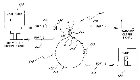
comprises the fiber switch architecture illustrated by a switch 400 in Figure
5A in
which ports 1, 2, 3 and 4 are labeled to correspond to the ports in Figure 2.
The
switch 400 comprises a Sagnac fiber interferometer 410. The interferometer 410
comprises a fiber loop 412 having a total length L and a first fiber coupler
414. The
first fiber coupler 414 is a four-port coupler which includes a port A, a port
B, a port
-16-
CA 02279758 1999-07-30
C and a port D. Loop ends are connected to port C and port D of the first
coupler
414. The first fiber coupler 414 couples approximately 50% of the light at the
signal
wavelength. A shorter active (e.g., doped) fiber 416 is placed asymmetrically
inside
the loop 412 and is positioned near the 3-dB coupler 414. Thus, the loop 412
comprises a length of the active fiber 416 and a length of inactive (i.e.,
undoped) fiber
418. Pump light from a pump source 420 is injected into the active fiber 416
by a
second coupler 422, which is a wavelength division multiplexing (WDM) coupler.
The second coupler 422 is coupled to the pump source 420 via a pump input
fiber 424
(port 2). The second (WDM) coupler 422 is configured to couple all the pump
light
into the loop 412. The second (WDM) coupler 422 is further configured to not
couple
the signal out of the loop 412 (i.e., the second (WDM) coupler 422 couples
substantially 0% of the light at the signal wavelength). The second (WDM)
coupler
422 is preferably positioned close to the active fiber 416 so that the pump
signal
propagates through very little of the undoped optical fiber 418. Thus, the
pump light
has little effect on the refractive index of the undoped optical fiber 418.
Rather,
substantially all of the effect of the pump light is concentrated in the
active fiber 416.
An input signal from a signal source 430 is transmitted via an input fiber 432
(port 1) to an optical circulator 434 and then via an input/output fiber 436
to port A
of the first coupler 414. For the purposes of the following discussion, it is
assumed
that the input signal is a continuous wave signal. The first coupler 414
launches the
signal light into the loop 412 from port C and from port D with substantially
equal
power in the two directions to cause the signal light to propagate in the loop
412 as
two counterpropagating light signals (a clockwise (CW) signal and a
counterclockwise
(CCW) signal). In the absence of pump light, the counterpropagating signals
experience the same phase delay around the loop 412. Thus, when the two
counterpropagating signals reenter the first coupler 414 via port C and port D
and are
recombined therein, the two signals destructively interfere at port B but are
recombined constructively at port A (i.e., the original input port). Thus, the
combined
signals are directed back through the input/output fiber 436 toward the
circulator 434.
The circulator 434 then directs the signal via an output fiber 440 which
functions as
-17-
CA 02279758 1999-07-30
an output port (port 3) for the unswitched output signal (i.e., the output
signal which
occurs when no pump signal is applied).
Note that the optical circulator 434 is a three-port device which operates in
a
well-known manner to cause substantially all the light entering through a
first port
(e.g., the port connected to the input fiber 432) to be coupled out of the
next adjacent
port (e.g., the second port connected to the input/output fiber 436). The
optical
circulator 434 is a unidirectional device, which means that the light
circulates in the
circulator 434 in one direction only (e.g., clockwise in Figure 4). Thus,
light which
returns from the Sagnac loop 412 in the fiber 436 and enters the second port
of the
circulator 434 is coupled to the third port and therefore to the output fiber
440. No
light enters the third port of the circulator 434. No light is coupled from
the
input/output fiber 436 back to the first port connected to the input fiber
432. The
circulator 434 thus operates as an isolator to isolate the input fiber 432
from the
input/output fiber 436. Similarly, the circulator 434 prevents light on the
input fiber
432 from being propagated directly to the output fiber 440. An exemplary
optical
circulator 434 is available from E-TEK Dynamics, Inc., 1885 Lundy Avenue, San
Jose, California 95131.
As will be discussed in more detail below, when a pump pulse from the pump
source 420 is applied via the second (WDM) coupler 422, the two
counterpropagating
light signals experience different phase shifts because of the effect of the
pump signal
on the active fiber 416 and because of the asymmetrical location of the active
fiber
416. Assuming that the differential phase shift is n or an odd multiple of n
(i.e.,
a phase shift of (2n+1)7r for n = 0, 1, 2, ...), the two signals interfere
destructively
in port A of the coupler 414 and interfere constructively in port B of the
coupler 414.
An output fiber 450 (port 4) couples the output signal from port B of the
coupler 414
as a switched output signal. In other words, the signal light is coupled to
the output
fiber 450 (port 4) as the result of the application of a pump signal pulse.
The operation of the active fiber 416 in providing the asymmetrical delay can
be understood from the following discussion. In the following discussion,
reference
is made to the transit time zL through the loop 412. It is assumed that the
total length
-18-
CA 02279758 1999-07-30
L of the loop 412 includes both the active fiber 416 and the undoped fiber 418
in the
loop 412. Thus, the transit time iL includes the propagation time through the
active
fiber 416 as well as the transit time through the undoped fiber 418 of the
loop 412.
It is further assumed that the length of the active fiber 416 is much, much
less than
the overall length of the loop 412. It should be noted that in alternative
embodiments,
the length of the active fiber 416 can be a substantial portion of the overall
length of
the loop 412 (e.g., up to less than one-half of the overall length), and the
present
invention will still work.
First, it is assumed that the dopant in the doped fiber 416 exhibits no
thermal
effects, and exhibits only nonlinearity. When using such an active fiber 416
in
conjunction with the present invention, both the rise time and the fall time
of the
nonlinear shift induced by the pump in the fiber are relevant to the switch
characteristics. The resonant nonlinearity is characterized by a response time
Tnl'
This parameter affects both the rise time and the fall time. Regarding the
fall time,
the physical meaning of inl can be understood as follows. A length of fiber
doped
with a nonlinear dopant is excited optically by a pump. After the pump is
turned off,
electrons in the excited state decay exponentially with a time constant equal
to Tnl
(i.e., the fall time of the phase shift is equal to inl).
The connection between ini and the rise time is more complex because the
pump power is involved. For the following discussion, it is assumed that the
pump
repetition rate is low and is smaller than about 1/tinl. In the case of low
peak pump
power where the peak pump power is smaller than or equal to the saturation
power
of the dopant in the fiber, as the pump pulse width ipump is increased from
zero while
keeping the peak pump power constant, at first the nonlinear phase shift 0~
induced
by the pump in the fiber at a given signal wavelength increases linearly with
tipump'
When tipump becomes equal to about inl, 0~ continues to grow but at a
sublinear rate
that decreases as ipump increases. When ipump reaches a few Tnl, the phase
shift 0~
reaches its maximum (or asymptotic) value and does not grow any more, even if
ipump
is further increased. In practice, the value of ipump for which the phase
shift 0~ has
reached its asymptotic value is often taken to be about 3Tnl. The rise time
irise of the
-19-
CA 02279758 1999-07-30
phase shift can thus be defined somewhere in the range of inl to 3Tnl. For the
purposes of the present application, inSe is defined as ini, at which time the
phase shift
has reached approximately 63% of its asymptotic value.
When the pump peak power is increased and the foregoing steps are repeated,
the phase shift rises faster and faster as the peak pump power increases. This
behavior is explained as follows. Assume that the pump energy is maintained
constant. Thus, as the pump pulse width is decreased, the peak pump power is
increased in the same ratio to keep the energy constant. As ipump is decreased
from
Tni, the energy delivered by the pump pulse to the dopant remains the same.
Consequently, the narrower pump pulse induces in the dopant substantially the
same
electronic population change as when ipump is equal to inl. Thus, the
nonlinear phase
shift induced by the pump pulse also remains the same. The difference is that
because
Tpump is now shorter, the time it takes for the phase shift to reach the same
value is
shorter (i.e., tirise is shorter and substantially equal to zpUmp). In
summary, the rise
time of the nonlinear phase shift decreases as the pump pulse width is
decreased while
keeping the pump energy constant.
For the following discussion, it is assumed that the nonlinearity of the
active
fiber 416 has a rise time irise much shorter than the transit time iL of the
light through
the loop 412. If, at an initial time (t=O), a high intensity (several
saturation intensities)
pump pulse with a width tipump much shorter than inSe is launched into the
loop 412
via the pump input fiber 424 and the second (WDM) coupler 422, the pump signal
will induce, on the scale of 2pump, a nonlinear index change in the active
fiber 416.
As mentioned above, it is assumed that the optical input signal is a
continuous wave
signal. It should be understood, however, that the present invention can be
adapted
for use with pulsed signals. Thus, at any time, the loop 410 is filled with
clockwise
propagating signal light and counterclockwise propagating signal light. In the
illustrated embodiment, the active fiber 416 is positioned in the loop 410
such that the
clockwise (CW) propagating signal light propagates through the active fiber
416
shortly after exiting the coupler 414 at port D and before propagating through
the
undoped fiber 418 in the loop 412, and such that the counterclockwise (CCW)
-20-
CA 02279758 1999-07-30
propagating signal light exits from port C of the coupler 414, propagates
through the
undoped fiber 418 of the loop 412 first and then propagates through the active
fiber
416 shortly before it reenters the coupler 414 via port D. Thus, the
counterclockwise
signal about to emerge from the loop 412 and enter port D exhibits a nonlinear
phase
change immediately following the activation of the pump pulse. However, the
clockwise signal that interferes with it at the coupler went through the
nonlinear fiber
iL earlier, when the fiber was not yet pumped, and it has experienced no
nonlinear
phase change. Consequently, there is a pump-induced differential phase change
A~
between the two interfering signals. The pump power is selected such that
A~=7r, and
io the two counterpropagating signals now constructively recombine in port 4
(i.e., the
total signal power has been switched from port 3 to port 4) and the combined
signal
is output on a switched output fiber 450 as a switched output signal.
The foregoing is illustrated in Figures 6A, 6B, 6C and 6D. When a pump
signal is applied to the interferometer, as illustrated by a pump pulse in
Figure 6A, the
pump pulse causes a rapid change in the refractive index of the active fiber
416.
Because, for the purpose of this discussion, it is assumed that the loop 412
has signal
light propagating in it at all times, both the clockwise propagating signal
light and the
counterclockwise propagating signal light see the change in the refractive
index and
undergo respective phase changes caused by the change in the refractive index
of the
active fiber 416. Because of the location of the active fiber 416 proximate to
port D
of the coupler 414, the counterclockwise propagating light signal having the
phase
change emerges from the loop active fiber 416 and enters port D of the coupler
414
shortly after its phase is changed by the change in the refractive index.
Thus, in
Figure 6B, the phase change ~~~cw of the counterclockwise propagating light
signal
is shown as occurring immediately after the beginning of the pump pulse with a
rise
time determined by the response of the active fiber 416 to the pump pulse.
(For the
purpose of this discussion, it is assumed that the lengths of the fiber from
the second
(WDM) coupler 422 to the active fiber 416 and the length of the active fiber
416 are
much, much less than the overall length of the loop 412, and the delays
through these
short lengths of fiber are not represented in Figures 6A-6D.) Although the
clockwise
-21-
CA 02279758 1999-07-30
propagating light signal also experiences an immediate phase change, the
clockwise
propagating light signal must propagate through the entire length of the
undoped fiber
418 in the loop 412 before any of the clockwise propagating light which
experienced
the phase change enters port C of the coupler 414. Thus, again ignoring the
relatively
short distance between the two couplers 414, 422, the phase change of the
clockwise
propagating light appears at port C of the coupler 414 at a time delayed by
the
propagation time iL of the loop 412, as illustrated in Figure 6C. During the
propagation time iL, the signal light from the loop 412 combining in the
coupler 414
comprises the counterclockwise propagating light signal which has experienced
the
phase change and the clockwise propagating light which passed through the
active
fiber 416 before the pump pulse was activated. Thus, during the time tiL, the
two
counterpropagating light signals combining in the coupler 414 have a
differential
phase shift. The intensity of the pump pulse and the length of the active
fiber 416 are
selected so that the differential phase shift is 7E. Thus, rather than
combining
constructively in port A of the coupler 414, the counterpropagating light
signals
combine constructively in port B of the coupler 414, and are therefore output
as a
switched signal therefrom, as illustrated by the flat portion of the pulse in
Figure 6D.
The present invention illustrated in Figure 5A automatically switches the
output
signal back to the original coupler port when the clockwise propagating signal
light
having the phase change reaches port C of the coupler 414. In particular, as
illustrated
in Figure 6C, the phase shift 0~Cw of the clockwise propagating light signal
arrives
at port C of the coupler 414 at the end of the delay time iL, at which time
the two
phase changes (Figures 6B and 6C) are substantially equal. Thus, at the end of
the
time iL, the two counterpropagating signals combine constructively at port A
of the
coupler 414 and substantially no light is output from port B of the coupler
414.
Thus, as illustrated in Figure 6D, the output signal switches off. By
adjusting the
length of the loop 412 (including the length of the active fiber 416), the
width of the
output pulse in Figure 6D can be controlled.
With respect to the fall time of the switch, it can be initially assumed that
the
index change returns to zero with a time constant inl (which is true unless
depumping
-22-
CA 02279758 1999-07-30
schemes are involved, as taught, for example, in J.W. Arkwright, et al., An
investigation of Q-switched induced quenching of the _ resonant nonlinearity
in
neodymium doped fibers, JOURNAL OF LIGHTWAVE TECHNOLOGY Vol. 14,
No. 1, January 1996, pp. 110-120), and that the time constant inI is much
greater than
TL. Then, at t=TL, the CW signal goes through the active fiber and undergoes
nominally the same phase shift as the CCW signal had iL earlier. Thus, the two
signals have nominally the same phase, and the signal returns to port A of the
coupler
414 and thence to the unswitched output fiber 440. An important feature of the
present invention is that even if the response is slow, the switch can be
turned off very
quickly provided that the transit time iL is sufficiently short (i.e., the
length of the
loop 412 is short). The foregoing assumes that the duration of the pump pulse
and
the time required for light to travel through the active fiber 416 are less
than the loop
transit time iL.
One limitation to the foregoing is that after t=TL, no other pump pulse should
be applied until t is equal to one to a few inl in order that the nonlinearity
may return
to zero. Applying a pump pulse earlier will not create the required index
change
(unless a higher pump power is applied) because the dopant's electrons are
still
partially in the excited state. Thus, the maximum switch repetition rate is
approximately 1 /tin1.
The basic condition that must be met is that the dopant has a very short
nonlinear rise time, namely irise iL. Advantageously, the length Lactive of
the active
fiber 416 is much, much less than the overall length L of the loop 412, namely
Lactive<<L. Since TL=nL/c, where c is the speed of light and n is the fiber
refractive
index, the length of the loop 412 must be sufficiently long to make TL much
greater
than iriSe. For example, if tirise = 1 nanosecond, a length must be selected
which is
at least equal to L=tirisec/n (with c;~-3x10g meters/second and n--1.45), or
0.21 meter.
A length of 1 meter would be suitable. However, if irise l microsecond, the
minimum length L becomes ~ze210 meters, which is becoming prohibitive if one
wants
to keep the size and cost of the switch low. Many of the nonlinear dopants
identified
and tested so far have fall times inl in the range of 100 microseconds to 1
millisecond.
-23-
CA 02279758 1999-07-30
With these, this proposed scheme will still work but repetition rates are
limited to 1-10
kHz. Again, the rise time can be shortened by pumping harder (i.e., delivering
the
same amount of energy in a shorter amount of time).
To summarize the foregoing, the exemplary embodiment uses a dopant with
a nonlinear response time in, as fast as possible (although a few milliseconds
would
work unless a very fast repetition rate is desired) and pumps the fiber 416
with a
sufficiently high pump peak power that the nonlinear index rise time iriSe is
as short
as possible. By selecting a loop delay zL longer than zrise, an
environmentally stable
switch can be produced with a rise time tirise, an on-time iL, a fall time
inj, and a
maximum repetition rate of approximately 1/in1.
The present invention will now be considered with respect to a dopant having
dominantly thermal effects. The rise time of the index change is now imposed
by
how fast heat is generated in the dopant. This depends on both the pump pulse
length
and the time constant of phonon generation. The latter depends on the dopant
spectroscopy, particularly the energy spacing between the levels involved in
the
nonradiative relaxation caused by clusters, but it can be very fast (i.e., in
the
nanosecond range or less). If the pump pulses are comparably short, the heat
will be
deposited in the fiber on a nanosecond scale or shorter. The rise time of the
signal
phase change, i.e., how fast the signal is switched to port B of the coupler
414, will
also be in this range. The first necessary condition for this to happen (i.e.,
for the
CCW signal to experience a negligible phase change during most of TL) is that
iL is
long compared to the rise time of the index change tirise, i.e., that iL--
nI./c>-crise= For
example, if Trise = 1 nanosecond, L must be at least approximately 21
centimeters.
A possible compromise may be to use a length twice this long or longer. The
second
necessary condition is that the length of the active fiber 416 in which the
thermal
effect takes place is much shorter than the total length of the loop 412
(i.e., the length
of the fiber 416 is much shorter than the sum of the length of the active
fiber 416 and
the undoped fiber 418).
To determine the effect of the fall time, it can be assumed that the loop has
a
transit time TL ith so that the primary cause of switching the output signal
back to
-24-
CA 02279758 1999-07-30
the unswitched port is the effect of the Sagnac loop. There are two regimes of
interest, namely low and high pump repetition rate. If the repetition rate is
low, i.e.,
if the time between consecutive pulses is larger than the thermal response
time ith0,
the fall time of the thermal index change will be the order of Tth0. (-rthe is
again used
herein to mean the fall time of the thermal index change when a single pump
pulse
is applied.) At time t=iL, the CCW signal reaches the active fiber 416 and
also
experiences a phase shift. Because iL tith, the pump-induced index change has
decayed minimally during the period t=irise to t=TL, and the phase shift
experienced
by the CCW signal is almost the same as that experienced iL earlier by the CW
signal. Thus, at the first coupler 414, for thL, the two recombining signals
have
experienced almost the same phase shift. Therefore, the two signals interfere
constructively in port A of the coupler, and the combined signal is output
from the
unswitched output fiber 440 (port 3). Again, the Sagnac architecture forces
the device
to be switched back at a rate that is fast compared to the fall time of the
active fiber.
In general, the rise time of the pump-induced phase change depends on the
length of the active fiber 416, on the temporal width of the pump pulse, and
on the
response time of the dopant. In the case of a purely thermal dopant, the
response time
of the dopant depends on the spectroscopy of the dopant and the pump
wavelength.
In the case of a nonlinear dopant, the response time of the dopant depends in
particular on the spectroscopy of the dopant and the peak pump power. In the
present
application, it is assumed that the length of the active fiber 416 is
sufficiently short
and the width of the pump pulses is sufficiently short that the rise time of
the phase
change is not limited by the length of the active fiber 416. Rather, the rise
time of
the phase change is primarily controlled by the rise time of the dopant.
Similarly,
although the fall time of the pump-induced phase change also depends on the
length
of the active fiber 416 and on the response time of the dopant, for the
purposes of the
present application, it is assumed that the length of the active fiber 416 is
sufficiently
short that the fall time of the phase change is primarily controlled by the
fall time of
the dopant.
-25-
CA 02279758 1999-07-30
Figure 5B illustrates an alternative embodiment to the embodiment of Figure
5A. In Figure 5B, like elements are identified as in Figure 5A. Unlike Figure
5A,
the embodiment of Figure 5B applies the pump pulse from outside the loop 412,
thus
eliminating the need for the coupler 422 in the loop 412. In particular, a
second
optical circulator 460 is inserted into the switched output fiber 450. The
second
optical circulator 460 has a first port at the left which receives light from
port B of
the coupler 414 and which transfers the light to a second port at the right,
which is
connected to port 4 so that the light is provided as the output signal as
before. A third
port of the second optical circulator 460, shown at the bottom, receives pump
light
from the pump input fiber 424 and transfers the pump light to port B of the
coupler
414. As discussed above in connection with the first optical circulator 432,
the second
optical circulator 460 circulates light in one direction only (e.g.,
clockwise) from one
port to the next port only. Thus, all of the pump light is provided to port B
of the
coupler 414, and all the output light from port B of the coupler 414 is
provided as the
switched output signal at port 4. Note that the coupler 414 is preferably a
wavelength
division multiplexing (WDM) coupler which couples 50% of the light at the
signal
wavelength and which couples 0% percent of the light at the pump wavelength.
Thus,
substantially all the pump light is coupled to the loop 412 to circulate in
the clockwise
direction, and therefore propagates in the active fiber 416 where it is
absorbed.
An alternative embodiment of the architecture of Figure 5B would be to reverse
the orientation of the arrow in the circulator 460 and inject the pump power
from the
pump source 420 at port 4. Another alternative embodiment would be to add a
WDM
coupler on port I and use it to inject the pump light from the pump source 420
into
the loop 410. The coupling ratio of the WDM coupler 414 at the pump wavelength
would then need to be 100% if it is desirable to have the pump pulse travel
through
the active fiber 416 before traveling in the undoped fiber 418.
It should be recognized that in the embodiments of Figures 5A and 5B it may
be desirable to minimize the Kerr phase shift induced in the undoped fiber
418. If
this is the case, this minimization can be implemented by launching the pump
in such
a way that the pump travels through the active fiber 416 (where it is at least
partially
-26-
CA 02279758 1999-07-30
absorbed) before it travels through the undoped fiber 418, as is, for example,
achieved
in the particular embodiment of Figure 5A. If the Kerr effect is weak compared
to
the phase shift in the active fiber 416, then the placement of the pump
injection port
is not critical. On the other hand, if the Kerr effect is strong compared to
the effect
of the active fiber 416, then the pump should be injected close to the active
fiber 416,
and into the active fiber 416 first.
The operation of the embodiments of Figures 5A and 5B is illustrated in
Figures 6A, 6B, 6C and 6D wherein Figure 6A illustrates an exemplary pump
signal
pulse applied to the Sagnac switch of Figure 5A or the Sagnac switch of Figure
5B;
Figure 6B illustrates the relative change in phase of the counterclockwise
(CCW)
propagating signal in response to the thermal effect of the pump signal pulse
of Figure
6A; Figure 6C illustrates the relative change in phase of the clockwise (CW)
propagating signal in response to the thermal effect of the pump signal pulse
of Figure
6A; and Figure 6D illustrates the switched output signal resulting from the
difference
in the relative phase changes of the clockwise and counterclockwise signals of
Figures
6B and 6C.
It should be understood that any pump-dependent mechanism that produces a
similar temporal phase change in the light propagating in the fiber can be
used to
implement the present invention by selecting a loop length such that the delay
tiL
through the loop should be longer than the rise time of the pump-dependent
mechanism causing the phase change and shorter than the fall time of the
mechanism.
The second case is for a high pump repetition rate, i.e., consecutive pump
pulses spaced by OTp<_Ttho. It has been shown that the fall time of the
thermal index
is then equal to Atp-irise, i.e., is shorter than under low-repetition rate
pumping. As
discussed above, if TL Dip, the Sagnac interferometer automatically turns off
the
switched output signal at a time equal to iL. Because, as discussed above, ith
decreases as the pump repetition rate increases, the repetition rate of the
switch
increases with the pump repetition rate. In practice, a high repetition rate
is difficult
to achieve because it requires a very high average pump power and a
correspondingly
high temperature rise of the fiber. (For example, a temperature rise greater
than 100 F
-27-
CA 02279758 1999-07-30
is easily achievable even with a moderate average pump power.) In practice, a
higher
repetition rate regime can be achieved with special fiber cooling
arrangements.
Note that the fall time should be sufficiently long that the clockwise signal
and
the counterclockwise signal experience substantially the same phase change
although
they pass through the active fiber 416 at times spaced apart by the loop
transit time
iL. If the phase shift caused by the thermal effect decays significantly
between the
time the counterclockwise signal passes through the active fiber 416 and the
time
when the corresponding clockwise signal passes through the active fiber 416,
the two
signals will experience different phase changes. The difference in phase
changes will
prevent the output signal from switching completely back to the unswitched
port 3.
Thus, the extinction ratio of the signal in the unswitched port 3 to the
signal in the
switched port 2 may not be adequate for some applications requiring a very
large
extinction ratio. It is therefore preferable to have the fall time be much
greater than
the loop transit time iL. There is therefore a trade-off between extinction
ratio and
repetition rate. In particular, longer fall times yield high extinction ratios
and lower
repetition rates, whereas shorter fall times yield lower extinction ratios and
higher
repetition rates.
As an application of the foregoing principle relating to the operation of the
switch and the dependence on pump power described earlier in the context of
the
present invention, the case of Nd3+ as the nonlinear dopant is considered. It
is
assumed that the thermal effect is small compared to the nonlinear effect
(e.g., for the
case when the pump wavelength is approximately 800 nanometers). The lifetime
of
the excited level for Nd3+ in silica. and thus ini, is typically in the
neighborhood of
400 microseconds. For a fiber exhibiting a strong optical confinement, the
saturation
power may be on the order of 5 milliwatts. If the fiber is pumped with pulses
having
a low duty cycle (small compared to 1/400 microseconds or approximately 2.5
kHz),
at a power level of 5 milliwatts, the rise time Trise of the nonlinear phase
shift is, with
the limitation discussed above, also in the range of 400 microseconds. Since
the delay
through the loop length 412 must be longer than tinse, a very long fiber on
the order
of at least 160 kilometers must be used. Because such a long fiber is
impractical, a
-28-
CA 02279758 1999-07-30
better utilization of the dopant is to pump the fiber at a much higher power
level, e.g.,
a hundred times higher. Specifically, pump pulses having a width of 4
microseconds
and having a peak power of 500 milliwatts can be used to provide the same pump
energy with significantly greater pump power. In such a case, the rise time is
reduced
to around 4 microseconds, and the minimum loop length required decreases by a
factor of 100 to about 1,600 meters.
Similar numerical calculations can be applied to other dopant materials. For
example, an optimized dopant advantageously has a minimum switching power
corresponding to a saturation power of 2 milliwatts, independently of its ini,
while in1
can, in principle, be no shorter than around a few nanoseconds (depending on
several
dopant parameters). In one example, if the dopant has a inl of 1 microsecond
and is
pumped with pump pulses having a peak power of 200 milliwatts and a pump width
ipump of 10 nanoseconds, the rise time inSe of the switch will also be 10
nanoseconds.
The minimum required fiber length will be very short (i.e., around 4 meters).
If a
fiber length of, for example, 4 meters is used and if the dopant length is
assumed to
be much shorter than 2 meters (as would be the case for such a dopant), the
switched
pulse width is 20 nanoseconds. This switched pulse width is much shorter than
inl
of 1 microsecond. The product of power and total length required for this
switch is
thus 0.2 watts times 4 meters (i.e., 0.8 watt-meters). The product of power
multiplied
by doped fiber length is even shorter-typically in the 0.1 to 1.0 watt-
millimeters
range. These products are considerably lower than the product required for any
silica
fiber Sagnac switches which rely on the Kerr effect, for which Kerr effect
switches
the power-length product is typically in the range of several hundred watt-
meters.
(See, N.J. Doran, et al., Experimental Investigation of All-Optical Switching
in Fibre
Loop Mirror Device, ELECTRONICS LETTERS Vol. 25, No. 4, 18th February 1989,
pp. 267-269; and M. Jinno, et al., Demonstration of laser-diode-pumped
ultrafast all-
optical switching in a nonlinear Sagnac interferometer, ELECTRONICS LETTERS,
Vol. 27, No. 1, 3rd January 1991, pp. 75-76.)
One of the advantages of the Sagnac switch 400 is its insensitivity to slow
external perturbations. How slow depends on the loop length L. For example, if
the
-29-
CA 02279758 1999-07-30
temperature of a portion of the loop 412 is modified by external heating on a
time
scale slower than tiL, the CW and CCW signals will experience nominally the
same
phase change and the switch output will remain unchanged. Similarly, the
Sagnac
switch 400 is insensitive to slow fluctuations in temperature gradients. Also,
if the
dopant exhibits thermal processes, the switch 400 is insensitive to variations
in steady-
state index change due to slow variations in pump power with respect to the
delay iL
through the loop 412.
A second advantage of the present invention, as discussed above, is that the
Sagnac switch 400 supplies an automatic mechanism to switch off the signal
very
rapidly even if the dopant nonlinearity itself has a long fall time. This
means that
many dopants which would be unusable in other interferometers can be used in
the
Sagnac switch 400.
A third advantage is that the on-time of the switch can be adjusted by
controlling the length L of the loop 412.
A fourth advantage of the present invention is that high dopant concentrations
can be used in a thermal Sagnac switch 400. High concentrations in silica-
based
glasses generally result in the formation of clusters, in which many dopant
particles
(e.g., ions) are adjacent instead of being evenly disseminated in the glass
matrix.
Unlike isolated ions, clustered ions are subject to cross-relaxation. Energy
between
clustered ions is exchanged, resulting in a loss of electronic population
change via
nonradiative mechanisms. This effect is detrimental to the nonlinear effect,
because
the nonlinear effect relies on the creation of a large population change with
as little
pump power as possible. Clusters increase the peak power required to obtain a
certain
level of population change, and thus decrease the nonlinear effect
contribution.
Similarly, clusters add nonradiative processes, i.e., increase the percentage
of absorbed
power turned into heat, which can be used to generate a thermal phase change.
To
be useful, the nonradiative time constant in clusters must be very short,
which is
generally true. (See, M.K. Davis, et al., Characterization of Clusters in Rare
Earth-
Doped Fibers by Transmission Measurements, JOURNAL OF LIGHTWAVE
TECHNOLOGY, Vol. 13, No. 2, February 1995, pp. 120-126.) Thus, a thermal
-30-
CA 02279758 1999-07-30
Sagnac switch 400 in accordance with the present invention can utilize a
heavily
doped active fiber 416, with the benefit that the fiber 416 can now be
shorter.
Therefore, the loop length L can be shorter, and the duration of the time
during which
the switch is on can be shorter.
A fifth advantage of the present invention is that unlike other
interferometers,
the Sagnac switch 400 does not require a short nonlinear fiber 416. So far,
the field
of resonant nonlinearity has been limited by the fact that fibers cannot be
heavily
doped because most dopants are poorly soluble in silica-based glasses. Thus,
long
fibers (on the order of 1 meter) are needed and the switches (e.g., Mach-
Zehnder
switches) are environmentally unstable. In the Sagnac switch 400 in accordance
with
the present invention, this restriction is completely removed, and many
dopants that
are not practical in other interferometers can be used in the Sagnac switch
400.
A sixth advantage of the present invention is that the switch operation
depends
very little to not at all on the pump polarization. When the thermal effect is
used, for
most dopants, absorption of the pump photons and conversion of the pump
photons
into heat occurs with the same efficiency and speed for any polarization of
the pump
light. This is highly advantageous, because in a fiber the state of
polarization of the
pump varies with environmental parameters, and, in particular, varies with
temperature
and pressure. In a Kerr-based fiber switch, unless, for example, a
polarization-
maintaining fiber is used to form the loop or an unpolarized pump is used, the
switching power needed to induce switching depends on external temperature,
pressure, etc. In the present invention, when the nonlinear effect is used,
the pump-
induced phase shift does depend on the relative polarization of the pump and
the
signal in the active fiber 416; however, the dependency is small, so that the
switching
power will depend very little on the pump polarization. (See, R.W. Keys, et
al.,
Polarization-Dependent Gain in Erbium-Doped Fibers, PROCEEDINGS OF THE
OPTICAL FIBER COIVIMUNICATION CONFERENCE OSA TECHNICAL
DIGEST SERIES NO. 4, 1994, pp. 306-307.)
A first embodiment of the present invention for the thermal Sagnac switch 400
utilizes an active fiber 416 doped with triply ionized samarium (Sm3+). This
dopant
-31-
CA 02279758 1999-07-30
presents a very broad absorption band above approximately 1.1 micron that is
very
strongly nonradiative. It is thus predicted that nearly 100% of the pump power
absorbed in this band is turned into heat, with a time constant in the
nanosecond
range, which means a fast rise time for the thermal index change. As explained
above, large concentrations (i.e., short fibers) are likely possible with such
dopants.
The pump source 420 is advantageously a laser diode at 1.48 microns, or an
approximately 1.55-micron or 1.3-micron fiber or semiconductor laser. The
signal
must be in a transparency region of the dopant, which, for samarium, is
advantageously in the 0.55-1.0 micron or 1.6-2 micron windows (approximately).
The
active fiber 416 advantageously comprises a few tens of centimeters (e.g., 20
centimeters) of fiber containing a few thousand mole parts per million (ppm)
(e.g.,
5,000 mole ppm) of Sm3+. The loop 412 has a total length L on the order of 1
meter
or even less, depending on the fall time required.
Other triply ionized rare earths can also be used for thermal switching. In
particular, terbium (Tb3+) or praseodymium (Pr3+) can be used. Tb3+ can be
pumped
at 1.6 microns with an Er-doped fiber laser, and will switch signals in a
range between
700 nanometers and 1400 nanometers. Pr3+ can be pumped at 1.48 microns with a
laser diode, and will switch signals in a range of 650 nanometers to 1200
nanometers.
A second embodiment for a thermal Sagnac switch 400 utilizes an active fiber
416 doped with a transition metal such as doubly ionized cobalt (Co2+), which
presents a strong and wide absorption centered around approximately 0.7 micron
that
is strongly nonradiative. Measurements indicate that approximately 30-40% of
the
absorbed pump power is turned into heat, with a-response time of 10
nanoseconds or
less. Co2+ absorbs strongly, and large concentrations of Co2+ are possible in
silica-
based glasses. For example, full absorption around 700 nanometers at high
powers
has been demonstrated in a 2-millimeter fiber doped with an approximately
10,600
weight ppm of Co2+. The pump is advantageously in the 700 nm range, and the
signal is advantageously in the relatively narrow transparency window of Co2+-
doped
silica around 830 nanometers. The active fiber 416 can be a few millimeters of
fiber
containing a few thousand weight ppm of Co2+. The loop must be of the order of
a
-32-
CA 02279758 1999-07-30
few meters so that iL exceeds the rise time (a few nanoseconds, depending on
pump
pulse width) of the thermal index change.
Other transition metals are possible. In particular, triply to quintuply
ionized
vanadium (V +) ions in silica-based glasses absorb strongly and broadly in the
900 nm
region. In particular, one exemplary fiber turned approximately 55% of the
pump into
heat. Ionized vanadium can be doped in silica with a sufficiently high
concentration
to enable use of millimeter length fibers. The absorption of ionized vanadium
generally decreases with increasing wavelength, and is low above approximately
1.5
microns. Thus, a Sagnac switch 400 with an active fiber 416 doped with ionized
vanadium can make a good switch in the 1.5-micron communication window. The
composition of the fiber core and/or the valence of the vanadium may be
advantageously adjusted, if necessary, to reduce the residual vanadium
absorption in
this region.
A third embodiment is a Sagnac switch 400 utilizing an active fiber 416 doped
with a dopant which exhibits a strong and fast nonlinear response time (e.g.,
under a
few tens of microseconds). Such dopants have not yet been identified, but
potential
candidates include divalent rare earths, such as, for example, divalent
thulium (Tm2+),
and color centers. A first preferred requirement for such a dopant is that its
nonlinearity should be relatively fast, which requires that it exhibits a
purely radiative
transition with a relatively high oscillator strength so that it does not
exhibit
nonradiative processes and its radiative lifetime is in the range of tens of
microseconds
or less. For example, if the dopant has a nonlinearity fall time of 10
nanoseconds, the
loop length L must be shorter than 2 meters.
A second preferred requirement of the third embodiment is that the dopant can
be pumped with a laser diode as the pump source 420 so that the Sagnac switch
400
can be compact. With current laser diode technology, an infrared transition is
preferable, although shorter wavelength laser diodes with suitably high powers
are
starting to appear commercially.
-33-
CA 02279758 1999-07-30
A third preferred requirement of the third embodiment is the absence of
nonradiative processes, which would otherwise induce an undesirable thermal
phase
change.
A fourth preferred requirement of the third embodiment is that the nonlinear
fiber 416 be not too long, i.e., that the transition has a high oscillator
strength and that
the dopant concentration is high enough. This requirement guarantees a shorter
loop,
thus providing a shorter on time. Again, length is not as critical because a
few meters
of nonlinear fiber 416 would still yield a switch fall time in the few tens of
nanoseconds range, which is adequate for many applications. However, to reap
the
full benefit from the nonlinearity of the fiber 416, which can have a fall
time as fast
as a few nanoseconds (e.g., approximately 5 nanoseconds), a loop length of
only 1
meter is desired, and preferably, the active fiber 416 should be much shorter
than 1
meter.
A fourth embodiment utilizes an active fiber which exhibits a relatively slow
nonlinear dopant that is pumped with a sufficiently high peak power that the
rise time
'Crise is sufficiently short for a practical loop length. For example,
neodymium (Nd3+)
has a radiative lifetime of about 400 microseconds and has little thermal
effect when
pumped around 800 nanometers. A fiber doped with neodymium can be pumped with
pump pulses having a duration of approximately 4 microseconds and having a
peak
power of 500 milliwatts so that the rise time is reduced to approximately 4
microseconds. The minimum loop length in such an embodiment is about 1,600
meters.
It should be understood that other glasses than silica-based glasses can be
used
in combination with the present invention. For example, fluorozirconate
glasses,
phosphate glasses, chalcogenides, tellurites, borates, and the like, may be
used. In
addition, the present invention may be combined with other waveguides, such
as, for
example, integrated optics waveguides.
This invention may be embodied in other specific forms without departing from
the essential characteristics as described herein. The embodiments described
above
are to be considered in all respects as illustrative only and not restrictive
in any
-34-
CA 02279758 1999-07-30
manner. The scope of the invention is indicated by the following claims rather
than
by the foregoing description. Any and all changes which come within the
meaning
and range of equivalency of the claims are to be considered within their
scope.
-35-