Language selection

Search

Patent 2279880 Summary

Third-party information liability

Some of the information on this Web page has been provided by external sources. The Government of Canada is not responsible for the accuracy, reliability or currency of the information supplied by external sources. Users wishing to rely upon this information should consult directly with the source of the information. Content provided by external sources is not subject to official languages, privacy and accessibility requirements.

Claims and Abstract availability

Any discrepancies in the text and image of the Claims and Abstract are due to differing posting times. Text of the Claims and Abstract are posted:

  • At the time the application is open to public inspection;
  • At the time of issue of the patent (grant).
(12) Patent: (11) CA 2279880
(54) English Title: MECHANICAL SPLICE FOR CRIMPING OPTICAL FIBRE
(54) French Title: EPISSURE MECANIQUE A SERTIR POUR FIBRE OPTIQUE
Status: Expired and beyond the Period of Reversal
Bibliographic Data
(51) International Patent Classification (IPC):
  • G02B 6/255 (2006.01)
  • G02B 6/38 (2006.01)
(72) Inventors :
  • LESUEUR, PHILIPPE (France)
  • LIEGEOIS, CHRISTIAN (France)
  • EGON, PHILIPPE (France)
(73) Owners :
  • PRYSMIAN ENERGIE CABLES ET SYSTEMES FRANCE
(71) Applicants :
  • PRYSMIAN ENERGIE CABLES ET SYSTEMES FRANCE (France)
(74) Agent: KIRBY EADES GALE BAKER
(74) Associate agent:
(45) Issued: 2006-08-01
(86) PCT Filing Date: 1998-01-29
(87) Open to Public Inspection: 1998-08-06
Examination requested: 2003-01-29
Availability of licence: N/A
Dedicated to the Public: N/A
(25) Language of filing: English

Patent Cooperation Treaty (PCT): Yes
(86) PCT Filing Number: PCT/FR1998/000164
(87) International Publication Number: WO 1998034137
(85) National Entry: 1999-07-29

(30) Application Priority Data:
Application No. Country/Territory Date
97/01003 (France) 1997-01-30

Abstracts

English Abstract


A splice for crimping optical fibers includes two half cylinders, a support
block and a
pressing block, which are mutually pressed by a crimping cylinder. The support
block is
provided with a longitudinal groove for receiving the stripped fiber and bears
capped edges.
The capped edges and stops are symmetrically mounted on either side of the
longitudinal axis
of the half cylinders and are designed for maintaining axis of the half
cylinders and are
designed for maintaining a small space between the two half cylinders in the
zone where they
are located.


French Abstract

L'épissure est constituée de deux demi-cylindres, un bloc support (1) et un bloc presseur (2), qui sont serrés l'un contre l'autre part un cylindre de sertissage (3). Le bloc support est pourvu d'une rainure longitudinale (11) destinée à recevoir la fibre dénudée. Il porte des talons (10). Le bloc presseur porte des butées (20), au niveau des talons. Les talons et butées, montés symétriquement de part et d'autre de l'axe longitudinal des demi-cylindres sont destinés à maintenir un petit écartement des demi-cylindres l'un par rapport à l'autre, dans la zone où ils sont situés. Application à l'épissurage de fibres optiques.

Claims

Note: Claims are shown in the official language in which they were submitted.

5
CLAIMS
1. An apparatus for splicing and stripping covered optical fibers placed end
to end,
comprising:
a support block having a flat diametral longitudinal face comprising:
a V-shaped longitudinal groove provided on at least an intermediate zone of
the flat
diametral longitudinal face and configured to receive the covered optical
fibers; and
a U-shaped longitudinal groove located in a central zone of the flat diametral
longitudinal face, the U-shaped longitudinal groove extending the V-shaped
longitudinal
groove of the intermediate zone and having edges separated by a distance less
than the
external diameter of the covered optical fibers to allow splitting of a
covering at the ends of
the covered optical fibers;
a clamping and splitting cover having a flat diametral longitudinal face; and
a deformable cylindrical crimping tube configured to engage the flat diametral
longitudinal face of the support block with the flat diametral longitudinal
face of the
clamping and splitting cover.
2. The apparatus of claim 1, wherein the flat diametral longitudinal face of
the support
block and the flat diametral longitudinal face of the clamping and splitting
cover include
recesses positioned symmetrical to each other to maintain a small gap between
the support
block and the clamping and splitting cover relative to each other.
3. The apparatus of claim 1, wherein the flat diametral longitudinal face of
the clamping
and splitting cover includes a V-shaped longitudinal groove in an area
corresponding to the
intermediate zone of the flat diametral face of the support block.
4. The apparatus of claim 1, wherein the clamping and splitting cover further
comprises
a raised section in an area corresponding to the central zone of the flat
diametral longitudinal
face of the support block.
5. The apparatus of claim 1, wherein the support block further comprises
inclined
surfaces at the ends of the support block configured to facilitate the
introduction of the
covered optical fibers.

6
6. The apparatus of claim 1, wherein the clamping and splitting cover further
comprises
inclined surfaces at the ends of the clamping and splitting cover configured
to facilitate the
introduction of the covered optical fibers.

Description

Note: Descriptions are shown in the official language in which they were submitted.


CA 02279880 2003-O1-29
MECHANICAL SPLICE FOR CRIMPING OPTICAL FIBRE
BACKGROUND OF THE INVENTION
The invention relates to a mechanical splice for the self stripping crimping
of two
covered optical fibers.
Systems exist for mechanically crimping single fibers or several fibers
originating
from cables or tapes which are to be joined. These systems consist of
immobilizing the
stripped ends of the optical fiber or optics in an assembly body, the clamping
of which will
hold the ends to each other. DE 39 25 826 describes a mechanical splice
composed of two
semicylinders constructed in symmetrical manner relative to their median
transverse plane
and clamped against each other by a crimping cylinder.
The invention proposes a simple and low-cost mechanical crimper, suited to the
self
stripping crimping of optical fibers.
SUMMARY OF THE INVENTION
A principal subject of the present invention thus relates to a mechanical
crimper
intended for the self stripping crimping of two covered optical fibers placed
end to end,
composed of two semicylindrical blocks constructed symmetrically relative to
their median
transverse plane and each having a flat longitudinal diametral face as well a
deformable
cylindrical crimping tube which clamps the semicylindrical blocks against each
another,
diametral face against diametral face, one of the semicylindrical blocks being
provided on at
least one part of the length of its flat diametral face, with a longitudinal V-
shaped groove
intended to receive the two covered fibers to be crimped, and the
semicylindrical blocks
carrying raised or recessed elements placed symmetrically on both sides of
their longitudinal
axis, elements which are intended to maintain a small gap between the
semicylindrical blocks
relative to each other, in the zones where these elements are located.
According to the
invention, one of the semicylindrical blocks has on each side of the median
plane an end zone
for the introduction of the covered fiber having an opening which widens to
the outside
which extends into the intermediate zone provided with said V-shaped groove
for receiving
the covered fiber, and a central zone bearing a U-shaped groove which extends
the V-shaped
groove, said U-shaped groove having edges separated one from the other by a
distance less
than the external diameter of the covered fibers, to allow the splitting of
the covering at the
end of the fibers.

CA 02279880 2003-O1-29
2
According to another characteristic, the other semicylindrical block forming a
clamping and splitting cover has an inclined face in the same end zone, a V-
shaped groove in
the same intermediate zone and a raised element forming a longitudinal thicker
section in the
same central zone.
BRIEF DESCRIPTION OF THE DRAWINGS
Other particular characteristics and advantages of the invention will become
apparent
from the following description of an embodiment in which reference will be
made to the
attached drawings which represent:
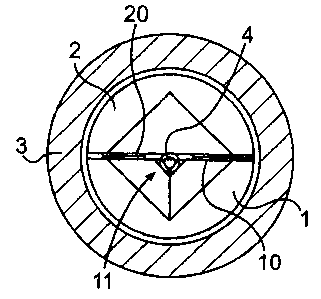
FIGS. 1 and 2, cross-sectional views of a mechanical splice according to the
prior art,
before and after crimping respectively.
FIGS. 3 and 4, plane and elevation views respectively of a semicylindrical
block
forming the support for the fibers.
FIGS. 5 and 6, enlarged cross-sectional views along V-V and VI-VI of FIG
respectively.
FIGS. 7 and 8, plan and elevation views respectively of a semicylinder forming
the
clamping and splitting cover for the self stripping of the fiber.
FIG. 9, an enlarged cross-sectional view along IX-IX of FIG. 8.
FIG. 10, a schematic cross-sectional view of a optical fiber in the self
stripping
crimping phase.
DETAILED DESCRIPTION OF THE PREFERRED EMBODIMENTS
FIG. 1 shows schematically a mechanical crimper known according to the prior
art for
a standard single fiber 4. This crimper is essentially composed of a support
block of
semicylindrical numbered 1 as a whole, a pressure block also of
semicylindrical section
numbered 2 as a whole and a crimping cylinder 3. The stripped fiber 4 is
placed in a V-
shaped groove 11 provided in the center of the diametral face of the support
block 1. On both
sides of this groove, i.e. on both sides of the longitudinal axis of the
semicylinder, the support
block is equipped with heels 10 forming a thicker section above this upper
face. The pressure
block 2 is placed above the support block 1, its lower face 21 being opposite
the upper face
14 of the support block. The pressure block also has shoulders 20 forming a
thicker section,
which are opposite the heels 10. The lower face of the pressure block is flat.
It should be
noted that the two blocks are wholly accommodated inside the crimping cylinder
3.

CA 02279880 2003-O1-29
When the two ends of the two optical fibers to be joined have been positioned
end to
end in groove 11, crimping is carried out by deforming the crimping cylinder 3
into a
hexagonal matrix. It can be seen in FIG. 2 that the two semicylinders 1 and 2
are clamped
against each other and in the central zone where the two fibers are in
contact, the deformation
of the support block and pressure block will cause the clamping of the optical
fiber between
the flat part of the pressure block and the V-shaped groove of the support
block.
FIGS. 3 and 4 show schematically a support block of semicylindrical section
according to the invention numbered 1 as a whole. FIGS. 7 and 8 show a
pressure block also
of semicylindrical section numbered 23 as a whole.
These blocks bear raised or recessed elements placed symmetrically on both
sides of
their longitudinal axis, elements which are intended to maintain a small gap
between the
semicylindrical blocks relative to each other in the zones where these
elements are located.
The support and pressure block assembly is covered by a crimping cylinder not
shown.
The support block 1 illustrated in FIGS. 3 and 4 shows a particular embodiment
of
one of the semicylindrical blocks in the case of a splice intended for the
self stripping
crimping of two optical fibers. It is constructed symmetrically relative to
its median
transverse plane M. A first zone A for introducing the fiber is found on each
side. This
opening connects to a V-shaped groove 11 which extends over a length B, the
groove being
centered on the axis of the semicylindrical block.
In the central zone C, the V-shaped groove is extended by a U-shaped groove
17, the
edges 18 of which receive a fiber 4 with its covering 6, as is seen more
clearly in FIGS. 5 and
6. In FIGS. 7 and 8, a clamping and splitting cover 23 is represented with its
zones A, B and
C corresponding to those of the support block. In zone A, an inclined face 24
encourages the
introduction of the covered fiber. Zone B has a V-shaped groove 11, but the
central zone of
the cover (zone C) is provided with a longitudinal thicker section 25. The
particular shape of
this thicker section 25 is seen more clearly in FIG. 9. When the splice is
assembled, the
inclined face 24 of zone A together with the support block 1 forms an entrance
for the
introduction of the optical fiber.
The corresponding parts of zone B, when they are assembled, form the part in
which
the covering of the optical fiber rests.
When the non-stripped fibers are introduced into the splice, they come to rest
in zone
C between the U-shaped groove 17 of the support block 1 and the thicker
section 25.

CA 02279880 2003-O1-29
4
After crimping, the covering of the fiber is "split" by the edges 18 of the
groove 17 as
illustrated in FIG. 10. The stripped part of the fiber is then positioned
between these two
edges whilst the split covering 6 is pushed away to the sides. The stripped
fiber is then held in
position by the thicker section 25.

Representative Drawing
A single figure which represents the drawing illustrating the invention.
Administrative Status

2024-08-01:As part of the Next Generation Patents (NGP) transition, the Canadian Patents Database (CPD) now contains a more detailed Event History, which replicates the Event Log of our new back-office solution.

Please note that "Inactive:" events refers to events no longer in use in our new back-office solution.

For a clearer understanding of the status of the application/patent presented on this page, the site Disclaimer , as well as the definitions for Patent , Event History , Maintenance Fee  and Payment History  should be consulted.

Event History

Description Date
Time Limit for Reversal Expired 2017-01-30
Letter Sent 2016-01-29
Inactive: Correspondence - Transfer 2008-01-28
Letter Sent 2007-08-21
Inactive: Multiple transfers 2007-06-19
Grant by Issuance 2006-08-01
Inactive: Cover page published 2006-07-31
Inactive: Final fee received 2006-05-12
Pre-grant 2006-05-12
Inactive: IPC from MCD 2006-03-12
Notice of Allowance is Issued 2005-12-01
Letter Sent 2005-12-01
Notice of Allowance is Issued 2005-12-01
Inactive: Approved for allowance (AFA) 2005-11-01
Letter Sent 2003-03-12
Request for Examination Requirements Determined Compliant 2003-01-29
All Requirements for Examination Determined Compliant 2003-01-29
Amendment Received - Voluntary Amendment 2003-01-29
Request for Examination Received 2003-01-29
Letter Sent 2000-05-11
Inactive: Single transfer 2000-04-10
Letter Sent 2000-03-16
Reinstatement Requirements Deemed Compliant for All Abandonment Reasons 2000-03-06
Deemed Abandoned - Failure to Respond to Maintenance Fee Notice 2000-01-31
Inactive: Cover page published 1999-10-13
Inactive: First IPC assigned 1999-10-07
Inactive: Courtesy letter - Evidence 1999-09-14
Inactive: Notice - National entry - No RFE 1999-09-13
Application Received - PCT 1999-09-10
Application Published (Open to Public Inspection) 1998-08-06

Abandonment History

Abandonment Date Reason Reinstatement Date
2000-01-31

Maintenance Fee

The last payment was received on 2006-01-11

Note : If the full payment has not been received on or before the date indicated, a further fee may be required which may be one of the following

  • the reinstatement fee;
  • the late payment fee; or
  • additional fee to reverse deemed expiry.

Please refer to the CIPO Patent Fees web page to see all current fee amounts.

Owners on Record

Note: Records showing the ownership history in alphabetical order.

Current Owners on Record
PRYSMIAN ENERGIE CABLES ET SYSTEMES FRANCE
Past Owners on Record
CHRISTIAN LIEGEOIS
PHILIPPE EGON
PHILIPPE LESUEUR
Past Owners that do not appear in the "Owners on Record" listing will appear in other documentation within the application.
Documents

To view selected files, please enter reCAPTCHA code :


To view images, click a link in the Document Description column. To download the documents, select one or more checkboxes in the first column and then click the "Download Selected in PDF format (Zip Archive)" or the "Download Selected as Single PDF" button.

List of published and non-published patent-specific documents on the CPD .

If you have any difficulty accessing content, you can call the Client Service Centre at 1-866-997-1936 or send them an e-mail at CIPO Client Service Centre.


Document
Description 
Date
(yyyy-mm-dd) 
Number of pages   Size of Image (KB) 
Representative drawing 1999-10-13 1 7
Description 2003-01-29 4 195
Claims 2003-01-29 2 59
Abstract 2003-01-29 1 16
Drawings 2003-01-29 4 75
Claims 1999-07-29 1 54
Abstract 1999-07-29 1 66
Description 1999-07-29 4 175
Drawings 1999-07-29 3 62
Cover Page 1999-10-13 1 44
Representative drawing 2005-11-16 1 10
Cover Page 2006-07-05 1 41
Reminder of maintenance fee due 1999-09-30 1 114
Notice of National Entry 1999-09-13 1 208
Courtesy - Abandonment Letter (Maintenance Fee) 2000-02-28 1 185
Notice of Reinstatement 2000-03-16 1 171
Courtesy - Certificate of registration (related document(s)) 2000-05-11 1 113
Reminder - Request for Examination 2002-10-01 1 116
Acknowledgement of Request for Examination 2003-03-12 1 185
Commissioner's Notice - Application Found Allowable 2005-12-01 1 161
Maintenance Fee Notice 2016-03-11 1 171
Correspondence 1999-09-13 1 14
PCT 1999-07-29 29 1,162
Fees 2000-03-06 1 54
Correspondence 2006-05-12 1 38