Note: Descriptions are shown in the official language in which they were submitted.
CA 02280222 2003-10-06
Docket No.: RHAC-0128
ROOF CURB APPARATUS
BACKGROUND OF THE INVENTION
The present invention generally relates to heating and air conditioning
equipment and, in a preferred embodiment thereof, more particularly relates to
roof
curbs used to underlie and operatively support heating and air conditioning
units on a
roof.
Frame-shaped structures commonly referred to as roof curbs are typically used
to support heating and air conditioning units on roofs to supply heated or
cooled air to
conditioned spaces below the roof. The typical roof curb has a rectangular
frame
body portion which is comprised of four side wall portions which are secured
together
at the job site, the assembled body portion extending above the roof and
forming a
base structure upon which a heating and air conditioning may be operatively
placed.
As conventionally assembled, the four side wall portions of the curb are
bolted
or screwed together at the corners of the curb, with all of the fasteners
being manually
put into place at the job site. As is well known in the industry, this
traditional method
of constructing a roof curb is a time-consuming and relatively expensive task.
A previously proposed solution to these problems associated with the use of
threaded fasteners to intersecure the side wall portions at the corners of a
roof curb is
' illustrated and described in U.S. Patent 5,148,647 to Rutledge in which a
hinge-like
structure is integrally formed on the ends of the roof curb side wall portions
and
CA 02280222 1999-08-13
configured to be joined together with pin structures driven into the hinge
structures at
the four corners of th.e roof curb. While this hinge/pin corner joining
structure tends
to speed up the overall roof curb assembly process, the pins used in securing
the
corners, as well as the formation of the hinge joints at the side wall ends,
tend to be
undesirably expensive. Moreover, the hinge portions on the contiguous curb
side wall
portion ends must be precisely aligned by hand to properly receive the pin
driven into
the hinge portions.
In view of these problems, limitations and disadvantages typically associated
with conventional techniques for assembling roof curbs it can readily be seen
that a
need exists for further improvements in such assembly techniques. It is to
this need
that the present invention is directed.
SUMMARY OF THE INVENTION
In carrying out principles of the present invention, in accordance with a
preferred embodiment thereof, quick assembly roof curb apparatus is provided
that
comprises a frame body structure including first and second side wall portions
each
having a length and an end. These first and second side wall portions are
positionable
in an assembly orientation in which their ends are in a contiguous
relationship, with
the side wall portions representatively being at a right angle to each other.
The first and second side wall portions, which are useable with two other side
wall portions to form a rectangular frame of the overall roof curb, carry
spaced first
connector structures, representatively inwardly lanced portions, adjacent the
ends
thereof. These first connector structures, with the first and second side wall
portions
being in their assembly orientation, are grouped in a first pair disposed on
opposite
sides of the contiguous side wall portion ends, and a second pair disposed on
opposite
sides of the contiguous ends and being spaced from the first pair in a first
direction
transverse to the lengths of the first and second side wall portions.
A specially dcaigned connector member, representatively in the form of a
plate-shaped drive cleat, is provided and is useable to lock the first and
second side
wall portions in their assembly orientation. The connector member has spaced
first
-2-
CA 02280222 1999-08-13
and second pairs of second connector structures thereon, representatively tab
members, which are positioned and configured to be sequentially and
interlockingly
engaged with the first and second pairs of first connector structures,
respectively, in
response to an operative movement of the connector member relative to the
first and
second side wall por~:ions in the aforementioned direction transverse to the
lengths of
the first and second side wall portions.
Because of the relative spacings between the pairs of first and second
connector structures which provides for this sequential engagement, only one
pair of
first connector structures and one pair of second connector structures need to
be
aligned with one another prior to the connector member being driven home. This
serves to make the connection of the frame side wall portions to one another,
and thus
the assembly of the overall roof curb, easier and faster.
According to another .feature of the invention, a detent structure is formed
on
at least one of the second connector structures to releasably hold it in
operative
locking engagement with its associated first connector structure.
Additionally, a
cross-piece structure is preferably secured to the assembled frame body
structure
using lanced portions of the side wall portions that receive tab portions of
the cross-
piece structure.
In a preferred embodiment thereof, the drive cleat has a generally plate-
shaped
body portion having top and bottom ends spaced apart in a first direction, and
first and
second spaced apart vertical side edge portions on which bottom, vertically
intermediate and top pairs of downwardly projecting connector tabs are formed,
the
tabs being receivable in corresponding slots in lanced portions of the frame
side wall
portions. The lanced portions are arranged in vertically spaced bottom,
vertically
intermediate and top pairs on the first and second side wall portions of the
frame,
representatively at a corner thereof. The lanced portions in each pair thereof
are
vertically aligned with one another and are each positioned on a different
side wall
portion end. The vertical spacing between the bottom lance pair and the
vertically
-3-
CA 02280222 1999-08-13
intermediate lance pair is equal to the vertical spacing between the
vertically
intermediate lance pair and the top lance pair.
The cleat tabs in each pair thereof are positioned on different ones of the
first
and second cleat body side edges, with the bottom ends of the vertically
intermediate
tab pair being vertically spaced apart from the bottom ends of the bottom
cleat pair a
first distance greater than the vertical lance pair-to-pair spacing, and the
bottom ends
of the top tab pair being vertically spaced apart from the bottom ends of the
vertically
intermediate tab pair a second distance greater than the first distance. In
this manner,
only the bottom tab pair of tabs need to be aligned with the bottom pair of
lances
before the cleat is driven home to cause the sequential and respective receipt
of the
bottom, vertically intermediate and top cleat tabs within the slots of the
bottom,
vertically intermediate and top lance pairs.
The drive cleat representatively has an angled body and is used at the corners
of a rectangular roof curb frame. It could, however, have a generally planar
body and
be used to join roof curb frame side wall sections in an end-to-end
relationship in
which the lengths of these side wall sections were essentially parallel to one
another.
Additionally, while the unique sequential engagement of the drive cleat
connector structures with the roof curb frame side wall portion connector
structures is
representatively achieved using equal vertical spacing between the side wall
portion
connector structure pairs and unequal vertical spacing between the drive cleat
connector structure pairs, it will be appreciated by those of skill in this
particular art
that these spacing relationships could be reversed so that the vertical
spacing between
the drive cleat connector structure pairs was equal, with the vertical spacing
between
the frame side wall portion connector structure pairs being unequal.
In another preferred embodiment of the invention, one side of the drive cleat
structure is anchored to, and preferably formed integrally with the end of one
of the
first frame side wall portion and has outer side edge tabs which are
sequentially
engageable with the lanced connector structures on the end of the second side
wall
-4-
CA 02280222 1999-08-13
portion. Preferably, this side portion of the drive cleat structure projects
transversely
outwardly from the e,nd of the first side wall portion.
BRIEF DESCRIPTION OF THE DRAWINGS
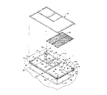
FIG. 1 is a partially exploded perspective view of a roof curb assembly
incorporating therein, at its corner joints, a specially designed multi-tab
drive cleat
embodying principles of the present invention;
FIGS. 2A and 2B are enlarged scale perspective detail views of the dashed line
area "2" in FIG. 1 and sequentially illustrate the installation of the tabs of
one of the
corner drive cleats in associated lance slot portions of contiguous side wall
panel
sections of the roof curb;
FIG. 3 is an enlarged scale perspective view of an end portion of one of the
curb cross pieces sha~wn in FIG. 1;
FIG. 4 is an enlarged scale cross-sectional view through the cross piece end
portion taken along line 4-4 of FIG. 1; and
FIG. 5 is an enlarged scale perspective detail view similar to FIG. 2A but
illustrating the use of an alternate embodiment of the drive cleat in which a
horizontal
side portion thereof is formed integrally with one of the side wall panel
sections of the
roof curb.
DETAILED DESCRIPTION
Referring initially to F'IG. l, the present invention provides a specially
designed quick assembly roof curb 10 which is used to underlie and operatively
support, for example., a heating and air conditioning unit (not illustrated)
on a roof 11
to provide heated or cooled air, as needed, to a conditioned space beneath the
roof.
Roof curb 10 includes a rectangular frame 12 having corners 12a and being
defined by
four elongated metal panel members 14a-14d which are joined at the frame
corners
12a by four specially designed drive cleat fasteners 16 as later described
herein.
Each of the rr~etal side wall panel portions 14a-14d has a vertically oriented
body portion with an inner side 18, a horizontally outwardly extending top
edge
flange 20, and a horizontally outwardly extending bottom edge flange 22. Each
of the
-5-
CA 02280222 1999-08-13
flanges 20,22 is mitered at its opposite ends, as at 24. With the frame 12 in
its
assembled state, the bottom panel flanges 22 rest on supporting joists or
beams (not
shown) below the roof 11, and the top flanges 20 are disposed somewhat above
the
top surface of the roof 11. Wood miler strips 26 are suitably secured to the
outer side
surfaces of the panels 14a-14<I, just below the top edge flanges 20, and serve
as
nailing bases for adjacent flashing and counterflashing portions of the
overall roof
structure.
As later described herein, horizontal frame cross pieces 28,30,32 are secured
within a top interior side portion the frame 12 and define at the top side of
the roof
curb 10 a return air opening 34, a supply air opening 36, and a condenser
mounting
area 38 at the right end of the roof curb 10. A rectangular gasket structure
40 is
positioned atop the top edge flanges 20 and the cross pieces 28, 30 and 32,
and a
conventional insulation panel 42 is placed over the condenser mounting area
38. The
heating and air conditioning unit (not shown) is suitably supported on the top
side of
the assembled roof curb 10, with its supply air outlet opening over the roof
curb
opening 36, its return air inlet opening over the roof curb opening 34, and
its
condenser portion over the insulation panel 42.
FIGS. 2A and 2B show the drive cleat 16 used at the corner 12a formed by
facing ends of the two panel members 14a and 14d in their pre-assembly
orientation.
FIG. 2A illustrates th.e drive cleat 16 just prior to its locking engagement
with the
facing ends of panel :members 14a and 14d, and FIG. 2B illustrates the drive
cleat 16
after it has been installed on the facing ends of panel members 14a,14d and
releasably
locks them together.
Adjacent their facing ends, each panel member 14a,14d has three vertically
spaced, horizontally oriented lance portions projecting inwardly from its
inner side 18
- a bottom lance portion 44a, a vertically intermediate lance portion 44b, and
an upper
lance portion 44c. E;~ch lance portion 44a,44b,44c forms a tab slot S between
the
lance portion and the inner side 18 of its associated panel member 14a or 14d.
As
illustrated in FIG. 2A,, the bottom lance portions 44a are disposed in a
vertically
-6-
CA 02280222 2004-04-21
aligned pair on opposite sides of their associated frame corner 12a, the
vertically
intermediate lance portions 44b are disposed in a vertically aligned pair on
opposite
sides of their associated frame corner 12a, and the upper lance portions 44c
are
disposed in a vertically aligned pair on opposite sides of their associated
frame corner
12a. The vertical spacing between the pair of bottom lance portions 44a and
the pair
of vertically intermediate lance portions 44b is identical to the vertical
spacing
between the pair of vertically intermediate lance portions 44b and the pair of
upper
lance portions 44c.
The drive cleat 16 illustrated in FIGS. 2A and 2B is typical of the four drive
cleats used in the rectangular roof curb 10 and has a right angled, plate-
shaped,
vertically elongated body 46 that longitudinally extends parallel to the drive
axis of
the cleat and has, on each vertical outer side edge thereof, three vertically
spaced apart
depending fastening tabs which are horizontally aligned with one another - a
bottom
tab 48a, a vertically intermediate tab 48b, and an upper tab 48c. As
illustrated, the
bottom tabs 48a are disposed in a vertically aligned pair on opposite side
edges of the
cleat body 46, the vertically intermediate tabs 48b are disposed in a
vertically aligned
pair on opposite side edges of the cleat body 46, and the top tabs 48c are
disposed in a
vertically aligned pair on opposite side edges of the cleat body 46.
The tab pairs 48a,48b,48c are respectively and slidably insertable downwardly
into the slots S of the lance portion pairs 44a,44b,44c. For purposes later
described
herein, the vertical distance between the bottom ends of the pair of bottom
tabs 48a
and the bottom ends of the pair of vertically intermediate tabs 48b is greater
than the
vertical distance between the top sides of the pair of bottom lance portions
44a and the
top sides of the pair of vertically intermediate lance portions 44b, and the
vertical
distance between the bottom ends of the pair of vertically intermediate tabs
48b and
the bottom ends of the pair of top tabs 48c is greater than the vertical
distance between
the bottom ends of the pair of vertically intermediate tabs 48b and the bottom
ends of
the pair of bottom tabs 48a.
CA 02280222 1999-08-13
To perpendicularly join the adjacent pair of ends of the panel side wall
members 14a,14d at their associated frame corner 12a, the facing mitered ends
of the
two panel members il 4a,14d ~~re placed in an abutting relationship, and the
drive cleat
16 is interiorly positioned at the corner 12a with the lower ends of the
bottom drive
cleat tabs 48a (see FIG. 2A) just above the bottom lance portions 44a. The
drive cleat
16 is then longitudinally driven downwardly from its FIG. 2A starting position
to its
FIG. 2B installed po:>ition to respectively drive the cleat tab pairs
48a,48b,48c into the
slots S of their associated underlying lance portion pairs 44a,44b,44c and
releasably
lock the two panel members 14a,14d together at their facing ends. The three
other
drive cleats 16 are used in similar manners at the other three frame corners
12a.
Because of the unique vertical tab spacing of the drive cleat 16 relative to
the
vertical spacing of the lance portions 44a,44b and 44c, the drive cleat tab
pairs
48a,48b,48c sequentially enter the slots S of the lance portion pairs
44a,44b,44c as the
cleat 16 is driven from its FICi. 2A position downwardly to its FIG. 2B
installed
position. Accordingly, only the bottom two cleat tabs 48a need to be initially
aligned
with their associated lance portions 44a before the cleat 16 is pounded home.
The
initial alignment of the tabs 48a and lance portions 44a automatically aligns
the
remaining tabs with l:he remaining lance portion slots S as the tabs 48b
approach their
underlying lance portions 44b, and the tabs 48c later approach their
underlying lance
portions 44c. This substantially simplifies and quickens the installation of
each drive
cleat 16, in turn simplifying and quickening the overall assembly of the roof
curb 10.
Once each driive cleat 16 is downwardly driven into its FIG. 2B installed
position, dimples 50 formed on sides of each of the cleat's upper tabs 48c
pass
downwardly through and past their associate upper lance portions 44c and then
function as resilient detent-type holding structures that releasably retain
the installed
drive cleat 16 in place. If desired, this installed drive cleat holding
structure may be
augmented by self tapping screws 52 which are passed through holes 54 in the
drive
cleat 16 and threaded. into underlying portions of the joined side wall panel
members
l4a,l4d.
_g_
CA 02280222 1999-08-13
Referring now to FIGS. 1, 3 and 4, to further quicken and simplify the
assembly of the roof curb 10, various additional inwardly projecting lance
portions 56
are formed in selected. locations on the panel members 14, adjacent their
upper side
edge flanges 20, and define tab-receiving slots S within the interior of the
frame 12.
These additional lance portions 56 are used to facilitate the rapid attachment
of the
cross-piece structure :?8,30,32 to the frame 12.
FIGS. 3 and 4 illustrate the manner in which a portion of the cross-piece
structure 28,30 and 3:?, representatively a right end portion of the cross-
piece member
28, is attached to one of the auxiliary lance portions 56 in panel member 14a.
As
illustrated, the cross-piece 28 has an elongated rectangular top side wall 58
having a
pair of downturned side edge flanges 60 and 62, and a downturned end flange
64.
End flange 64, at its left and right sides (as viewed in FIG. 3) is notched to
formed a
downturned central connection tab 66. A similar tab is formed on the opposite
end of
the cross-piece 28. After the frame 12 has been assembled, the cross-piece end
tab 66
is simply slipped dovvnwardly into the slot S of the lance portion 56 (see
FIG. 4), with
other cross-piece end tabs being similarly slipped into other lance portions
56, to
rapidly and easily connect the cross-piece structure to the frame 12.
As can be readily seen from the foregoing, the use of the specially designed
drive cleats 16 makes the assembly of the roof curb frame 12 a quite simple
and rapid
operation. The fabrication of the cleats 16 and the lance structures 44 and 56
may be
economically achieved using simple metal stamping processes. Additionally, the
use
of the dimples 50 releasably retains the drive cleats 16 in place, but at the
same time
permits the easy removal of the cleats by simply moving one panel member 14
vertically relative to a contiguous panel member 14 at one of their corner
joints 12a.
Also, as previously mentioned, the use of the auxiliary lance portions 56
speeds up
and simplifies the installation of the cross-piece structure 28,30,32.
While the relative spacing between the drive cleat tab pairs 48a,48b,48c and
the associated lance portion pairs 44a,44b,44c which permits the tab pairs
48a,48b,48c
to respectively and sequentially enter the slots S of the lance portion pairs
44a,44b,44c
_g_
CA 02280222 1999-08-13
is preferably achieved using uniform vertical spacing between the lance
portion pairs
44a,44b,44c and using nonuniform vertical spacing between the drive cleat
pairs
48a,48b,48c, it will be appreciated that this sequential insertion result
could also be
achieved using a uniform tab pair vertical spacing and a nonuniform lance pair
vertical spacing scheme. Furthermore, this relative spacing and sequential
engagement between first and second connector structure pairs could also be
achieved
using first and second interengageable connector structures having
configurations
different than the illustrated tab and slot configurations respectively used
on the drive
cleat and the side wall panel portions of the roof curb frame 12.
An alternate embodiment 16a of the previously described drive cleat fastener
structure 16 is perspectively illustrated in FIG. 5. In this drive cleat
embodiment, a
horizontal side portion 46a of the drive cleat body 16 ~is formed integrally
with and
transversely projects outwardly from the illustrated end of the metal panel
member
14d, with the depending outer side edge tabs 48a,48b,48c on the integral drive
cleat
body portion 46a being downwardly and sequentially receivable in the slots S
of the
lance portions 44a,4~1b,44c on the panel member 14a as the cleat end of the
panel
member 14d is driven downwardly relative to the panel member 14a as
illustrated by
the arrow 68 in FIG. 5. As previously described for the separate drive cleat
16, the
passage of the dimple 50 on the cleat tab 48c releasably retains the ends of
illustrated
panel members 14a,14d in their aligned, assembled relationship.
The foregoing; detailed description is to be clearly understood as being given
by way of illustration and example only, the spirit and scope of the present
invention
being limited solely by the appended claims.
-10-