Note: Descriptions are shown in the official language in which they were submitted.
CA 02280247 2007-03-05
AUXILIARY HYDRAULIC DRIVE FOR TRACTORS
BACKGROUND OF THE INVENTION
This invention relates generally to four wheel drive articulated tractors
and, more particularly, to improvements to the drive system for
hydrostatically
driven tractors.
It is desirable to integrate all the drives for the input driven components
of an articulated four wheel drive tractor into a single gearbox affixed to
the
rear axle housing of the tractor. Such a mechanism would place the hydrostatic
pump for powering the traction drive of the tractor, the hydraulic pump for
the
tractor hydraulic system, the drive for the power-takeoff (PTO) system, and
any
auxiliary hydraulic pumps to be driven off the same gearbox device with the
output driver components, including the hydrostatic motor, speed reduction
gears and output drive shafts.
Lubrication of a gear set is a consideration is the design of a gearbox
device for transferring rotational power through gear sets arranged and
configured to provide the proper rotational speed to a component driven from
the engine of the tractor. Commonizing lubrication sumps can minimize the
number of lubrication systems that need to be provided as well as provide more
effective lubrication of the gear sets and the cooling of the lubrication
fluid.
Conventional tractor drive mechanisms include a mechanical
transmission to provide different output speeds for a given engine input
speed.
Even hydraulically driven tractors have utilized a three speed mechanical
transmission between the engine and the hydrostatic pump to provide desired
different input speeds to the operation of the hydrostatic pump for powering
the
CA 02280247 1999-08-12
-2-
movement of the tractor. It would be desirable to replace the three speed
mechanical transmission on hydrostatically driven tractors to minimize cost
and
to enhance operation of the tractor.
The gearbox would preferably be configured to mount the auxiliary
pump drive mechanism in an optional manner so that the auxiliary pump could
be added to the gearbox, if desired, and be driven therefrom.
SUMMARY OF THE INVENTION
It is an object of this invention to integrate the drive mechanisms for a
hydrostatically driven, four wheel drive tractor in which all the drives are
driven from a single splitter gearbox.
It is a feature of this invention that the splitter gearbox is affixed to the
rear axle housing of the tractor.
It is an advantage of this invention that the mounting of the splitter
gearbox to the rear axle housing allows the splitter gearbox and the rear axle
housing to share a common oil sump.
It is another advantage of this invention that the mounting of the splitter
gearbox to the rear axle housing reduces complexity.
It is another object of this invention to drive the front and rear axles of a
four wheel drive tractor from a variable displacement hydrostatic motor.
It is another feature of this invention that a hydraulically driven tractor
need not have a conventional transmission in order to obtain customary speed
ranges desired for a tractor.
It is still another feature of this invention that the variable displacement
hydrostatic motor can be provided with a selected number of pre-set swash
plate positions to effectively replace a conventional transmission gearbox.
It is another advantage of this invention that the fixed positions of the
variable displacement hydrostatic motor, coupled with a variable speed
CA 02280247 1999-08-12
-3-
hydraulic pump, can be controlled electronically to provide a smooth
power-shifting operation.
It is still another advantage of this invention that the tractor does not
require stopping to shift gears in order to change the range of operation of
the
tractor.
It is another feature of this invention that the splitter gearbox
incorporates a gear drive system in association with the hydrostatic motor to
provide a shaft extending forwardly and rearwardly out of the splitter gearbox
to drive, respectively, the front and rear axles of the tractor.
It is still another advantage of this invention that the front and rear axles
of the four wheel drive tractor are driven from a single hydrostatic motor.
It is still another object of this invention that the input drive train and
the
output drive train are incorporated into a single splitter gearbox.
It is yet another object of this invention to provide an auxiliary pump
drive for a four wheel drive tractor.
It is still another feature of this invention that the auxiliary pump drive
can be mounted as an option to the side of the splitter gearbox.
It is yet another advantage of this invention that the auxiliary pump can
be driven from an idler gear appropriately positioned within the splitter
gearbox.
It is a further object of this invention to provide a splitter gearbox for a
four wheel drive, hydrostatically driven tractor which is durable in
construction,- inexpensive of manufacture, carefree of maintenance, facile in
assemblage, and simple and effective in use.
It is still a further object of this invention to provide an auxiliary drive
mechanism that can be mounted on a splitter gearbox for a four wheel drive,
hydrostatically driven tractor, which is durable in construction, inexpensive
of
manufacture, carefree of maintenance, facile in assemblage, and simple and
CA 02280247 1999-08-12
-4-
effective in use.
These and other objects, features, and advantages are accomplished
according to the instant invention by providing a splitter gearbox for a four
wheel drive, hydrostatically driven tractor in which the input drive train and
the
output drive train are integrated into a single gearbox. The drive mechanism
eliminates the need for a separate mechanical gearbox by establishing pre-set
fixed displacement settings that are electronically controlled along with the
variable displacement of the hydrostatic motor and hydrostatic pump, to
provide a smooth power shift through all ranges without requiring the tractor
to
stop. The drive mechanism is configured so that essentially all components are
individually controlled so that the entire power generated by the tractor
engine
can be diverted to any one of the traction drive, the PTO mechanism, the
auxiliary hydraulic drive or, to a somewhat lesser extent, the tractor
hydraulic
system. The splitter gearbox is mounted to the rear axle housing to allow the
sharing of a common oil sump. The input gear set and the output gear set are
also within the same common lubrication sump within the splitter gearbox.
BRIEF DESCRIPTION OF THE DRAWINGS
The advantages of this invention will become apparent upon
consideration of the following detailed disclosure of the invention,
especially
when taken in conjunction with the accompanying drawings wherein:
Fig. 1 is a side elevational view of a four wheel drive, articulated tractor
incorporating the principles of the instant invention, portions of the tractor
being broken away for purposes of clarity;
Fig. 2 is a schematic side elevational view of the drive mechanism
having a splitter gearbox and associated drives incorporating the principles
of
the instant invention;
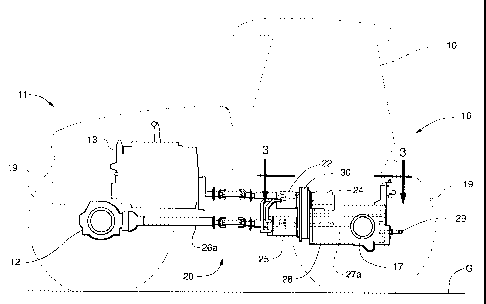
Fig. 3 is a top plan view of the splitter gearbox and rear axle housing
CA 02280247 1999-08-12
-5-
corresponding to lines 3--3 of Fig. 2;
Fig. 4 is a front elevational view of the splitter gearbox and associated
drives corresponding to lines 4--4 f Fig. 3;
Fig. 5 is a rear elevational view of the splitter gearbox corresponding to
lines 5--5 of Fig. 3;
Fig. 6 is a cross-sectional view through the splitter gearbox taken along
lines 6--6 of Fig. 3;
Fig. 7 is a cross-sectional view of the splitter gearbox taken along lines
7--7 of Fig. 6 to depict the gear drive system for driving the front and rear
axles
from a single hydrostatic motor shown in phantom;
Fig. 8 is a cross-sectional view of the splitter gearbox similar to that of
Fig. 6 to depict the addition of an optional auxiliary pump mechanism; and
Fig. 9 is a top plan view of the splitter gearbox and rear axle housing
similar to that of Fig. 3 but with an optional auxiliary hydraulic pump
mounted
to the splitter gearbox.
DETAILED DESCRIPTION OF THE PREFERRED EMBODIMENT
Referring now to Fig. 1, a four wheel drive, articulated tractor
incorporating the principles of the instant invention can best be seen. The
articulated tractor 10 includes a forward engine end 11 supported above the
ground G by a front axle assembly 12 and carrying an engine 13. The rearward
cab end 16 of the tractor 10 is supported above the ground by a rear axle
assembly 17 and has an operator's station 18 mounted thereon. Each of the
front and rear axle assemblies 12, 17 is provided with a pair of opposing
wheels
19 for mobile movement of the tractor 10 over the surface of the ground G.
The front and rear ends 11, 16 of the tractor 10 are connected by an
articulation
joint 15, the manipulation of which effects steering of the tractor 10 in a
known
manner.
CA 02280247 1999-08-12
-6-
As best seen in Figs. 1- 7, the tractor 10 is provided with a drive system
20 that is operatively connected to the engine 13 to provide operative power
for
the front and rear axle assemblies 12, 17. The drive system 20 includes a
splitter gearbox 30 mounted on the front of the rear axle assembly 17 in a
manner to share the oil sump therewith for lubrication purposes. The drive
system 20 also includes the input drive components, including a hydrostatic
pump 22 for powering the traction drive of the tractor 10, a hydraulic pump 24
for pressuring the hydraulic system of the tractor 10, and a power takeoff
(PTO) mechanism 29; and the output drive components, including a variable
displacement hydrostatic motor 25 to provide operative power to both the front
and rear axle assemblies 12, 17 through front and rear output drive shafts 26,
27.
The splitter gearbox 30 receives rotational power from the engine 13 via
a power input shaft 31 interconnecting the engine 13 and the splitter gearbox
30
to rotate the input gear 32. As best seen in Figs. 4 - 6, the input gear 32 is
drivingly engaged with a first idler drive gear 33, the size of the respective
gears 32, 33 being selected to provide the appropriately desired gear
reduction.
The first idler drive gear 33 is drivingly engaged with a pump drive gear 34
having both the hydrostatic pump 22 and the hydraulic pump 24 coaxially
mounted therewith, the hydrostatic pump 22 being mounted on the front of the
splitter gearbox 30 and the hydraulic pump 24 being mounted on the rear of the
splitter gearbox 30. The idler drive gear 33 is also drivingly engaged with
the
PTO drive gear 39 for powering the PTO mechanism 29 as a direct drive input
from the engine 13.
As best seen in Figs. 3 - 7, the hydrostatic pump 22 is operable to
circulate hydraulic fluid under pressure to a variable displacement hydraulic
motor 25 mounted on the front of the splitter gearbox 30 below the hydrostatic
pump 22 to drive rotation of the hydraulic motor 25. The drive pinion 35 of
the
CA 02280247 1999-08-12
-7-
hydrostatic motor 25 is drivingly engaged with a second idler gear 36, which
is
also appropriately sized to provide the desired gear reduction. The second
idler
gear 36 is drivingly engaged with a traction driven gear 37 having a single
shaft
38 extending therethrough to project both forwardly and rearwardly from the
splitter gearbox 30 and form the front and rear output drive shafts 26, 27.
Control of the hydrostatic pump is effected through a conventional mechanical
linkage.
The hydrostatic motor 25 is preferably set-up with three pre-set, fixed
swash plate angles to provide three positive displacements for the motor 25 to
proximate a conventional operation of the tractor 10. By utilizing the
variable
displacement of the hydrostatic motor 25 and/or a variable speed hydrostatic
pump 22, the infinite speed adjustment for the tractor 10 can still be
attained
on-the-go. Using an electronic control system to control the operation of the
motor 25, such as by modulating the displacement of the motor 25, and to
control the operation of the pump 22, a very smoothly operating power-shift
tractor 10 will result without requiring the operator to stop the tractor to
change
gears in a mechanical transmission, as is conventional. The fixed, pre-set
displacements for the hydrostatic motor 25 provide maximum torque and
minimum speed at a first position, a mid-range of both torque and speed at a
second position, and a minimum torque with maximum speed for roading
operations at a third position.
As best seen in Figs. 1 and 2, the front axle assembly 12 is drivingly
connected to the front output drive shaft 26 by a front drive shaft assembly
26a.
The rear axle assembly 17 is drivingly connected to the rear output drive
shaft
27 by a rear drive shaft assembly 27a passing internally through the housing
28
of the rear axle assembly 17. Likewise, the PTO mechanism 29 is drivingly
connected to the PTO drive gear 39 and passes through the housing 28 of the
rear axle assembly 17 and projects rearwardly therefrom for remote connection
CA 02280247 1999-08-12
-8-
to an apparatus (not shown) for delivering rotational power thereto.
Accordingly, the top portion of the splitter gearbox 30 receives
rotational power directly from the engine 13 and drives the input drive train
components, including the hydrostatic pump 22, the hydraulic pump 24 and the
PTO mechanism 29. The lower portion of the splitter gearbox 30 receives
operative power from the hydrostatic motor 25 operatively driven from the
hydrostatic pump 22 and delivers the rotational power through the output
shafts
26, 27 to drive the front and rear axle assemblies 12, 17 from a single
hydrostatic motor 25 off of a single gear drive set 35-37.
Referring now to Figs. 8 and 9, the configuration of the splitter gearbox
30 to receive an optional, auxiliary hydraulic assembly 40, which includes an
auxiliary pump 41, having a drive pinion 42, and a rotatably mounted third
idler
gear 43 drivingly engaged with the drive pinion 42. The third idler gear 43
projects outwardly from the housing 44 of the auxiliary hydraulic assembly 40
such that the mounting of the housing 44 to the side of the splitter gearbox
30,
as described in greater detail below, will cause the third idler gear 43 to
become
drivingly engaged with the input gear 32 and, thereby, drive the operation of
the auxiliary pump 41, which can then supplement to operation of the primary
hydraulic pump 24.
The process for installing the auxiliary hydraulic assembly 40 is best
seen in Fig. 8. First the removable side cover 45 of the splitter gearbox 30
is
detached from the splitter gearbox 30. The auxiliary hydraulic assembly 40 is
then positioned such that the third idler gear 43 extends into the opening in
the
side of the splitter gearbox 30 formed with the removal of the side cover 45
and
becomes engaged with the input gear 32 to receive rotational power directly
from the engine 13, as is the primary hydraulic pump 24. The housing 44 is
then bolted into place on the side of the splitter gearbox and sealed thereto
as a
replacement for the side cover 45.
CA 02280247 1999-08-12
-9-
The splitter gearbox configuration described above provides a number of
different operational configurations for the operator of this hydrstatically
driven
tractor 10. By disengaging all other output components, the operator can
choose to direct the entire power of the engine 13 to the hydrostatic motor 25
to
provide for maximum speed and/or pulling torque of the tractor 10 through one
of the pre-set fixed positions of the motor 25. Alternatively, the operator
could
disengage the hydrostatic motor 25 by placing its swash plate in a neutral
position and run the entire power of the engine 13 through the PTO shaft 29,
while the tractor 10 remains stationary. Another alternative for the operator,
would be to disengage both the hydrostatic motor 25 and the PTO mechanism
29, and run the entire power of the engine 13 through the auxiliary hydraulic
system 40. Yet another alternative for the operator would be to disengage all
of
the hydrostatic motor 25, the PTO mechanism 29, and the auxiliary hydraulic
system 40 (if the tractor 10 is so equipped), and divert as much of the power
from the engine as possible through the tractor hydraulic system through the
hydraulic pump 24; however, since both the hydrostatic pump 22 and the
hydraulic pump 24 are run from the same gear 34, less than full engine power
can be run through the tractor hydraulics. One skilled in the art will readily
recognize that a combination of the above systems will typically be operated,
and the operator will have appropriate choices to make for application of the
power from the engine 13.
It will be understood that changes in the details, materials, steps
and arrangements of parts which have been described and illustrated to explain
the nature of the invention will occur to and may be made by those skilled in
the art upon a reading of this disclosure within the principles and scope of
the
invention. The foregoing description illustrates the preferred embodiment of
the invention; however, concepts, as based upon the description, may be
employed in other embodiments without departing from the scope of the
CA 02280247 1999-08-12
-10-
invention. Accordingly, the following claims are intended to protect the
invention broadly as well as in the specific form shown.
10
20