Note: Descriptions are shown in the official language in which they were submitted.
.. CA 02280332 1999-08-13
INTERNAL FERRULE FOR PAINT BRUSH WITH
BRISTLE CLAMPING PANEL AND
REMOVABLE BRISTLE PACK
FIELD OF THE INVENTION
This invention pertains to a novel internal ferrule which is
used in a paint brush that has a removable bristle pack and one or more
moveable bristle clamping panels which, when in a closed position, grip
the bristle pack and prevent paint from migrating up the bristles to the
base of the paint brush handle. The paint brush with the internal ferrule
and the removable bristle pack is easy to use, and provides ready
cleaning after use, by releasing the one or more panels and enabling the
bristle pack to be removed and exposed to the cleaning solution.
BACKGROUND OF THE INVENTION
A longstanding problem with paint brushes that have fixed
bristles that are used for industrial and domestic painting applications is
that with time and repeated use, paint tends to build up within the bristles
of the brush in the region where the bristles are held by the ferrule clamp
that joins the bristles with the paint brush handle and base. The collected
paint in this confined area is difficult to clean away. Usually, some
residual paint is left in the bristles at the junction with the ferrule even
after the used brush has been cleaned. The dried paint at this location
collects and builds up over time with repeated use of the paint brush.
This causes the bristles of the brush to spread and thereby reduces the
efficiency of the brush. Also, the build up of dried paint tends to cause
CA 02280332 1999-08-13
-2-
the bristles to wear and break at the location of the dried paint. This
reduces the life of the paint brush.
Proper cleaning of a paint brush requires a considerable
amount of solvent, if the person cleaning the brush is meticulous. If the
paint has a water base, this is also a serious problem because large
amounts of water are wasted attempting to thoroughly clean the brush.
However, if the paint is an oil base paint, then expensive petroleum paint
solvent or thinner is required for cleaning. The use of a petroleum base
solvent constitutes a waste of costly solvent and at the same time creates
an environmental pollutant. Most commercial painters will tend to
minimize costs by balancing the amount of the solvent used with the
number of times the paint brush is used. It may be economic, for in-
stance, to only expect a paint brush to be used a half dozen times before
it must be discarded, rather than incur the cost and waste a considerable
amount of solvent attempting to meticulously clean the brush after each
use, and prolong the life of the paint brush.
A paint brush which minimizes or eliminates the build up of
paint in the location where the bristles are set or meet the paint brush
handle is desirable. Any invention which reduces the amount of solvent
which is required to clean a paint brush is useful. It is also beneficial if
a mechanism is used which reduces or eliminates bristle flare as it occurs
over time when a paint brush is repeatedly used.
U.S. Patent No. 5,289,606, March 1, 1994, Blake A.
Ledingham, discloses a unitary paint brush which comprises a paint brush
CA 02280332 1999-08-13
-3-
body attached to a handle. The body defines a cavity adapted for
receiving a group of bristles. A pair of hinged releasable flaps project
over the cavity to abut the bristles when moved to a closed position. The
bristles are released by moving the flaps into an open position. The
hinged flaps are held in place on the bristle pack base by springs which
can be rotated from a flap open position to a flap closed position, and
vice versa. A problem with the springs is that they are a separate
component from the body and raise manufacturing expense.
U.S. Patent No. 5,315,733, May 31, 1994, Blake A.
Ledingham, discloses a paint brush bristle clamp which can be removed
after paint brush use, and facilitates cleaning of paint from the brush.
The removable paint brush bristle clamp comprises: a pair of opposed
end walls; a first side wall located between the pair of end walls and
joined thereto; a second side wall opposed to the first side wall, the
second side wall being joined at one end to one of the end walls, the
opposite end of the second side wall being free and having a first lip
formed thereon; and a second lip formed on one end of one of the end
walls, adjacent to the lip formed on one edge of the adjacent side wall,
said second lip being adapted to mate with the first lip on the side wall
to thereby provide an opening and closing action.
U.S. Patent No. 5,435,037, July 25, 1995, Blake A.
Ledingham, discloses a paint brush with a replaceable bristle pack. The
unitary paint brush with replaceable bristles comprises: a paint brush
body and handle, the body having formed in one end thereof opposite the
handle a cavity adapted for receiving a group of bristles; at least one
CA 02280332 1999-08-13
-4-
releasable member secured to one side of the paint brush body, and
projecting over the cavity, the releasable member being capable of
abutting the bristles when moved to a first closed position, and being
removed from the bristles when moved to a second open position; at least
one movable securing member for securing the hinged releasable member
in a first position and releasing the hinged releasable member for
movement to a second open position; and a group of bristles held
together and located within the cavity of the holder, and held in place by
the hinged releasable member, said bristle group being removable and
secured in place by the releasable member.
U.S. Patent No. 4,129,918, December 19, 1978, Robert
Lee, discloses an adjustable sleeve for an artist's paint brush adapted to
adjust the effective length of the bristles of the brush. The adjustable
sleeve is tubular at its tip to contain the hair or bristles. The sleeve is
split above the tip to provide a spring biased grip upon the brush ferrule.
The adjustable sleeve is tapered in substantial conformity with the taper
of the ferrule and it is longitudinally adjustable relative to the ferrule to
vary the effective length of the hair or bristles. The sleeve is designed
for use with an artist's brush, which has bristles arranged in a taper
column form. The sleeve does not fit over the base of the brush at the
location where the bristles meet the base.
U.S. Patent No. 4,237,579, December 9, 1980, Jonathan H.
Salmon, discloses a tool for applying a liquid stain to a flat surface to
impart a timber grain effect to the surface. The tool comprises a paint
brush, a bristle retaining slidable plate on one side of the brush and a
CA 02280332 1999-08-13
- 5 -
slidable comb plate on the other side of the brush. Both of the plates
have an elongated slot which engages a bolt which passes through the
paint brush. The comb adjustably separates the brush bristles into
discrete bunches to permit the application of stain to impart a wood grain
pattern to the surface. This tool does not disclose a holder which fits on
both sides of the paint brush base where the bristles are secured to the
base. The tool is not designed to prevent paint from migrating down the
bristles in the direction of the base.
U.S. Patent No. 4,339,837, July 20, 1982, Christiaan
Reeberg, discloses a sliding box-like girdle which fits over a paint brush
to confine the bristles. The girdle acts as a hanger so that the paint brush
can be hung on a wall. The girdle also protects the brush bristles while
on display, or during storage. Further, the girdle is used to control the
effective length of the bristle ends for specific painting jobs. The girdle
also serves to squeeze excess paint from the bristles after each dip into
a can of paint. The girdle does not serve to encircle the base of the paint
brush, where the bristles meet the paint base, and thereby prevent paint
from migrating along the bristles to the base, and thereby collecting at
the base-bristle ended face.
French Patent No. 714,282, Deroubaix et al., published
November 10, 1931, discloses a paint brush with a removable bristle
pack, a hinged panel 5 which, in a closed position, grips the bristles 7,
and a ring 8 which encloses the bristles 7. The ring 8 can possibly be
interpreted as an internal ferrule. However, the ring 8 has no ridges that
fit within grooves inside the cavity. Also, Deroubaix et al. use a sliding
CA 02280332 1999-08-13
-6-
ring 9 which can be moved up once the panel 5 is closed in order to hold
the brush together (see Figure 4).
SUMMARY OF THE INVENTION
The invention is directed to an internal ferrule for use with
a paint brush handle and a removable bristle pack comprising: (a) a
hollow girdle for encircling a first end of a bundle of parallel bristles, the
girdle having interior and exterior faces; (b) a concave glue cavity
formed in an interior face of the hollow girdle; and (c) a protrusion
formed on an exterior face of the girdle for engaging with a releasable
securing member associated with the body of a paint brush handle.
The ferrule can have a hollow rectangular or oval shape.
The rectangular shaped ferrule can have a pair of protrusions formed in
opposite exterior face ends of the ferrule. A complementary pair of
protrusions can be formed on opposite exterior side faces of the
rectangular ferrule. Two opposing exterior faces of the internal ferrule
can have complementary quadrangle shapes.
The paint brush according to the invention can comprise: (a)
a paint brush body having a first end and a second end, and a first side
and a second side, and a handle connected to the first end of the body,
the body having formed in the second end thereof opposite the handle a
cavity for receiving one end of a group of bristles; (b) a group of bristles
held together and having a first end which is received in the cavity, and
a second free end which protrudes from the cavity; (c) a hollow girdle
CA 02280332 1999-08-13
for encircling the first end of the group of bristles; (d) a concave glue
cavity formed in an interior face of the hollow girdle; (e) a protrusion
formed on the exterior of the hollow girdle for removably engaging with
a releasable member associated with the paint brush body; and
(f) at least one hinged releasable member secured to the first side of the
paint brush body, and projecting over the cavity, the hinged releasable
member abutting and securing the girdle when moved to a first closed
position, and being spaced from and releasing the girdle when moved to
a second open position.
The paint brush can include a securing member for securing
the hinged releasable member in the first closed position and releasing the
hinged releasable member when in a second open position. The girdle
can be an internal ferrule that has a hollow rectangular shape. The
hollow rectangular shaped ferrule can have a pair of protrusions formed
in opposite exterior face ends of the ferrule. A complementary pair of
protrusions can be formed on opposite exterior side faces of the
rectangular ferrule. Two opposing exterior side faces of the internal
ferrule can have complementary quadrangle shapes.
The hinged releasable member can pivot in a manner
whereby the free end of the hinged releasable member, when in a closed
position, can abut and hold the external face of the girdle on the bristle
pack. The hinged releasable member can pivot in a manner whereby the
free end of the releasable member faces the handle of the paint brush and
the pivot axis for the releasable member is located laterally across the
body of the paint brush at the edge of the cavity. The cavity can include
CA 02280332 1999-08-13
two grooves for receiving the pair of protrusions formed on the exterior
faces of the internal ferrule.
DRAWINGS
In the drawings which represent detailed illustrations of
specific embodiments of the invention, but which should not be construed
as limiting the scope of the invention in any way:
Figure 1 illustrates a perspective view of a paint brush with
a replaceable bristle pack, and panel and clips holding the bristle pack in
place.
Figure 2 illustrates a perspective view of a second embodi-
ment of paint brush with replaceable bristle pack, and an inverted single
clamping panel.
Figure 3 illustrates a perspective view of an internal ferrule
for a paint brush with removable bristle pack, the ferrule having
horizontal ridges on both the front and rear faces (not visible) and
opposing end ridges.
Figure 4 illustrates a front view of a rectangular shaped
internal ferrule, to be used in association with a right angle edge paint
brush having either a pair of clamping panels, or a single clamping panel
as illustrated in Figures 12 and 13.
CA 02280332 1999-08-13
-9-
Figure 5 illustrates an end view of the internal ferrule
illustrated in Figure 4.
Figure 6 illustrates a quadrangle shaped internal ferrule for
use in association with the angled edge paint brush and replaceable bristle
pack illustrated in Figure 1.
Figure 7 illustrates an end view of the quadrangle shaped
internal ferrule illustrated in Figure 6.
Figure 8 illustrates a front view of an embodiment of internal
ferrule that has protruding front and rear ridges but not end ridges.
Figure 9 illustrates an end view of the embodiment of
internal ferrule illustrated in Figure 8.
Figure 10 illustrates an exploded perspective view of the
angle edge paint brush and replaceable bristle pack as illustrated in
Figure 1, with the clips moved away from the pivotable clamping panel,
the clamping panel in raised position, and the bristle pack and internal
quadrangular shaped ferrule as illustrated in Figures 6 and 7 removed
from the interior of the body of the paint brush handle.
Figure 11 illustrates an exploded perspective view of a paint
brush and replaceable bristle pack as illustrated in Figure 2, with the
inverted pivotable clamping panel in raised position and the bristle pack
with the embodiment of internal ferrule that is free of end ridges as
CA 02280332 2004-02-23
- 10-
illustrated in Figures 8 and 9 removed from the interior of the body of the
paint brush handle.
Figure 12 illustrates an end section view of an embodiment of
paint brush that has a single clamping panel and removable bristle pack and
an internal ferrule as illustrated in Figures 8 and 9 in position in the
interior of the body of a paint brush handle.
Figure 13 illustrates an end section view of the paint brush
with a single clamping panel and removable bristle pack, with internal
ferrule as illustrated in Figures 8 and 9, being removed from the interior
of the paint brush body handle, after the single clamping panel has been
pivoted away from a clamping position.
Figure 14 illustrates a front elevation view of a paint brush
handle, with replaceable bristle pack and internal ferrule as illustrated in
Figures 3, 4 and 5 in position in the interior of the paint brush handle, the
single clamping panel having been removed to expose the internal ferrule.
The internal ferrule has both horizontal front and rear face ridges and
opposing end ridges.
DETAILED DESCRIPTION OF
SPECIFIC EMBODIMENTS OF THE INVENTION
The technology relating to paint brushes with replaceable
bristle packs is disclosed in U.S. Patents Nos. 5,289,606 and 5,435,037.
A problem with the paint brush designs and the replaceable bristle packs
CA 02280332 2004-02-23
-11-
as disclosed in the foregoing U.S. patents is that in some instances, the
replaceable bristle pack is not held firmly in place in the interior cavity of
the paint brush handle and body, when the clamping panels) is (are)
moved to the normal closed clamping position. Sometimes, even when
clamped, due to bristle swell or improper position of the removable bristle
pack in the cavity, the removable bristle pack wiggles slightly when
pressure is applied to the bristles. This is unacceptable, especially for
professional painters who require a firm brush. There is therefore a need
for a mechanism which holds the removable bristle pack securely when it
is in position in the bristle receiving cavity in the interior of the paint
brush
handle and body.
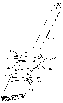
Referring to the drawings, Figure 1 illustrates a perspective
view of an angle edge paint brush with a replaceable bristle pack and
panel, and clips holding the bristle pack in place. As seen in Figure 1, the
paint brush handle 2 has a top hinged clamping panel 4 on the front face
of the body of the handle, a pair of closed pivotal clips 6 holding the
clamping panel 4 in position against the top end of the removable bristle
pack 8, the opposite free bristle end projecting from the interior of the
paint brush handle 2. A pair of slits 21 (only one is visible) are formed in
the ends of the sides of the handle 2, adjacent the bristle end. The slits 21
provide some "give" in the side ends of the handle 2. As an alternative
embodiment, the paint brush can have a second rear top hinged clamping
panel, which is held by the same pivotal clips 6.
Figure 2 illustrates a perspective view of a second embodi-
ment of paint brush with right angle edge, replaceable bristle pack, and
CA 02280332 1999-08-13
- 12-
a single inverted clamping panel. As seen in Figure 2, the single
inverted clamping panel 12 is formed in the body of the paint brush
handle 10 and pivots on pivot pin 14. When the inverted clamping panel
12 is clamped in position against the body of the paint brush handle 10
and the bristle pack 16 (as seen in Figure 2), the end of the bristle pack
16 with the internal ferrule (not visible) opposite the visible free end is
held securely in place in the interior bristle receiving cavity of the body
of the paint brush handle 10. The clamping panel 12 has a resilient
releasable clip projection 15, which catches under the top edge 17 of the
paint brush body and holds the panel 12 closed (see Figure 11). While
not shown in Figures 1 and 2, small slits can be cut in the ends of the
sides of the paint brush body, adjacent the cavity and the bristle pack 8
or 16. These slits provide a slight amount of "give" when the bristle
pack 8 or 16 is inserted in the cavity (see Figure 11).
Figure 3 illustrates a perspective view of a square edge
internal ferrule for the removable bristle pack held in the paint brush. As
seen in Figure 3, the internal ferrule 18 is constructed to have an
elongated hollow rectangular shape. On the front elongated face of the
internal ferrule 18, there is a long horizontal clamping ridge 20 formed
in the lower area of the front panel of the internal ferrule 18. A similar
elongated ridge is formed in the rear face of the internal ferrule 18,
although it is not visible in Figure 3. The internal ferrule 18 also has on
each end thereof a pair of opposite protruding horizontal end ridges 22.
The interior facing front and rear faces of the hollow internal ferrule 18
have formed therein respective glue cavities 24.
. CA 02280332 1999-08-13
-13-
The internal ferrule 18 as seen in Figure 3 fits about one end
of a removable pack of bristles as seen in Figures 12 and 13. The
internal ferrule 18 is held securely in place on the end of the bristle pack
8 by glue which is injected into the pair of glue cavities 24 once the
internal ferrule 18 has been put in position about one end of the parallel
set of bristles forming the bristle pack 8.
Figure 4 illustrates a front view of the square edge rectangu-
lar shaped embodiment of the internal ferrule 18 as seen in Figure 3.
This embodiment of internal ferrule is designed to be used in association
with the square edge paint brush illustrated in Figure 2, similar to the one
illustrated in Figure 1, but with a square edge instead of an angled edge.
This embodiment with clips 6 can comprise either one clamping panel 4,
or a pair of opposing clamping panels. Figure 5 illustrates an end view
of the internal ferrule illustrated in Figure 4.
Figure 6 illustrates a quadrangle shaped internal ferrule for
use in association with the angle edge paint brush and replaceable bristle
pack illustrated in Figure 1. As seen in Figure 6, the internal ferrule 18
has elongated horizontal front and rear face ridges 20 and opposite
protruding end ridges 22. Figure 7 illustrates an end view of the
quadrangle shaped internal ferrule illustrated in Figure 6. The clamping
panel 4 of the paint brush illustrated in Figure 1 has a quadrangular shape
to conform with the angled end of the bristles 8.
CA 02280332 1999-08-13
- 14-
Figure 8 illustrates a front view of an embodiment of internal
ferrule that has protruding front and rear ridges but not end ridges.
Figure 9 illustrates an end view of the embodiment of internal ferrule
illustrated in Figure 8.
Figure 10 illustrates an exploded perspective view of the
angle edge paint brush and replaceable bristle pack as illustrated in
Figure 1, with the pair of clips 6 moved away from the pivotable
clamping panel 4, the clamping panel in raised position, and the
removable bristle pack and internal quadrangle shaped ferrule removed
from the interior bristle receiving cavity of the body of the paint brush
handle 2. As seen in Figure 10, the pair of clips 6 have been moved
away from the clamping panel 4 and the body of the paint brush. The
clamping panel 4 has been moved to a raised position, and the bristle
pack 8, with the internal ferrule 18 glued in position on one end of the
parallel pack of bristles 8 has been withdrawn from the interior of the
paint brush handle 2. Figure 10 also illustrates how the two pivotal end
panels 30 can be pivoted outwardly to enable the bristle pack 8 and
internal ferrule 18 to be readily inserted and removed from the interior
cavity in the paint brush handle 2.
Figure 10 also illustrates one of a pair of internal grooves 26
which are formed in the interior of the cavity in the paint brush handle
2 at the top end of each of the two pivotal end panels 30. The pair of
internal grooves 26 are designed to conform with and receive the pair of
opposite protruding end ridges 22, which extend from each end of the
internal ferrule 18. The pair of elongated ridges 20 on the front and rear
CA 02280332 1999-08-13
-15-
faces of the internal ferrule 18 are used to provide a friction bearing face
which can be gripped securely by the interior face of the clamping panel
4 when it is moved to a lower clamping position and clipped by clips 6,
as illustrated in Figure 1.
Figure 11 illustrates an exploded perspective view of a paint
brush and replaceable bristle pack as illustrated in Figure 2, with the
inverted pivotable clamping panel 12 in raised position and the replace-
able bristle pack 16 with the internal ferrule 18 removed from the interior
cavity of the body of the paint brush handle 10. As seen in Figure 11,
the clamping panel 12 of the paint brush 10 has been pivoted to a raised
position. This permits the bristle pack 16 and the internal ferrule 18 to
be removed from the interior of the cavity formed in the body of the
paint brush handle 10. Unlike the design of internal ferrule illustrated in
Figure 10, in this embodiment of paint brush, there is no pair of
protruding end ridges 22 on the ferrule, or any corresponding internal
side grooves 26 formed in the interior of the ends of the cavity of the
paint brush handle 10. Since the panel 12 pivots on pins 14 close to the
bristle end of the brush 10, the end faces cannot be pivoted away to
receive the bristle pack. Thus the ferrule 1$ must be of the design shown
in Figures 8 and 9 with no end ridges which will interfere with entry of
the bristle pack and ferrule 18 into and out of the cavity. The internal
ferrule 18 still has, however, the horizontal ridges 20 which enable the
panel 12 and the opposite brush side to bear against the internal ferrule
18 and grip it securely. The panel 12 has a resilient release clip 15
which assists in holding panel 12 in a closed position by catching on the
edge 17 of the paint brush body 10. The ends of the body of the holder,
CA 02280332 1999-08-13
- 16-
adjacent the cavity opening, also have a pair of end slits 21 which can
spread and assist insertion of the ferrule 18 into the cavity.
Figure 12 illustrates an end section view of an embodiment
of removable bristle pack and internal ferrule in position in the interior
of the body of a paint brush handle having a single clamping panel 4. As
seen in Figure 12, the bristle pack 8 with the internal ferrule 18 at the
top portion thereof is held securely in place by single clamping panel 4
which is in a closed position abutting on horizontal ridge 20 of the
internal ferrule 18. The pair of complementary glue cavities 24, which
contain glue and thereby cement the internal ferrule 18 to either side of
the top portion of the bristle pack 8, are clearly visible in Figure 12.
Figure 12 also illustrates a standard bristle separator 28, which is
typically present in the top portion of the interior of the bristle pack 8.
The purpose of the bristle separator 28 is to prevent the opposite free
ends of the bristles 8 from spreading and thereby detracting from the
usefulness of the paint brush. The free end of panel 4 also clamps
against bristles 8 and holds the group of bristles together. Figure 12 also
illustrates gap 32 which serves to hold paint and thereby enables the
brush to be used longer, before having to dip the brush in the paint pot
for a fresh loading.
Figure 13 illustrates an end section view of the removable
bristle pack, with single clamping panel and internal ferrule, being
removed from the interior of the paint brush body handle, after the
clamping panel 4 has been pivoted away from a clamping position. As
seen in Figure 13, the clamping panel 4 by being pivoted away from the
CA 02280332 1999-08-13
- 17 -
closed position, releases the bristle pack 8 and the internal ferrule 18 so
they can be withdrawn. When the clamping panel 4 is in the open
position, the bristle pack 8 and the internal ferrule 18 can be either
readily removed from or re-inserted into the interior of the paint brush
handle and body 2. The painted and coated bristle packs can be removed
for cleaning and reused, or the old bristle pack can be replaced with a
new bristle pack. While not visible in Figures 12 and 13, the end panels
30 (see Figure 10) also pivot away to release the bristle pack 8.
Figure 14 illustrates a front elevation view of a paint brush
handle, similar to the one shown in Figures 12 and 13, with replaceable
bristle pack and internal ferrule as illustrated in Figures 3, 4 and 5, in
position in the interior cavity of the paint brush handle, the clamping
panel having been removed to expose the internal ferrule. As seen in
Figure 14, with the clamping panel 4 removed, the internal ferrule 18 at
the top region of the bristle pack 8 fits within the interior cavity of the
paint brush handle and body 2. The horizontal elongated ridge 20
extends across the bottom region of the internal ferrule 18. The
complementary pair of protruding end ridges 22 extend into and fit within
a matching pair of internal grooves 26 formed at the top internal ends of
the two pivotal end panels 30 of the paint brush handle and body 2. The
length of the internal ferrule 18 should be sufficiently long that at its
lower end, it hides the glue line on the bristles 8. The uneven glue line
can be unsightly, whereas the lower end of the ferrule 18 is neat and
clean.
. CA 02280332 1999-08-13
-18-
The paint brush handle and body 2 are typically formed of
extruded plastic and accordingly the two end pieces 30 have a slight
amount of flexibility. This enables the pair of protruding end ridges 22
of the ferrule 18 to snap into and be held in place in the complementary
pair of internal grooves 26 formed in the two end panels 30 of the paint
brush handle 2. In this way, the bristle pack is securely fixed in the
cavity of the paint brush when the clamping panel 4 is closed. The
internal ferrule 18 is formed of relatively rigid polymer material so that
end ridges 22 hold securely in the cavity.
The embodiments of internal ferrules and paint brushes
illustrated and discussed in this application can be produced on automated
assembly lines. It will be understood that various indentations and ridges
may be formed in the products in order to facilitate handling by the
automated assembly line.
Example
The paint brush must be formed of an appropriate polymer
so that it comprises a blend of stiffness (a flexible brush would be too
floppy when used) and resilience so that the brush, and particularly the
pivot panels, stand up to abuse, such as occurs when the brush is
inadvertently dropped. Tests with various polymers have been conducted
and the following table and calculations, demonstrate the manner in
which an appropriate blend of polymers for the paint brush was reached.
Through trial and error, it was concluded that a blend of 25 % #3434
CA 02280332 1999-08-13
- 19-
ACCTUF polypropylene and 75 % #9346 provides an acceptable paint
brush.
NEW RESIN BLEND
ORIGINAL RESIN - #9346 (REDS
TRIAL RESIN (handle only) ACCTUF #3434 YELLOW)
SPECS. IZOD. FLEX MOD. HEAT
#9346 .4 320 260
ACCTUF #3434 3 . 8 200 225
20% #3434 - Blend
80 % #9346 Approx. > 1.08 296 253
% #3434 - Blend
75 % #9346 Approx. > 1.25 290 251
CALCULATIONS
IZOD. FLEX MOD. HEAT
3.8 320 260
0-44 200 225
- 3.4 Difference - 120 Difference - 35 Difference
20 % of 3 .4 20 % of 120 20 % of 35
- .68 - - 24 - - 7.00
+ .40 320 260.00
- 1.08 - 296 - 253.00
25 % of 3 .4 25 % of 120 25 % of 35
- .85 - - 30 - - 8.75
+ .40 320 260.00
- 1.25 - 290 - 251.00
CA 02280332 1999-08-13
-20-
As will be apparent to those skilled in the art in the light of
the foregoing disclosure, many alterations and modifications are possible
in the practice of this invention without departing from the spirit or scope
thereof. Accordingly, the scope of the invention is to be construed in
accordance with the substance defined by the following claims.