Language selection

Search

Patent 2280506 Summary

Third-party information liability

Some of the information on this Web page has been provided by external sources. The Government of Canada is not responsible for the accuracy, reliability or currency of the information supplied by external sources. Users wishing to rely upon this information should consult directly with the source of the information. Content provided by external sources is not subject to official languages, privacy and accessibility requirements.

Claims and Abstract availability

Any discrepancies in the text and image of the Claims and Abstract are due to differing posting times. Text of the Claims and Abstract are posted:

  • At the time the application is open to public inspection;
  • At the time of issue of the patent (grant).
(12) Patent: (11) CA 2280506
(54) English Title: NON-STRUCTURAL STEEL STUDS
(54) French Title: POTEAUX D'ACIER NON PORTEURS
Status: Term Expired - Post Grant Beyond Limit
Bibliographic Data
(51) International Patent Classification (IPC):
  • E04C 03/32 (2006.01)
  • E04B 02/76 (2006.01)
  • E04C 03/04 (2006.01)
  • E04C 03/07 (2006.01)
(72) Inventors :
  • RICE, JOHN (Canada)
(73) Owners :
  • BAILEY METAL PRODUCTS LIMITED
(71) Applicants :
  • BAILEY METAL PRODUCTS LIMITED (Canada)
(74) Agent: DENNISON ASSOCIATES
(74) Associate agent:
(45) Issued: 2005-11-01
(22) Filed Date: 1999-08-19
(41) Open to Public Inspection: 2001-02-19
Examination requested: 2002-06-25
Availability of licence: N/A
Dedicated to the Public: N/A
(25) Language of filing: English

Patent Cooperation Treaty (PCT): No

(30) Application Priority Data: None

Abstracts

English Abstract

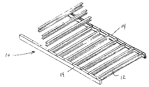
The present invention is directed to a nonload bearing partition wall including spaced apart wood top and bottom plates and a plurality of metal studs bridging the top and bottom plates. The metal studs have U-shaped rectangular cross section with two parallel spaced apart side walls and a central web bridging the side walls and connected to one edge of each of the side walls. The central web has an extension on each end thereof, the extension having a depth no greater than half the width of the sidewall. The extensions are contained within the slots of the top and bottom plates. One of the sidewalls has a first extension extending from either end over and attached to the edge of the top and bottom plates. The second side wall has second extensions extending from either end perpendicularly inwardly from the side wall to lie over and be attached to the inner face of the top and bottom plates.


French Abstract

La présente invention concerne une cloison de mur autoporteur comprenant des plaques de bois supérieure et inférieure espacées l'une de l'autre et une pluralité de poteaux métalliques reliant les plaques supérieure et inférieure. Les poteaux métalliques sont munis d'une section rectangulaire en forme de U avec deux parois latérales parallèles espacées et une zone centrale reliant les parois latérales et connectée à un rebord de chacune des parois latérales. La zone centrale possède une extension à chacune de ses extrémités, l'extension ayant une profondeur n'excédant pas la moitié de la largeur de la paroi latérale. Les extensions sont contenues dans les fentes des plaques supérieure et inférieure. Une des parois latérales est dotée d'une première extension, qui s'étend de chaque extrémité au-dessus et fixée au rebord des plaques supérieure et inférieure. La deuxième paroi latérale a une deuxième extension s'étendant de part et d'autre des extrémités perpendiculairement vers l'intérieur de la paroi latérale pour passer au-dessus et être attachée à la face interne des plaques supérieure et inférieure.

Claims

Note: Claims are shown in the official language in which they were submitted.


The embodiments of the invention in which an exclusive property or privilege
is
claimed are as follows:
1. A nonload bearing partition wall comprising spaced apart wood top and
bottom
plates having an inner face and opposing edges and a plurality of metal studs
bridging the top and bottom plates, the metal studs having a U-shaped
rectangular
cross section with two parallel spaced apart sidewalls and a central web
bridging the
sidewalls and connected to one edge of each of the sidewalls, the central web
having
an extension on each end thereof, the extension contained within slots
provided in
the inner surface of the top and bottom plates, one of the sidewalls having
first
extensions extending from either end of the sidewalls over an edge of the top
and
bottom plates and attached thereto, the second sidewall having second
extensions
extending from either end perpendicularly inwardly from the sidewall to lie
over
and be attached to the inner face of the top and bottom plates.
2. A nonload bearing partition wall according to claim 1 wherein the slots of
the top
and bottom plates have a depth less than one half the height of the edge of
the top
and bottom plates.
3. A nonload bearing partition wall according to claim 2 wherein the slots of
the top
and bottom plates are spaced 16 inches apart.

Description

Note: Descriptions are shown in the official language in which they were submitted.


CA 02280506 1999-08-19
JJ-10 099CA
TITLE: NON-STRUCTURAL STEEL STUDS
FIELD OF THE INVENTION
The present invention relates to a metal stud for use in a
partition wall having wood plates and the metal studs. The
invention also relates to a non-load bearing partition wall
constructed of wood plates and the metal studs
BACKGROUND OF THE INVENTION
It is the common practice in residential and much
commercial buildings to separate the various rooms by
partition walls to define the spaces of the building. Such
partition walls are generally nonload bearing and have in
the past been constructed of wood members including top and
bottom plates and bridging studs. The use of wood members
has its shortcomings. The supply of lumber is getting
scarcer and the cost has increased during recent years. In
addition wood can warp and go out of shape when it becomes
wet as well as beings acceptable to attack by vermin of
various kinds.
In recent years partition walls framed with sheet metal
members have been employed. The use of sheet metal members
provides advantages of dimensional stability, ease of
manufacture, and conservation of natural resources among
others. However the use of sheet metal framing members has
not gained widespread acceptance for various reasons. Load
bearing walls constructed of sheet metal members are not
generally less expensive than comparable walls framed with
wood members. In addition the use of metal framing members
requires specialized fastening systems other than the nails
which are typically utilized with wood members. V~hile this
does not generally present a problem during the framing of
the structure the finish carpentry including attaching of
trim materials is a problem as there is no proper
supporting surface for nailing of the trim member.
- 1 -

CA 02280506 1999-08-19
JJ-10 099CA
There have been attempts to overcome, the above
disadvantages by utilizing a composite wall having wood top
and bottom plates and sheet metal studs bridging the top
and bottom plates. Examples of such prior art structures
are given in United States Patents 4,001,993, 5,440,848,
and 5,596,859.
U.S. patent 4,001,993 to Daniels describes a sheet metal
stud having a shape and dimension corresponding
substantially to wood studs and a cross-sectional
configuration providing for rigidity and dimensional
stability. The metal studs are utilized with wood top and
bottom plates to which a sheet of particleboard has been
attached to the inner surface. The ends of the stud
penetrate the particleboard to protect the surface of the
wood plates. The studs are provided with extensions on
either side for nailing of the stud to the plates. However
the metal stud is expensive to manufacture and it is not
easy for the framers to construct partition walls utilizing
the metal stud as extensions on both sides must lie over
the edges of the top and bottom plates.
U.S. patent 5,440,848 describes metal studs to replace
vertical wood studs for use of framing of walls or
partitions. The ends of the metal studs are provided with
a flange on both ends of only one side of the metal stud to
lie over one edge of the top and bottom plate and a flange
on the web to lie over the inner surface of the top and
bottom plate. V~hile the stud is simple to install in
partition walls it does not have great dimensional
stability even when attached to the plates.
U.S. patent 5,596,859 describes a metal wall stud having
pre-punched nail or screw holes and pre-punched passageways
for electrical or plumbing facilities. The metal stud is
provided with integral tabs extending beyond the ends of
the stud walls which are foldable to provide connections to
- 2 -

CA 02280506 1999-08-19
JJ-10 099CA
wood plates or metal wall stud purlins in the construction
framing. The web of the stud is provided with split tabs
to provide lateral stabilization, greater
uplift loads, and the capability of being load bearing.
There still remains a need for a metal wall stud which
usable with wood top and bottom plates to provide for an
inexpensive and easy to assemble nonload bearing partition
wall.
SUMMARY OF THE INVENTION
The present invention is directed to a nonload bearing
partition wall comprising spaced apart wood top and bottom
plates and a plurality of metal studs bridging the top and
bottom plates. The metal studs have U-shaped rectangular
cross section with two parallel spaced apart side walls and
a central web bridging the side walls and connected to one
edge of each of the side walls. The central web has an
extension on each end thereof, the extension having a depth
no greater than half the width of the sidewall. The
extensions are contained within the slots of the top and
bottom plates. One of the sidewalls has a first extension
extending from either end over and attached to the edge of
the top and bottom plates. The second side wall has second
extensions extending from either end perpendicularly
inwardly from the side wall to lie over and be attached to
the inner face of the top and bottom plates.
BRIEF DESCRIPTION OF THE DRAWINGS
Preferred embodiments of the present invention are
illustrated in the attached drawings in which
Figure 1 is a perspective view of a wall according to the
present invention in the process of being constructed;
- 3 -

CA 02280506 1999-08-19
JJ-10 099CA
Figure 2 is a perspective view of the wall of figure 1 in
the process of being installed;
Figure 3 is a perspective view of the stud being inserted
into the slot of the plate;
Figure 4 is a perspective view of the first extension of
the stud being attached to the plate;
Figure 5 is a perspective view of the second extension of
the stud being attached to the plate; and
Figure 6 as a perspective view of the stud being attached
to the plate away from a slot.
DETAILED DESCRIPTION OF THE PREFERRED EMBODIMENTS
The present invention is directed to a nonload bearing
partition wall 10 constructed utilizing metal studs 12 and
wood top and bottom plates 14 as well as to the metal stud
12 utilized in the partition wall 10. The partition wall
10 has wood top and bottom plates 14 that are bridged by
the parallel spaced apart metal studs 12. The spacing
between the metal studs 12 is that typically utilized in
construction of partition walls generally at 16 inches on
center although other spacing such as 24 inches on center
may be utilized. To aid in the location of the studs 12
the top and bottom plates 14 are provided with slots 18 cut
into and across the inner surface of the top and bottom
plates 14. The slots 18 are spaced apart 16 inches to
provide for the proper spacing of the metal studs 12. The
slots have a depth less than 1/2 the depth of the top or
bottom plates 14.
The metal stud 12 has a generally U-shaped rectangular
cross section with two parallel spaced apart side walls 20
and a central web 22 bridging the side walls 20 and
connected to one edge of each of the side walls 20. The
- 4 -

CA 02280506 1999-08-19
JJ-10 099CA
central web 22 is provided with an extension 24 at either
end thereof, the extension 24 being capable of fitting
within the slot 18 of the top and bottom plate 14. One of
the side walls 20 is provided with a first extension 26 at
either end thereof and the second side wall 20 is provided
with a second extension 28 at either end thereof. The
extensions 24, 26, and 28 are formed from the end of the
stud by removing material to form the three extending
tongues 24, 26 and 28. The material of the stud forming
the extending lips on the sidewalls as well as a material
in the bend line between the sidewalls and the central web
is removed. This provides the extensions 24, 26 and 28 as
planar extending tongues extending from the ends of the
sidewalls 20 and central web 22. In order to make the
bending of the extensions 24, 26 or 28 easier slots 30 and
32 are cut into the extensions 24, 26 and 28 along the bend
lines.
Figures 3 to 5 illustrate the process of attaching the
metal studs 12 to the top and bottom plates 14 to form the
nonload bearing partition wall 10. The top and bottom
plates 14 are laid on edge spaced apart the height of the
partition wall 10 with their innerfaces containing the
slots 18 facing one another. The first extensions 26 on
the sidewalls 20 at either end of the stud 12 are bent
inwardly perpendicular to the sidewall 20. The stud 12 is
then placed into its bridging position between the top and
bottom plates 14 by sliding the extension 24 into the slot
18 until the second extension 28 of the side wall 20 rest
against the edges of the top and bottom plates 14. The
first extensions 28 rest against the inner face of the top
or bottom plates 14 and the web extension 24 is contained
within the slot 18. The studs 12 are then attached to the
top and bottom plates 14 by nailing through the first and
second extensions 26 and 28 into the top and bottom plates
14. The other studs 12 are installed in a similar manner
to form the completed nonload bearing partition wall 10.
Once the wall 10 is constructed it is lifted off the floor
- 5 -

CA 02280506 1999-08-19
JJ-10 099CA
into position and attached in the typical manner by nailing
through the top and bottom plates 14.
There may be situations where it is necessary to install a
stud 12 in a location where there is no precut slot 18.
The situations would typically arise where a stud is
required to support a fixture which would be attached to
the wall. In this situation the installer would have to
options. The first option would be for them to manually
cut slots in the top and bottom plate in the position in
which the stud is to be installed. Once the slots have
been cut the stud 12 would be installed in the usual manner
as described above. The second option as illustrated in
figure 6 would be to bend the web extension 24
perpendicularly outwardly from the web and then the first
extension 26 perpendicularly in the manner described above.
V~hen the stud 12 is placed between the top and bottom
plates 14 both the first extension 26 and the web extension
24 lie against the inner surface of the top and bottom
plate 14 while the second extension 28 lies against the
edge of the top or bottom plate 14. The stud is attached
to the top and bottom plates 14 by nailing through the
first extension 26 and second extension 28 in the manner
described above as well as through the web extension 24
into the top and bottom plate.
As finish carpenters prefer to be able to install wood trim
by nailing into a wood supporting structure it is preferred
if openings such as doors or windows which will be trimmed
by the finish carpenter be framed in the wall utilizing
wood studs.
The partition wall of the present invention as well as the
studs utilized in constructing the partition wall result in
a partition wall which is easier to produce for the framers
onsite than traditional all wood partition walls. As the
metal studs do not warp or bend is not necessary for the
framers to check the studs prior to their being utilized in
- 6 -

CA 02280506 1999-08-19
JJ-10 099CA
the partition wall. In addition as the top and bottom
plates are preferably provided with the slots, precut the
spacing of the studs in the partition walls are
predetermined, so it is not necessary for the framer to lay
out the stud spacing on the top and bottom plate prior to
the construction of the wall. Rather the framer merely has
to space apart the top and bottom plates, bend the
extensions on the studs, and drop the studs into place.
Once the studs are in place the studs are attached to the
plate preferably using an air hammer rare state or in the
wall lifted top and placed into position. To further speed
up the process, the studs may be supplied with the first
extensions pre-bent.
The metal studs of the present invention also help to
reduce other costs associated with construction. Due to
the U-shaping of the stud, the studs may be nested for
shipping, reducing the shipping volume by half compared to
an equivalent number of woods. Additionally, the metal
stud weighs less than wood studs, thus reducing the total
weight required for shipping.

Representative Drawing
A single figure which represents the drawing illustrating the invention.
Administrative Status

2024-08-01:As part of the Next Generation Patents (NGP) transition, the Canadian Patents Database (CPD) now contains a more detailed Event History, which replicates the Event Log of our new back-office solution.

Please note that "Inactive:" events refers to events no longer in use in our new back-office solution.

For a clearer understanding of the status of the application/patent presented on this page, the site Disclaimer , as well as the definitions for Patent , Event History , Maintenance Fee  and Payment History  should be consulted.

Event History

Description Date
Inactive: Expired (new Act pat) 2019-08-19
Letter Sent 2019-02-28
Inactive: Multiple transfers 2019-02-14
Inactive: Office letter 2007-01-31
Inactive: Corrective payment - s.78.6 Act 2007-01-22
Inactive: IPC from MCD 2006-03-12
Grant by Issuance 2005-11-01
Inactive: Cover page published 2005-10-31
Pre-grant 2005-08-19
Inactive: Final fee received 2005-08-19
Notice of Allowance is Issued 2005-07-06
Letter Sent 2005-07-06
Notice of Allowance is Issued 2005-07-06
Inactive: Approved for allowance (AFA) 2005-06-23
Amendment Received - Voluntary Amendment 2005-02-15
Inactive: S.30(2) Rules - Examiner requisition 2004-09-22
Letter Sent 2002-08-08
Inactive: Entity size changed 2002-07-10
Request for Examination Received 2002-06-25
Request for Examination Requirements Determined Compliant 2002-06-25
All Requirements for Examination Determined Compliant 2002-06-25
Application Published (Open to Public Inspection) 2001-02-19
Inactive: Cover page published 2001-02-18
Letter Sent 2000-09-12
Inactive: Single transfer 2000-08-17
Inactive: First IPC assigned 1999-10-08
Inactive: Courtesy letter - Evidence 1999-09-21
Inactive: Filing certificate - No RFE (English) 1999-09-16
Application Received - Regular National 1999-09-15

Abandonment History

There is no abandonment history.

Maintenance Fee

The last payment was received on 2005-06-20

Note : If the full payment has not been received on or before the date indicated, a further fee may be required which may be one of the following

  • the reinstatement fee;
  • the late payment fee; or
  • additional fee to reverse deemed expiry.

Patent fees are adjusted on the 1st of January every year. The amounts above are the current amounts if received by December 31 of the current year.
Please refer to the CIPO Patent Fees web page to see all current fee amounts.

Owners on Record

Note: Records showing the ownership history in alphabetical order.

Current Owners on Record
BAILEY METAL PRODUCTS LIMITED
Past Owners on Record
JOHN RICE
Past Owners that do not appear in the "Owners on Record" listing will appear in other documentation within the application.
Documents

To view selected files, please enter reCAPTCHA code :


To view images, click a link in the Document Description column. To download the documents, select one or more checkboxes in the first column and then click the "Download Selected in PDF format (Zip Archive)" or the "Download Selected as Single PDF" button.

List of published and non-published patent-specific documents on the CPD .

If you have any difficulty accessing content, you can call the Client Service Centre at 1-866-997-1936 or send them an e-mail at CIPO Client Service Centre.


Document
Description 
Date
(yyyy-mm-dd) 
Number of pages   Size of Image (KB) 
Representative drawing 2001-02-06 1 25
Abstract 1999-08-18 1 26
Description 1999-08-18 7 315
Claims 1999-08-18 1 28
Drawings 1999-08-18 3 90
Claims 2005-02-14 1 32
Representative drawing 2005-10-06 1 28
Filing Certificate (English) 1999-09-15 1 175
Request for evidence or missing transfer 2000-08-21 1 110
Courtesy - Certificate of registration (related document(s)) 2000-09-11 1 120
Reminder of maintenance fee due 2001-04-22 1 111
Acknowledgement of Request for Examination 2002-08-07 1 193
Commissioner's Notice - Application Found Allowable 2005-07-05 1 160
Courtesy - Certificate of registration (related document(s)) 2019-02-27 1 106
Correspondence 1999-09-15 1 14
Correspondence 2005-08-18 1 34
Correspondence 2007-01-30 1 14