Language selection

Search

Patent 2281324 Summary

Third-party information liability

Some of the information on this Web page has been provided by external sources. The Government of Canada is not responsible for the accuracy, reliability or currency of the information supplied by external sources. Users wishing to rely upon this information should consult directly with the source of the information. Content provided by external sources is not subject to official languages, privacy and accessibility requirements.

Claims and Abstract availability

Any discrepancies in the text and image of the Claims and Abstract are due to differing posting times. Text of the Claims and Abstract are posted:

  • At the time the application is open to public inspection;
  • At the time of issue of the patent (grant).
(12) Patent: (11) CA 2281324
(54) English Title: COMPOSITE TOOL HANDLE
(54) French Title: MANCHE D'OUTIL COMPOSITE
Status: Expired and beyond the Period of Reversal
Bibliographic Data
(51) International Patent Classification (IPC):
  • B25G 1/10 (2006.01)
  • B25B 7/00 (2006.01)
  • B25B 13/04 (2006.01)
  • B25B 13/14 (2006.01)
  • B25B 23/16 (2006.01)
  • B25G 1/12 (2006.01)
(72) Inventors :
  • LIN WU, LI-TU (Taiwan, Province of China)
(73) Owners :
  • LI-TU LIN WU
(71) Applicants :
  • LI-TU LIN WU (Taiwan, Province of China)
(74) Agent: BULL, HOUSSER & TUPPER LLP
(74) Associate agent:
(45) Issued: 2003-11-04
(22) Filed Date: 1999-09-03
(41) Open to Public Inspection: 2001-03-03
Examination requested: 1999-09-03
Availability of licence: N/A
Dedicated to the Public: N/A
(25) Language of filing: English

Patent Cooperation Treaty (PCT): No

(30) Application Priority Data: None

Abstracts

English Abstract


A composite tool handle includes a first body (14) made of steel alloy,
a second body (12) made of carbon fiber or glass fiber coated on the outer
periphery of the first body, and a third body (16) made of carbon fiber or
glass
fiber coated on the periphery of the second body.


Claims

Note: Claims are shown in the official language in which they were submitted.

6
THE EMBODIMENT OF THE INVENTION IN WHICH AN EXCLUSIVE
PROPERTY OR PRIVILEGE IS CLAIMED ARE DEFINED AS FOLLOWS:
1. A composite tool handle comprising:
a first body (14) having an outer periphery; and
a second body (12) attached to said outer periphery of said first
body (14).
wherein said second body (12) has a periphery, and said
composite tool handle further comprises a third body (16) coated on the
periphery of said second body (12); and
said third body (16) is made of carbon fiber.
2. The composite tool handle in accordance with claim 1, wherein
said first body (14) is made of steel alloy.
3. The composite tool handle in accordance with claim 1, wherein
said second body (12) is made of carbon fiber.
4. The composite tool handle in accordance with claim 1, wherein
said second body (12) is made of glass fiber.

Description

Note: Descriptions are shown in the official language in which they were submitted.


CA 02281324 2003-03-31
2
1 COMPOSITE TOOL HANDLE
2 The present invention relates to a composite tool handle.
3 A conventional tool handle in accordance with the prior art is made
4 of a steel alloy that is heavy, thereby causing inconvenience to a user when
rotating the tool handle to adjust a workpiece. In addition, the conventional
tool handle is electrically conductive such that the user is easily
susceptible to
7 shock when the workpiece contacts an electrical source, thereby injuring the
8 user or damaging the work piece. Further, the conventional tool handle with
9 little elasticity easily produces vibration when the user holds the tool
handle to
to rotate it to adjust the workpiece, thereby decreasing the stability of the
tool
11 handle. The present invention has arisen to mitigate and/or obviate the
12 disadvantages of the conventional tool handle.
13 In accordance with one aspect of the present invention, a composite
14 tool handle comprises a first body made of steel alloy having an outer
periphery, and a second body made of carbon fiber or glass fiber attached to
the
16 outer periphery of the first body.
17 The composite tool handle further comprises a third body made of
18 carbon fiber or glass fiber coated on the periphery of the second body.
19 Further benefits and advantages of the present invention will become
2o apparent after a careful reading of the detailed description with
appropriate
21 reference to the accompanying drawings.
22 In the drawings:
23 Fig. 1 is a side plan view in partial section of a composite tool handle
24 in accordance with the present invention;

CA 02281324 2003-03-31
3
1 Fig. 2 is a partial perspective view in partial section of the composite
2 tool handle in Fig. 1;
3 Fig. 3 is a side plan view in partial section of a composite tool handle
4 in accordance with another embodiment of the present invention;
Fig. 4 is a side plan view in partial section of a composite tool handle
6 in accordance with a further embodiment of the present invention;
7 Fig. 5 is a partial perspective view in partial section of the composite
8 tool handle in Fig. 4;
9 Fig. 6 is a top plan view in partial section of a composite tool handle
in accordance with a further embodiment of the present invention;
11 Fig. 7 is a partial perspective view in partial section of the composite
12 tool handle in Fig. 6;
13 Fig. 8 is a top plan view in partial section of a composite tool handle
14 in accordance with a further embodiment of the present invention;
Fig. 9 is a side plan view in partial section of a composite tool handle
16 in accordance with a further embodiment of the present invention; and
17 Fig. 10 is a partial side plan view in partial section of a composite
18 tool handle in accordance with a further embodiment of the present
invention.
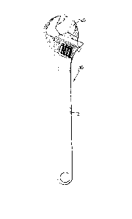
19 Referring to the drawings and initially to Figs. 1 and 2, a composite
2o tool handle in accordance with the present invention is adapted to suit an
21 adjustable wrench ( 10), and comprises a first body ( 14) made of steel
alloy, and
22 a second body ( 12) made of carbon fiber or glass fiber attached to the
outer
23 periphery of the first body ( 14). The first body ( 14) is formed with two
j aws
24 (140) in opposition to each other to adjust a workpiece (not shown).

CA 02281324 1999-09-03
4
1 In such a manner, the second body ( I 2) made of carbon fiber that is
2 light greatly decreases the weight of the composite tool handle, thereby
3 decreasing the cost of fabrication, and thereby facilitating a user
operating the
4 composite tool handle. In addition, the second body ( 12) made of carbon
fiber
with great strength and rigidity can efficiently increase the vibration
absorbing
6 effect of the tool handle when the user holds the tool handle to rotate it
to adjust
7 the workpiece, thereby increasing the stability of the tool handle. Further,
the
8 composite tool handle with the second body ( 12) has a great corrosion
resistant
9 and acid resistant capacity.
Alternatively, the second body ( 12) made of glass fiber can be used
11 to increase the aesthetic quality of the tool handle.
12 Further, the second body ( 12) made of carbon fiber or glass fiber will
13 prevent a user from being shocked by an electric current due to its
insulating
14 property, thereby assuring the user's safety when holding the tool handle.
Referring to Fig. 3, in accordance with another embodiment of the
16 present invention, the first body ( 14) longitudinally extends into the
middle of
17 the second body ( I 2).
18 Referring to Figs. 4 and 5, in accordance with a further embodiment
19 of the present invention, the composite tool handle is adapted to suit a
pair of
pliers ( 1 OA).
21 Referring to Figs. 6 and 7, in accordance with a further embodiment
22 of the present invention, the composite tool handle is adapted to suit a
closed
23 end wrench ( 1 OB).

CA 02281324 1999-09-03
1 Referring to Fig. 8, in accordance with a further embodiment of the
2 present invention, the composite tool handle further comprises a third body
( 16)
3 made of carbon fiber or glass fiber coated on the periphery of the second
body
4 ( 12).
5 Referring to Fig. 9, in accordance with a further embodiment of the
6 present invention, the composite tool handle is adapted to suit a pair of
side
7 cutting pliers ( 1 OC).
8 Referring to Fig. 10, in accordance with a further embodiment of the
9 present invention, the composite tool handle is adapted to suit a hammer
l 0 ( l OD).
11 It should be clear to those skilled in the art that further embodiments
12 may be made without departing from the scope of the present invention.

Representative Drawing
A single figure which represents the drawing illustrating the invention.
Administrative Status

2024-08-01:As part of the Next Generation Patents (NGP) transition, the Canadian Patents Database (CPD) now contains a more detailed Event History, which replicates the Event Log of our new back-office solution.

Please note that "Inactive:" events refers to events no longer in use in our new back-office solution.

For a clearer understanding of the status of the application/patent presented on this page, the site Disclaimer , as well as the definitions for Patent , Event History , Maintenance Fee  and Payment History  should be consulted.

Event History

Description Date
Time Limit for Reversal Expired 2011-09-06
Letter Sent 2010-09-03
Inactive: IPC from MCD 2006-03-12
Grant by Issuance 2003-11-04
Inactive: Cover page published 2003-11-03
Pre-grant 2003-07-02
Inactive: Final fee received 2003-07-02
Notice of Allowance is Issued 2003-05-01
Letter Sent 2003-05-01
Notice of Allowance is Issued 2003-05-01
Inactive: Approved for allowance (AFA) 2003-04-22
Amendment Received - Voluntary Amendment 2003-03-31
Inactive: S.30(2) Rules - Examiner requisition 2002-10-23
Amendment Received - Voluntary Amendment 2002-06-26
Application Published (Open to Public Inspection) 2001-03-03
Inactive: Cover page published 2001-03-02
Inactive: First IPC assigned 1999-10-21
Inactive: IPC assigned 1999-10-21
Inactive: Filing certificate - RFE (English) 1999-09-23
Filing Requirements Determined Compliant 1999-09-23
Application Received - Regular National 1999-09-22
Small Entity Declaration Determined Compliant 1999-09-03
Request for Examination Requirements Determined Compliant 1999-09-03
All Requirements for Examination Determined Compliant 1999-09-03

Abandonment History

There is no abandonment history.

Maintenance Fee

The last payment was received on 2003-08-14

Note : If the full payment has not been received on or before the date indicated, a further fee may be required which may be one of the following

  • the reinstatement fee;
  • the late payment fee; or
  • additional fee to reverse deemed expiry.

Please refer to the CIPO Patent Fees web page to see all current fee amounts.

Fee History

Fee Type Anniversary Year Due Date Paid Date
Application fee - small 1999-09-03
Request for examination - small 1999-09-03
MF (application, 2nd anniv.) - small 02 2001-09-03 2001-08-16
MF (application, 3rd anniv.) - small 03 2002-09-03 2002-08-16
Final fee - small 2003-07-02
MF (application, 4th anniv.) - small 04 2003-09-03 2003-08-14
MF (patent, 5th anniv.) - small 2004-09-03 2004-08-17
MF (patent, 6th anniv.) - small 2005-09-06 2005-08-22
MF (patent, 7th anniv.) - small 2006-09-05 2006-08-21
MF (patent, 8th anniv.) - small 2007-09-03 2007-08-16
MF (patent, 9th anniv.) - small 2008-09-03 2008-08-25
MF (patent, 10th anniv.) - small 2009-09-03 2009-08-20
Owners on Record

Note: Records showing the ownership history in alphabetical order.

Current Owners on Record
LI-TU LIN WU
Past Owners on Record
None
Past Owners that do not appear in the "Owners on Record" listing will appear in other documentation within the application.
Documents

To view selected files, please enter reCAPTCHA code :


To view images, click a link in the Document Description column. To download the documents, select one or more checkboxes in the first column and then click the "Download Selected in PDF format (Zip Archive)" or the "Download Selected as Single PDF" button.

List of published and non-published patent-specific documents on the CPD .

If you have any difficulty accessing content, you can call the Client Service Centre at 1-866-997-1936 or send them an e-mail at CIPO Client Service Centre.


Document
Description 
Date
(yyyy-mm-dd) 
Number of pages   Size of Image (KB) 
Representative drawing 2001-02-27 1 7
Description 2003-03-31 4 151
Claims 2003-03-31 1 25
Cover Page 2003-10-01 1 27
Cover Page 2001-02-27 1 23
Drawings 1999-09-03 8 191
Abstract 1999-09-03 1 11
Description 1999-09-03 4 148
Claims 1999-09-03 1 31
Filing Certificate (English) 1999-09-23 1 175
Reminder of maintenance fee due 2001-05-07 1 111
Commissioner's Notice - Application Found Allowable 2003-05-01 1 160
Maintenance Fee Notice 2010-10-18 1 170
Correspondence 2003-07-02 1 35
Fees 2003-08-14 1 34
Fees 2002-08-16 1 34
Fees 2001-08-16 1 36
Fees 2004-08-17 1 28
Fees 2005-08-22 2 55
Fees 2006-08-21 1 35
Fees 2007-08-16 1 36
Fees 2008-08-25 1 33
Fees 2009-08-20 1 200