Language selection

Search

Patent 2281422 Summary

Third-party information liability

Some of the information on this Web page has been provided by external sources. The Government of Canada is not responsible for the accuracy, reliability or currency of the information supplied by external sources. Users wishing to rely upon this information should consult directly with the source of the information. Content provided by external sources is not subject to official languages, privacy and accessibility requirements.

Claims and Abstract availability

Any discrepancies in the text and image of the Claims and Abstract are due to differing posting times. Text of the Claims and Abstract are posted:

  • At the time the application is open to public inspection;
  • At the time of issue of the patent (grant).
(12) Patent Application: (11) CA 2281422
(54) English Title: RIGHT ANGLE DRIVE GEARBOX
(54) French Title: BOITE DE TRANSMISSION A RENVOI D'ANGLE
Status: Deemed Abandoned and Beyond the Period of Reinstatement - Pending Response to Notice of Disregarded Communication
Bibliographic Data
(51) International Patent Classification (IPC):
  • F16H 57/023 (2012.01)
  • F16H 1/16 (2006.01)
  • F16H 57/039 (2012.01)
(72) Inventors :
  • RUGH, WILLIAM B. (United States of America)
(73) Owners :
  • OWENS-BROCKWAY GLASS CONTAINER INC.
(71) Applicants :
  • OWENS-BROCKWAY GLASS CONTAINER INC. (United States of America)
(74) Agent: GOWLING WLG (CANADA) LLP
(74) Associate agent:
(45) Issued:
(22) Filed Date: 1999-09-03
(41) Open to Public Inspection: 2000-03-08
Examination requested: 2001-08-13
Availability of licence: N/A
Dedicated to the Public: N/A
(25) Language of filing: English

Patent Cooperation Treaty (PCT): No

(30) Application Priority Data:
Application No. Country/Territory Date
09/148,878 (United States of America) 1998-09-08

Abstracts

English Abstract


A right angle drive gearbox (10) having a housing (12) defined by a pair
of housing members (14, 16). The housing has a first opposed pair of
cylindrical
openings that are formed by opposed semi-cylindrical recesses (42, 46) in
opposed side
walls of one of the housing members and a second opposed pair of cylindrical
openings
that are formed by opposed semi-cylindrical recesses (44, 48) in opposed side
walls of
the other of the housing members. A first shaft (24) is rotatingly supported
in the first
opposed pair of cylindrical openings, and a second shaft (20) is rotatingly
supported in
the second opposed pair of cylindrical openings, the longitudinal central axes
of the first
and second shafts being spaced apart from one another and otherwise extending
perpendicularly with respect to one another. A first gear (22) is affixed to
the first shaft,
at a location between the first pair of cylindrical openings, and a second
gear (18) is
affixed to the second shaft at a location between the second pair of
cylindrical openings,
the first and second gears drivingly engaging one another. A pair of threaded
fasteners
(50, 52) extend through one of the housing members to be threadably received
in the
other of the housing members to releasably join the housing members to one
another.


Claims

Note: Claims are shown in the official language in which they were submitted.

Claims:
1. An enclosed, right angle drive gearbox comprising:
a first housing member having an end wall, a first spaced apart
opposed pair of side walls extending from said end wall and a second spaced
apart
opposed pair of side walls extending from said end wall, said second spaced
apart pair of
side walls being positioned between and extending transversely of the side
walls of said
first spaced apart pair of side walls, the side walls of one of said first
spaced apart pair of
side walls and said second spaced apart pair of side walls extending
substantially further
from said end wall than the side walls of the other of said first spaced apart
pair of side
walls and said second spaced apart pair of side walls, each of the side walls
of each of
said first spaced apart pair of side walls and said second spaced apart pair
of side walls
having a semi-cylindrical recess in a free edge thereof;
a second housing member having an end wall, a first spaced apart
opposed pair of side walls extending from said end wall of said second housing
member
and a second spaced apart pair of side walls extending from said end wall of
said second
housing member, said second spaced apart pair of side walls of said second
housing
member being positioned between and extending transversely of the side walls
of said
first spaced apart pair of side walls of said second housing member, the side
walls of one
of said first spaced apart pair of side walls of said second housing member
and said
second spaced apart pair of side walls of said second housing member extending
substantially further from said end wall of said second housing member than
the side
walls of the other of said first spaced apart pair of side walls of said
second housing
member and said second spaced apart pair of side walls of said second housing
member,
each of the side walls of each of said first spaced apart pair of side walls
and said second
7

spaced apart pair of side walls of said second housing member having a semi-
cylindrical
recess in a free edge thereof;
means for disengageably securing said first housing member and
said second housing member to one another with a first pair of cylindrical
openings
defined by the semi-cylindrical recesses of one of said first pair of side
walls of said first
housing member and the semi-cylindrical recesses of one of said first pair of
side walls of
said second housing member and a second pair of cylindrical openings defined
by the
semi-cylindrical recesses of said second pair of side walls of said first
housing member
and the semi-cylindrical recesses of said second pair of side walls of said
second housing
member;
a first shaft rotatingly supported in one of said first pair of
cylindrical openings and said second pair of cylindrical openings;
a second shaft rotatingly supported in the other of said first pair of
cylindrical openings and said second pair of cylindrical openings;
a first gear affixed to said first shaft between said one of said first
pair of cylindrical openings and said second pair of cylindrical openings; and
a second gear affixed to said second shaft between said other of
said first pair of cylindrical openings and said second pair of cylindrical
openings, said
first gear and said second gear drivingly engaging one another.
2. A gearbox according to Claim 1 wherein said means for
disengageably securing comprises a spaced apart plurality of threaded
fasteners passing
through one of said first housing member and said second housing member and
being
threadably received in the other of said first housing member and said second
housing
member.
8

3. A gearbox according to Claim 1 wherein each of said first pair of
cylindrical openings and said second pair of cylindrical openings has no
separate bearing
or bushing therein.
9

Description

Note: Descriptions are shown in the official language in which they were submitted.


CA 02281422 1999-09-03
17168
RIGHT ANGLE DRIVE GEARBOX
FIELD OF THE INVENTION
This invention relates to a gearbox for transmitting motion from a first
shaft to a second shaft, the second shaft being spaced from the first shaft
and otherwise
extending perpendicularly to the first shaft. More particularly, this
invention relates to a
gearbox of the foregoing character that is intended to be used only
intermittently and only
to transmit low levels of torque from the first shaft to the second shaft.
BACKGROUND OF THE INVENTION
U.S. patent application Serial No. 08/854,042, which is assigned to the
assignee of this application, describes an article transfer device, which is
usually referred
to as a lehr loader or a stacker, that is intended to transfer a plurality of
freshly formed
glass containers, in a linear array, and in unison, transversely of a conveyor
carrying the
containers into a heat treating device, which is usually called an annealing
lehr. U.S.
Patent 5,044,488 (Bolin), the disclosure of which is incorporated by reference
herein,
describes an alternative version of a lehr loader or stacker and describes the
required
three-axis motion that a pusher bar of the lehr loader or stacker must undergo
during each
container transfer cycle.
A glass container lehr loader of the type described is serviced by an infeed
conveyor, usually called a cross-conveyor, whose upper, conveying flight must
be
carefully positioned in elevation to be able to present the container for
proper transfer to a
conveyor of the lehr by the lehr loader. This requirement may be met by
providing the
cross conveyor with a plurality of right angle drive gearboxes, many of which
are

CA 02281422 1999-09-03
17168
positioned at relatively inaccessible locations, and in any case in a
relatively high
temperature environment due to the proximity of the cross-conveyor to the lehr
and the
latent heat of the containers at the inlet to the lehr. These right angle
drive gearboxes
need only be used intermittently, however, prior to a change in the position
of the
elevation of the cross-conveyor at one or more locations, and they are only
used to
transfer fairly low levels of torque, typically being manufally operated.
Hence, these
right angle drive gearboxes need not be massive or rugged, and a fairly simple
and
relatively inexpensive gearbox is usually more than adequate for this service.
However,
it is important that such a gearbox be easy to take apart for maintenance and
lubrication
and that it be closed during operation to keep dust and foreign particles out
of the gears,
and to keep lubricant in contact therewith.
BRIEF DESCRIPTION OF THE INVENTION
According to the present invention there is provided an enclosed right
angle drive gearbox that is suitable for intermittent use to transmit low
levels of torque.
The gearbox of the present invention comprises upper and lower housing members
that
are disengageably secured to one another to define a space, and first and
second shafts,
each of which has a gear that is keyed or otherwise affixed thereto and
positioned within
the space defined by the upper and lower housing members. The first and second
shafts
are spaced apart from one another and the gears carned by the first and second
shafts
drivingly engage one another at a location within the space defined by the
upper and
lower housing members. As the first and second shafts rotate only
intermittently, the
housing need not be provided with separate bearings or bushings to accommodate
the
rotation of the shafts, it being sufficient that the upper and lower housing
members each
2

CA 02281422 1999-09-03
17168
be provided with complementary semi-cylindrical recesses to form cylindrical
openings
that rotatingly engage the first and second shafts.
Accordingly, it is an object of the present invention to provide a simple,
relatively inexpensive, enclosed right angle drive gearbox for transmitting
motion from a
first shaft to a second shaft that is spaced from the second shaft and
otherwise extends
generally perpendicularly with respect thereto. It is a further object of the
present
invention to provide a gearbox of the foregoing character that does not
require separate
bearings or bushings to accommodate the turning motions of the first and
second shafts.
BRIEF DESCRIPTION OF THE DRAWING
Fig. 1 is a fragmentary plan view of a glass container lehr loader and lehr
combination in which a cross-conveyor positioned between the lehr loader and
the lehr is
provided with a plurality of right angle drive gearboxes according to a
preferred
embodiment of the present invention;
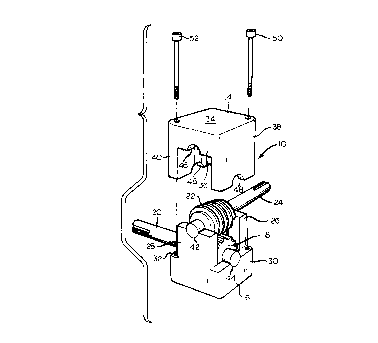
Fig. 2 is a perspective view at an enlarged scale of a gearbox of the type
1 S shown in Fig. 1; and
Fig. 3 is an exploded perspective view, at the scale of Fig. 2, of the
gearbox of Figs. 1 and 2.
DETAILED DESCRIPTION OF THE PREFERRED EMBODIMENT
Fig. 1 illustrates a glass container annealing lehr installation in which an
annealing lehr L has a conveyor C, for example, an endless wire mesh conveyor,
for
conveying freshly formed glass containers B on a cross-conveyor X through the
lehr L to
relief residual forming stresses in the containers B. The containers B are
transferred in
unison from the cross-conveyor X to the conveyor C by a pusher bar P of a
three-axis
lehr loader or stacker, which may be of conventional construction, the
containers B
3

CA 02281422 1999-09-03
17168
passing across a series of deadplates D on their way from the conveyor X to
the conveyor
C. From time to time it is necessary or desirable to be able to adjust the
elevation of an
upper flight of the conveyor X, for example, to be able to align the level of
the conveyor
X with the level of
the upper flight of the conveyor C, and to that end a plurality of manually
operated
adjustment mechanisms, each involving a right angle drive gearbox 10, are
provided.
As is shown in Fig. 2, a gearbox 10 has a housing 12 in the shape of a
parallelepiped, and the housing 12 is made up of upper and lower housing
members 14,
16. The housing 12, which has an internal cavity or space, encloses a driving
gear 18,
which is keyed or otherwise affixed to a driving shaft 20, and a driven gear
22, which is
keyed or otherwise affixed to a driven shaft 24 and is drivingly engaged by
the driving
gear 18. The longitudinal central axis of the driven shaft 24 is spaced from
the
longitudinal central axis of the driving shaft 20, and otherwise extends
perpendicularly
with respect thereto.
The lower housing member 16 has a bottom wall, not shown, a first
opposed, spaced apart like pair of upstanding side walls 26, 28, and a second
opposed,
spaced apart like pair of upstanding side walls 30, 32, the first side walls
26, 28 extending
a substantially greater distance from the bottom wall of the lower housing
member 16
than the second side walls 30, 32. Similarly, the upper housing member 14 has
a top wall
34, a first opposed, spaced apart like pair of side walls, only one of which,
the side wall
36, is shown, and a second opposed, spaced apart like pair of side walls 38,
40, the
second side walls 38, 40 extending a substantially greater distance from the
top wall 34
than the first side wall 36.
4

CA 02281422 1999-09-03
17168
Each of the first side walls 26, 28 of the lower housing member 16 has a
semi-cylindrical recess 42 in a free edge thereof, and each of the second side
walls of the
lower housing member 16, including the side wall 30, has a semi-cylindrical
recess 44 in
a free edge thereof. Likewise, each of the first side walls of the upper
housing member
14, including the side wall 36, has a semi-cylindrical recess 46 in a free
edge thereof, and
each of the second side walls 38, 40 of the upper housing member 14 has a semi-
cylindrical recess 48 in a free edge thereof. Thus, when the housing members
14, 16 are
removable joined together, threaded fasteners 50, 52 being provided to serve
that
purpose, the opposed recesses 42 of the lower housing member 16 are positioned
complementarily to the opposed recesses 46 of the upper housing member 14 to
form
cylindrical openings for rotatingly supporting the driven shaft 24, at
locations on opposite
sides of the driven gear 22. Likewise, when housing members 14, 16 are joined
together,
the opposed recesses 44 of the lower housing member 14 are positioned
complementarily
to the opposed recesses 48 of the upper housing member 14 to form cylindrical
openings
for rotatingly supporting the driving shaft 20 on opposite sides of the
driving gear 18. In
that regard, because the gearbox 10 is intended to be operated only
intermittently and
only under low levels of torque at that, the cylindrical openings defined by
the recesses
42, 46 and 44, 48 need not be provided with separate bearings or bushings, and
this
eliminates elements that would otherwise materially increase the cost of the
gearbox 10.
It is also to be noted that the upper housing member 14 can be readily
removed from the lower housing member 16, to inspect or replace the gears
18,22 or to
repair the housing 12, for example, and this can be done simply by the removal
of the
threaded fasteners 50, 52, as heretofore described. Thus, the gearbox 10 is
not only
relatively inexpensive, because it does not have and does not require separate
bearings or

CA 02281422 1999-09-03
17168
bushings to rotatingly support the shafts 20, 24, as heretofore described, but
it is also
quite simple to disassemble for purposes of repair or replacement of any of
its constituent
elements that are subject to wear or damage in operation. In fact, the fact
that separate
bushings or bearings are not used facilitates the disassembly of the housing
12. Also, the
fact that the gearbox 10 totally encloses the gears 18, 22, as it must to
ensure that the
recesses 42, 46 and 44, 48 are positioned complementarily to define
cylindrical openings,
as heretofore described, ensures that dirt and other foreign particles can be
kept out of
contaminating engagement with the gears 18, 22, and that a suitable lubricant,
such as a
viscous grease, can be kept in engagement with them.
Although the best mode contemplated by the inventor for carrying out the
present invention as of the filing date hereof has been shown and described
herein, it will
be apparent to those skilled in the art that suitable modifications,
variations, and
equivalents may be made without departing from the scope of the invention,
such scope
being limited solely by the terms of the following claims and the legal
equivalents
thereof.

Representative Drawing
A single figure which represents the drawing illustrating the invention.
Administrative Status

2024-08-01:As part of the Next Generation Patents (NGP) transition, the Canadian Patents Database (CPD) now contains a more detailed Event History, which replicates the Event Log of our new back-office solution.

Please note that "Inactive:" events refers to events no longer in use in our new back-office solution.

For a clearer understanding of the status of the application/patent presented on this page, the site Disclaimer , as well as the definitions for Patent , Event History , Maintenance Fee  and Payment History  should be consulted.

Event History

Description Date
Inactive: IPC deactivated 2019-01-19
Inactive: First IPC assigned 2018-09-27
Inactive: IPC assigned 2018-09-27
Inactive: IPC expired 2012-01-01
Time Limit for Reversal Expired 2004-09-03
Application Not Reinstated by Deadline 2004-09-03
Deemed Abandoned - Failure to Respond to Maintenance Fee Notice 2003-09-03
Amendment Received - Voluntary Amendment 2002-02-14
Amendment Received - Voluntary Amendment 2002-01-25
Letter Sent 2001-09-12
Request for Examination Received 2001-08-13
Request for Examination Requirements Determined Compliant 2001-08-13
All Requirements for Examination Determined Compliant 2001-08-13
Application Published (Open to Public Inspection) 2000-03-08
Inactive: Cover page published 2000-03-07
Inactive: First IPC assigned 1999-10-13
Inactive: IPC assigned 1999-10-13
Inactive: Filing certificate - No RFE (English) 1999-09-27
Filing Requirements Determined Compliant 1999-09-27
Letter Sent 1999-09-27
Application Received - Regular National 1999-09-23

Abandonment History

Abandonment Date Reason Reinstatement Date
2003-09-03

Maintenance Fee

The last payment was received on 2002-07-08

Note : If the full payment has not been received on or before the date indicated, a further fee may be required which may be one of the following

  • the reinstatement fee;
  • the late payment fee; or
  • additional fee to reverse deemed expiry.

Please refer to the CIPO Patent Fees web page to see all current fee amounts.

Fee History

Fee Type Anniversary Year Due Date Paid Date
Registration of a document 1999-09-03
Application fee - standard 1999-09-03
MF (application, 2nd anniv.) - standard 02 2001-09-03 2001-07-19
Request for examination - standard 2001-08-13
MF (application, 3rd anniv.) - standard 03 2002-09-03 2002-07-08
Owners on Record

Note: Records showing the ownership history in alphabetical order.

Current Owners on Record
OWENS-BROCKWAY GLASS CONTAINER INC.
Past Owners on Record
WILLIAM B. RUGH
Past Owners that do not appear in the "Owners on Record" listing will appear in other documentation within the application.
Documents

To view selected files, please enter reCAPTCHA code :


To view images, click a link in the Document Description column. To download the documents, select one or more checkboxes in the first column and then click the "Download Selected in PDF format (Zip Archive)" or the "Download Selected as Single PDF" button.

List of published and non-published patent-specific documents on the CPD .

If you have any difficulty accessing content, you can call the Client Service Centre at 1-866-997-1936 or send them an e-mail at CIPO Client Service Centre.


Document
Description 
Date
(yyyy-mm-dd) 
Number of pages   Size of Image (KB) 
Representative drawing 2000-02-21 1 8
Claims 2002-01-25 3 100
Description 2002-02-14 6 249
Description 1999-09-03 6 250
Abstract 1999-09-03 1 33
Claims 1999-09-03 3 98
Drawings 1999-09-03 2 41
Cover Page 2000-02-21 1 45
Courtesy - Certificate of registration (related document(s)) 1999-09-27 1 140
Filing Certificate (English) 1999-09-27 1 175
Reminder of maintenance fee due 2001-05-07 1 111
Acknowledgement of Request for Examination 2001-09-12 1 194
Courtesy - Abandonment Letter (Maintenance Fee) 2003-10-29 1 176