Note: Descriptions are shown in the official language in which they were submitted.
CA 02282005 1999-09-08
,
1
REMOVABLE SUPPORT ASSEMBLY FOR A TRAILER
FIELD OF THE INVENTION
The present invention relates to trailers in general, and more
particularly concerns a removable support assembly for adapting a wood
trailer to the transportation of logs of different sizes or of different
objects
altogether.
BACKGROUND
Trailers for transporting logs of wood or similar material generally
have a frame provided with two elongated side frame members onto which
are welded laterally disposed spaced-apart rails or bunks. These bunks
have extremities projecting beyond the side frame members, provided with
stakes to prevent side tipping of the logs. The bunks are welded onto the
side frame members and consequently their number is fixed. Depending on
the length of the logs to be carried, certain bunks with their stakes are
often useless, adding dead weight to the trailer. As the weight of material
that the trailer can carry is limited, the weight of these useless bunks and
2o their stakes limits the payload and reduces profits. In addition, the extra
weight increases gas expenses.
It is also known in the art to provide a single flat platform welded
onto the frame of a trailer. Sometimes only a limited portion of the
platform is used for transportation but the whole platform which is heavy
25 has to be carried by the frame, again adding dead weight to the trailer.
Wood transportation is a seasonal occupation, trailers for
transporting logs of wood usually being allowed circulation only during
winter when roads are frozen, so these roads wouldn't be damaged. Wood
trailers therefore become useless during the summer time. To avoid
3o interrupting business, trailer owners often have a second trailer provided
with a platform to work with during the hot seasons.
CA 02282005 1999-09-08
2
OBJECT AND SUMMARY OF THE INVENTION
It is therefore an object of the present invention to provide a
removable support assembly allowing to removably attach to a trailer
various support elements such as log bunks, bunk raisers, platforms or
sections of platforms.
It is a preferable object of the invention to provide such a removable
support assembly wherein each support element may be attached at
various positions on the trailer.
io Yet another preferable object of the invention is to provide a trailer
having a plurality of such removable support assemblies attached thereto.
Accordingly, the present invention provides a removable support
assembly for a trailer having an elongated top frame member, comprising:
at least one support element removably connectable to the top frame
member; and
connecting means for removably connecting the support element to
the top frame member.
In a first preferred embodiment, each of the at least one support
element is a log bunk. Each log bunk preferably comprises:
2o an elongated body having a first end and a second end, the first end
being connectable to the top frame member and the second end projecting
away from said top frame member; and
a stake pocket disposed at the second end of the elongated body for
receiving an extremity of a log stake.
In another preferred embodiment, each of the at least one support
element is a bunk raiser, each bunk raiser comprising:
a transverse beam sized to extend over the top frame member of the
trailer generally transversally thereto;
a pair of elongated bodies located respectively at both ends of the
3o transverse beam, each of the elongated bodies having a first end and a
second end, said first ends of the elongated bodies facing each other; and
CA 02282005 1999-09-08
.
3
a pair of stake pockets respectively disposed at the second
ends of the elongated bodies for receiving respective extremities of two
logstakes.
In another preferred embodiment, each of the at least one support
element is a platform section, each platform section comprising:
a platform surface; and
at least one platform support having a top beam for supporting said
platform surface, and a supporting structure for supporting the top beam,
said supporting structure being connectable to the top frame portion by
1o means of the connecting means.
In yet another preferred embodiment, the at least one support
element is a platform, said platform comprising:
a platform surface; and
a plurality of support beams for supporting said platform surface, the
is support beams extending transversally to the top frame member and being
connectable thereto by means of the connecting means.
Advantageously, the removable support assembly according to the
present invention allows a trailer to be adapted to the type of products
transported, may it be logs of a specific length or smaller objects
2o necessitating a platform surface, while minimizing the weight of the
trailer
itself.
Other features and advantages of the present invention will become
apparent upon reading the following descriptions of preferred embodiments
thereof with reference to the accompanying drawings.
BRIEF DESCRIPTION OF THE DRAWINGS
FIG. 1 is a perspective view of a trailer provided with removable
support assemblies according to a first preferred embodiment of the
invention, wherein the support elements are log bunks;
3o FIG. 1 A is an enlarged view of section 1 A of FIG. 1;
FIG. 1 B is a side elevation view of the section of FIG. 1 A;
CA 02282005 1999-09-08
4
FIG. 2 is a perspective view of a trailer provided with removable
support assemblies according to a second preferred embodiment of the
invention, wherein the support elements are also log bunks;
FIG. 2A is an enlarged view of section 2A of FIG. 2;
s FIG. 2B is a side elevation view of the section of FIG. 2A;
FIG. 2C is a view similar to FIG. 2B, showing how the log bunk is
connected to the top frame member of the trailer;
FIG. 3 is a perspective view of a trailer provided with removable
support assemblies according to a third preferred embodiment of the
1o invention, wherein the support elements are bunkraisers;
FIG. 3A is an enlarged view of section 3A of FIG. 3;
FIG. 3B is a side elevation view of the section of FIG. 3A;
FIG. 4 is a perspective view of a trailer provided with removable
support assemblies according to a fourth preferred embodiment of the
15 invention, wherein the support elements are also bunkraisers;
FIG. 4A is an enlarged view of section 4A of FIG. 4;
FIG. 4B is a side elevation view of the section of FIG. 4A;
FIG. 5 is a perspective view of a trailer provided with removable
support assemblies according to a fifth preferred embodiment of the
2o invention, wherein the support elements are platform sections;
FIG. 5A is an enlarged view of section 5A of FIG. 5;
FIG. 5B is a side elevation view of the section of FIG. 5A;
FIG. 6 is a perspective view of a trailer provided with removable
support assemblies according to a sixth preferred embodiment of the
2s invention, wherein the support element is a platform;
FIG. 6A is an enlarged view of section 6A of FIG. 6; and
FIG. 6B is a side elevation view of the section of FIG. 6A.
DESCRIPTION OF PREFERRED EMBODIMENTS OF THE INVENTION
3o In accordance with the present invention, a trailer may be adapted
for a variety of purposes by providing it with different kinds and different
CA 02282005 1999-09-08
numbers of removable support assemblies, each having at least one
support element removably connectable to the trailer via connecting
means. Different examples of such support assemblies are described
below.
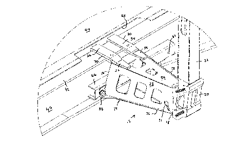
5 For example, referring now to Figs. 1, 1 A and 1 B, the trailer 10 has
an elongated top frame member 1 1 composed of two side beams 40, each
having a top portion 42. A floor 44 is preferably provided, fixed to the top
portions 42 of the side beams.
FIGs. 1, 1 A and 1 B all show a first embodiment of the invention. In
~o this embodiment, the support elements are embodied by log bunks 14. As
better seen in FIG. 1 A, each log bunk 14 has an elongated body, preferably
frustro-pyramidal in shape with a first end 16 and a second end 18. The
first end 16 is preferably wider than the second end 18. The first end 16 is
connectable to the top frame member 11. The narrow end 18 projects
~s away from the top frame member 11 of the trailer 10, and has a stake
pocket 20 for receiving a log stake 22. The log stakes 22 are used to
prevent the logs carried on the trailer 10 to roll off from the sides. An
oblong hole 21 is preferably provided on a side of the log bunk 14 to
receive a chain (not shown) connected to the stake 22, for holding said
2o stake 22 in the stake pocket 20. More particularly, each log bunk 14 has a
top wall 24, a bottom wall 26 and two side walls 28.
In this embodiment, the connecting means preferably include two
clamps 30, each attached to the top wall 24 of the corresponding log bunk
14 at one end 32 and being hook-shaped at the second end 34 for
2s connection by clamping to the top portion 42. Fasteners, such as bolts 36
and screws 38 are also provided for connecting the side walls 28 to the
side beam 40. Any other appropriate fasteners may also be used.
Preferably, sliding tracks 46 are disposed along each of the side beams 40
of the top frame portion 1 1, having screw holes 47 for receiving the
3o screws 38 at different possible positions along the side beams 40. In
addition, if the floor 44 is present on the top frame member 1 1, openings
CA 02282005 1999-09-08
6
48 are preferably provided in this floor 44 to expose parts of the top
portion 42 of the side beams, so that the hook-shaped extremities 34 of
the clamps 30 may be connected to the top portions 42. The openings 48
and sliding tracks 46 are preferably aligned, so as to define receiving areas
where the removable support assemblies may be connected at different
positions.
Referring to FIGs. 2, 2A, 2B and 2C, there is shown a second
embodiment of the invention similar to the one described above, as the
support elements are also log bunks 14 of the same shape as those of
FIGs. 1, 1 A and 1 B. However, in this embodiment, the top portion 42 of
each side beam 40 has a hook-shaped edge 50, projecting outwardly of
the top frame member 1 1, connectable to the hook-shaped extremities 34
of the clamps 30; in this manner, the clamps may be connected to the top
portion 42 of the side beams 40 from beneath, so that there is no longer
1s any need for openings 48 in the floor 44 of the trailer 10 as shown in
Fig.1 A. In this embodiment the sliding tracks 46 may extend along the
entire length of the side beams 40, since they do not need to be aligned
with the openings in the floor 44. In addition, the log bunk 14 in
accordance with this embodiment is easy to install on the trailer 10, as
2o illustrated in FIG. 2C. A user simply has to engage the hook-shaped
extremities 34 of the log bunk 14 to the hook-shaped edge 50, as shown
in FIG.2C, and then pivot the log bunk 14 in position. Similarly, the log
bunk 14 is removed by a pivotal movement thereof.
Referring to FIGs. 3, 3A, 3B, 4, 4A and 4B, there are shown other
25 embodiments of the invention where the support elements are bunk raisers
51. Bunk raisers essentially consist of two opposed log bunks connected
together by a beam extending across the top frame portion, and are used
to "raise" the logs of the load above and out of contact with the frame.
Accordingly, each bunk raiser 51 in these embodiments of the
3o invention has a transverse beam 52 sized to extend over the top frame
member 11 in a generally transversal manner. Two elongated bodies 15,
CA 02282005 1999-09-08
7
also preferably frustro-pyramidal in shape, are provided on each side of
the transverse beam 52, their first ends 16 facing each other. The second
ends 18 of each body 15 are provided with a stake pocket 20 for holding a
log stake 22. Preferably, the transverse beam 52 is integral to the
s elongated bodies 15.
As with the log bunks of the previous embodiments, the frustro-
pyramidal bodies 15 each have a top wall 24, a bottom wall 26 and side
walls 28. Preferably, the top wall 24 is embodied by a portion of the
transverse beam 52. Bolts 36 and screws 38, or any other appropriate
1o fasteners, are provided to connect the side walls to the side beams 40,
sliding tracks 46 being disposed along the side beams 40 for this purpose.
As shown in FIGs. 3A, 3B, 4A and 4B, a removable winch 94 can
optionally be installed on a side of the elongated body 15. Although shown
with respect to bunk raisers, winches 94 may be installed on any
15 appropriate support element. In the preferred embodiment, the winch 94 is
removably fixed to a side wall 28 of a frustro-pyramidal body, through
bolts and screws or other fasteners. The winch 94 is for receiving a chain
or rope used to tie up the payload on the trailer, and can be installed on
any number of bunks, bunk raisers or other support elements, on the side
2o chosen by the operator.
As the bunk raisers 51 are supported on top of the top frame
member 1 1 and do not need to be connected to the top portion 42 of each
side beam 40, they can be installed either on the trailer of FIG. 1, as seen
in FIGs. 3, 3A and 3B), or the trailer of FIG. 2. (as seen in FIGs. 4, 4A and
25 4B) .
Referring to FIGs. 5, 5A and 5B, there is shown yet another
embodiment of the invention where the support elements are platform
sections 54. Each platform section preferably has a platform surface 56,
supported by at least one platform support 58, which is preferably
3o triangular in shape. The platform support 58 has a top beam 60, for
supporting the platform surface 56, and a supporting structure for
CA 02282005 1999-09-08
8
supporting the top beam, preferably in the form of a pair of support
beams 62. The support beams 62 have their respective first extremities 64
attached to the top beam 60, one near the front and the other near the
back, and their second extremities 66 projecting away from the top beam
s 60 and meeting at a joining point which is connectable to the top frame
portion 11. In the preferred embodiment, a plate 68 is rigidly attached to
the second extremities 66 of the support beams, perpendicularly thereto,
and bolts 36 and screws 38 or other fasterners are provided for connecting
the plate 68 to the top frame portion 11 of the trailer 10, preferably on
1o sliding tracks 46.
In accordance with this embodiment, the connecting means further
include at least one clamp 70 for each platform section 54, having a first
extremity 72 attached to the platform section, and a hook-shaped second
extremity 74 connectable by clamping to the top portion 42.
is Advantageously, the top portion 42 of the side beams 40 may have a
hook-shaped edge 50 to which the hook-shaped second extremity 74 of
the clamp 70 is connected.
FIGs. 6, 6A and 6B show another embodiment of the invention,
where the support element is a one piece platform 76. The platform 76
2o preferably includes a platform surface 78 supported by a plurality of
support beams 80 disposed transversally on the top frame member 11.
Each support beam 80 has an inverted T-shaped bottom portion 82. The
connecting means include a pair of connecting clamps 84 for each support
beam 80, for connecting respectively two remote portions of the support
2s beam 80 to the side beams 40 of the top frame member 11. The top
portions 42 of the side beams 40 are also T-shaped, and each connecting
clamp 84 has two clamping members 86 for clamping together the T-
shaped top and bottom portions 42 and 82 of the respective side and
support beams 40 and 80. A screw 90, extending through the clamping
3o members 86 and a bolt 88, are provided for tightening the clamping
members 86 together with the T-shaped top and bottom portions 42 and
CA 02282005 1999-09-08
9
82 therebetween. Any other tightening means may of course be
used for this purpose.
The present invention also concerns a trailer provided with any of
the removable support assembly described in the above embodiments, in
any number. It is also within the scope of the invention to provide a single
trailer having different types of support assemblies, such as, for example,
covering a portion of the trailer with platform sections and the rest with log
bunks, allowing for the mixed transport of merchandise.
Of course, numerous modifications could be made to the
io embodiments described above without departing from the scope of the
invention as defined in the appended claims.