Note: Descriptions are shown in the official language in which they were submitted.
CA 02282188 1999-09-15
INTERMITTENT ELECTROCOAGULATION
PRINTING METHOD AND APPARATUS
The present invention pertains to improvements
s in the field of electrocoagulation printing. More
particularly, the invention relates to an intermittent
electrocoagulation printing method and apparatus.
In US Patent No. 4,895,629 of January 23, 1990,
~o Applicant has described a high-speed electrocoagulation
printing method and apparatus in which use is made of a
positive electrode in the form of a revolving cylinder
having a passivated surface onto which dots of colored,
coagulated colloid representative of an image are
15 produced. These dots of colored, coagulated colloid are
thereafter contacted with a substrate such as paper to
cause transfer of the colored, coagulated colloid onto
the substrate and thereby imprint the substrate with the
image. As explained in this patent, the positive
zo electrode is coated with a dispersion containing an
olefinic substance and a metal oxide prior to electrical
energization of the negative electrodes in order to
weaken the adherence of the dots of coagulated colloid to
the positive electrode and also to prevent an
zs uncontrolled corrosion of the positive electrode. In
addition, gas generated as a result of electrolysis upon
energizing the negative electrodes is consumed by
reaction with the olefinic substance so that there is no
gas accumulation between the negative and positive
3o electrodes.
The electrocoagulation printing ink which is
injected into the gap defined between the positive and
negative electrodes consists essentially of a liquid
3s colloidal dispersion containing an electrolytically
coagulable colloid, a dispersing medium, a soluble
electrolyte and a coloring agent. Where the coloring
- 1 -
CA 02282188 1999-09-15
agent used is a pigment, a dispersing agent is added for
uniformly dispersing the pigment into the ink. After
coagulation of the colloid, any remaining non-coagulated
colloid is removed from the surface of the positive
s electrode, for example, by scraping the surface with a
soft rubber squeegee, so as to fully uncover the colored,
coagulated colloid which is thereafter transferred onto
the substrate. The surface of the positive electrode is
thereafter cleaned by means of a plurality of rotating
~o brushes and a cleaning liquid to remove any residual
coagulated colloid adhered to the surface of the positive
electrode.
When a polychromic image is desired, the
~s negative and positive electrodes, the positive electrode
coating device, ink injector, rubber squeegee and
positive electrode cleaning device are arranged to define
a printing unit and several printing units each using a
coloring agent of different color are disposed in tandem
2o relation to produce several differently colored images of
coagulated colloid which are transferred at respective
transfer stations onto the substrate in superimposed
relation to provide the desired polychromic image. Alter-
natively, the printing units can be arranged around a
zs single roller adapted to bring the substrate into contact
with the dots of colored, coagulated colloid produced by
each printing unit, and the substrate which is in the
form of a continuous web is partially wrapped around the
roller and passed through the respective transfer
3o stations for being imprinted with the differently colored
images in superimposed relation.
The positive electrode which is used for
electrocoagulation printing must be made of an
ss electrolytically inert metal capable of releasing
trivalent ions so that upon electrical energization of
the negative electrodes, dissolution of the passive oxide
- 2 -
CA 02282188 1999-09-15
film on such an electrode generates trivalent ions which
then initiate coagulation of the colloid. Examples of
suitable electrolytically inert metals include stainless
steels, aluminium and tin.
As explained in Applicant's Canadian patent
No. 2,138,190 of October 13, 1998, a breakdown of passive
oxide films occurs in the presence of electrolyte anions,
such as C1-, Br- and I-, there being a gradual oxygen
~o displacement from the passive film by the halide anions
and a displacement of adsorbed oxygen from the metal
surface by the halide anions. The velocity of passive
film breakdown, once started, increases explosively in
the presence of an applied electric field. There is thus
formation of a soluble metal halide at the metal surface.
In other words, a local dissolution of the passive oxide
film occurs at the breakdown sites, which releases metal
ions into the electrolyte solution. Where a positive
electrode made of stainless steel or aluminium is
zo utilized in Applicant's electrocoagulation printing
method, dissolution of the passive oxide film on such an
electrode generates Fe3+ or A13+ ions. These trivalent
ions then initiate coagulation of the colloid.
zs When using negative electrodes made of an
active metal such as iron, Applicant has observed that
the metal undergoes dissolution in the ink in the
presence of the aforesaid electrolyte anions, whether the
electrodes are energized or not, resulting in corrosion
30 of the negative electrodes and contamination of the ink.
In addition, the metal ions which are released into the
ink as a result of such a dissolution cause the formation
of a gelatinous material which deposits onto the surfaces
of the negative electrodes, thereby creating an
35 electrical resistance which increases as the amount of
- 3 -
CA 02282188 1999-09-15
deposited gelatinous material increases, leading to a
complete blocking of the electrical signal.
When using negative electrodes made of a
s passive metal such as chromium, nickel, stainless steel
and titanium which have a passive oxide film on their
surface, Applicant has observed that when the electrodes
are not energized, there is no formation of the aforesaid
gelatinous deposit. On the other hand, when the negative
~o electrodes are energized, there is formation of the
gelatinous deposit. It is believed that gas generated as
a result of electrolysis and not consumed by reaction
with the aforesaid olefinic substance causes a breakdown
of the passive oxide film and a local dissolution of the
15 latter at the breakdown sites, resulting in a release of
metal ions into the ink and formation of the gelatinous
deposit.
It is therefore an object of the present
zo invention to overcome the above drawbacks and to provide
an improved electrocoagulation printing method and
apparatus, wherein undesirable formation of the above
gelatinous deposit is avoided.
z5 According to one aspect of the invention, there
is provided an electrocoagulation printing method
comprising the steps of:
a) providing a positive electrolytically inert
3o electrode having a continuous passivated surface moving
at substantially constant speed along a predetermined
path, the passivated surface defining a positive
electrode active surface;
35 b) forming on the positive electrode active
surface a plurality of dots of colored, coagulated
colloid representative of a desired image, by
- 4 -
CA 02282188 1999-09-15
electrocoagulation of an electrolytically coagulable
colloid present in an electrocoagulation printing ink
comprising a liquid colloidal dispersion containing the
electrolytically coagulable colloid, a dispersing medium,
s a soluble electrolyte and a coloring agent; and
c) bringing a substrate into contact with the
dots of colored, coagulated colloid to cause transfer of
the colored, coagulated colloid from the positive
~o electrode active surface onto the substrate and thereby
imprint the substrate with the image;
the improvement wherein step (b) is carried out by:
i) providing a first and a second series of
negative electrolytically inert electrodes each having a
surface covered with a passive oxide film, the negative
electrodes of each series being electrically insulated
from one another and arranged in rectilinear alignment so
zo that the surfaces thereof define a plurality of
corresponding negative electrode active surfaces disposed
in a respective plane spaced from the positive electrode
active surface by a respective constant predetermined
gap, the first and second series of negative electrodes
zs being arranged in spaced-apart parallel relationship with
the negative electrodes of each series being spaced from
one another by a distance at least equal to the
respective electrode gap;
3o ii) coating the positive electrode active
surface with an olefinic substance to form on the surface
micro-droplets of olefinic substance;
iii) filling the electrode gaps with the
35 aforesaid electrocoagulation printing ink;
- 5 -
CA 02282188 1999-09-15
iv) electrically energizing selected ones of
the negative electrodes of the first and second series in
a controlled alternate manner such that the electrodes of
the first series are energized prior to an undesirable
s formation of a gelatinous deposit on the electrode active
surface of each energized electrode of the second series
and the electrodes of the second series are energized
prior to an undesirable formation of a further gelatinous
deposit on the electrode active surface of each energized
to electrode of the first series, thereby causing point-by
point selective coagulation and adherence of the colloid
onto the olefin-coated positive electrode active surface
opposite the electrode active surfaces of the energized
negative electrodes while the positive electrode active
~s surface is moving; and
v) removing any remaining non-coagulated
colloid from the positive electrode active surface.
2o According to another aspect of the invention,
there is also provided an electrocoagulation printing
apparatus comprising:
- a positive electrolytically inert electrode
z5 having a continuous passivated surface defining a
positive electrode active surface;
- means for moving the positive electrode
active surface at a substantially constant speed along a
3o predetermined path;
- means for forming on the positive electrode
active surface a plurality of dots of colored, coagulated
colloid representative of a desired image, by
s5 electrocoagulation of an electrolytically coagulable
colloid present in an electrocoagulation printing ink
comprising a liquid colloidal dispersion containing the
- 6 -
CA 02282188 1999-09-15
electrolytically coagulable colloid, a dispersing medium,
a soluble electrolyte and a coloring agent; and
- means for bringing a substrate into contact
s with the dots of colored, coagulated colloid to cause
transfer of the colored, coagulated colloid from the
positive electrode active surface onto the substrate and
thereby imprint the substrate with the image;
~o the improvement wherein the means for forming the dots of
colored, coagulated colloid comprise:
- a first and a second series of negative
electrolytically inert electrodes each having a surface
covered with a passive oxide film, the negative
electrodes of each series being electrically insulated
from one another and arranged in rectilinear alignment so
that the surfaces thereof define a plurality of
corresponding negative electrode active surfaces disposed
zo in a respective plane spaced from the positive electrode
active surface by a respective constant predetermined
gap, the first and second series of negative electrodes
being arranged in spaced-apart parallel relationship with
the negative electrodes of each series being spaced from
zs one another by a distance at least equal to the
respective electrode gap;
- means for coating the positive electrode
active surface with an olefinic substance to form on the
3o surface micro-droplets of olefinic substance;
- means for filling the electrode gaps with the
electrocoagulation printing ink;
35 - means for electrically energizing selected
ones of the negative electrodes of the first and second
series in a controlled alternate manner such that the
CA 02282188 1999-09-15
electrodes of the first series are energized prior to an
undesirable formation of a gelatinous deposit on the
electrode active surface of each energized electrode of
the second series and the electrodes of the second series
s are energized prior to an undesirable formation of a
further gelatinous deposit on the electrode active
surface of each energized electrode of the first series,
thereby causing point-by-point selective coagulation and
adherence of the colloid onto the olefin-coated positive
~o electrode active surface opposite the electrode active
surfaces of the energized negative electrodes while the
positive electrode active surface is moving; and
- means for removing any remaining non
coagulated colloid from the positive electrode active
surface .
Applicant has found quite unexpectedly that by
providing two series of negative electrolytically inert
zo electrodes each having a surface covered with a passive
oxide film and electrically energizing selected ones of
the negative electrodes of these two series in a
controlled alternate manner as defined above, the
aforesaid gelatinous deposit does not form in an amount
zs sufficient to create an electrical resistance which is
detrimental to the electrocoagulation. It is believed
that the passive oxide film of each energized electrode
does not dissolve into the ink in a quantity sufficient
to cause an undesirable formation of the gelatinous
so deposit and, upon de-energization, the passive oxide film
rebuilds itself due to the presence of oxidizing
substances in the ink. Preferably, the energizing of the
negative electrodes of the first and second series is
controlled to provide a continous formation of the dots
35 Of colored, coagulated colloid on the positive electrode
active surface.
_ g _
CA 02282188 1999-09-15
According to a preferred embodiment, the
negative electrodes of each series are mounted to a
respective elongated electrode carrier along the length
thereof. It is also possible to mount the negative
electrodes of the first and second series to a single
elongated electrode carrier along the length thereof.
Preferably, the negative electrodes of the first and
second series each have a cylindrical configuration with
a circular cross-section and a diameter ranging from
1o about 20 ~ to about 50 ~,. Where the negative electrodes
are mounted to a single electrode carrier, the first and
second series of such negative electrodes are spaced from
one another by a distance ranging from about 250 to about
1000 ~..
As explained in Applicant's US Patent
No. 4,895,629, spacing of the negative electrodes from
one another by a distance which is equal to or greater
than the electrode gap prevents the negative electrodes
zo from undergoing edge corrosion. On the other hand,
coating of the positive electrode with an olefinic
substance prior to electrical energization of the
negative electrodes weakens the adherence of the dots of
coagulated colloid to the positive electrode and also
z5 prevents an uncontrolled corrosion of the positive
electrode. In addition, gas generated as a result of
electrolysis upon energizing the negative electrodes is
consumed by reaction with the olefinic substance so that
there is no gas accumulation between the negative and
3o positive electrodes. Applicant has found that it is no
longer necessary to admix a metal oxide with the olefin
substance; it is believed that the passive oxide film on
currently available electrode contains sufficient metal
oxide to act as catalyst for the desired reaction.
Examples of suitable electrolytically inert
metals from which the negative electrodes can be made
_ g _
CA 02282188 1999-09-15
include chromium, nickel, stainless steel and titanium;
stainless steel is particularly preferred. The positive
electrode, on the other hand, can be made of stainless
steel, tin or aluminum. The gap which is defined between
s the positive and negative electrodes can range from about
35 ~, to about 100 ~, the smaller the electrode gap the
sharper are the dots of coagulated colloid produced.
Where the electrode gap is of the order of 50 ~,, the
negative electrodes are preferably spaced from one
~o another by a distance of about 75
Examples of suitable olefinic substances which
may be used to coat the surface of the positive electrode
in step (b)(ii) include unsaturated fatty acids such as
~s arachidonic acid, linoleic acid, linolenic acid, oleic
acid and palmitoleic acid and unsaturated vegetable oils
such as corn oil, linseed oil, olive oil, peanut oil,
soybean oil and sunflower oil. Oleic acid is particularly
preferred. The micro-droplets formed on the surface of
2o the positive electrode active surface generally have a
size ranging from about 1 to about 5 ~,.
The olefin-coated positive active surface is
preferably polished to increase the adherence of the
2s micro-droplets onto the positive electrode active
surface, prior to step (b) (ii) . For example, use can be
made of a rotating brush provided with a plurality of
radially extending bristles made of horsehair and having
extremities contacting the surface of the positive
3o electrode. The friction caused by the bristles contacting
the surface upon rotation of the brush has been found to
increase the adherence of the micro-droplets onto the
positive electrode active surface.
35 Where a polychromic image is desired, steps (b)
and (c) of the above electrocoagulation printing method
are repeated several times to define a corresponding
- 10 -
CA 02282188 1999-09-15
number of printing stages arranged at predetermined
locations along the aforesaid path and each using a
coloring agent of different color, and to thereby produce
several differently colored images of coagulated colloid
s which are transferred at the respective transfer
positions onto the substrate in superimposed relation to
provide a polychromic image. It is also possible to
repeat several times steps (a), (b) and (c) to define a
corresponding number of printing stages arranged in
to tandem relation and each using a coloring agent of
different color, and to thereby produce several
differently colored images of coagulated colloid which
are transferred at respective transfer positions onto the
substrate in superimposed relation to provide a
polychromic image, the substrate being in the form of a
continuous web which is passed through the respective
transfer positions for being imprinted with the colored
images at the printing stages. Alternatively, the
printing stages defined by repeating several times steps
zo (a), (b) and (c) can be arranged around a single roller
adapted to bring the substrate into contact with the dots
of colored, coagulated colloid of each printing stage and
the substrate which is in the form of a continuous web is
partially wrapped around the roller and passed through
z5 the respective transfer positions for being imprinted
with the colored images at the printing stages . The last
two arrangements are described in US Patent No.
4,895,629.
3o When a polychromic image of high definition is
desired, it is preferable to bring an endless non-
extensible belt moving at substantially the same speed as
the positive electrode active surface and having on one
side thereof a colloid retaining surface adapted to
35 releasably retain dots of electrocoagulated colloid to
cause transfer of the differently colored images at the
respective transfer positions onto the colloid retaining
- 11 -
CA 02282188 1999-09-15
surface of such a belt in superimposed relation to
provide a polychromic image, and thereafter bring the
substrate into contact with the colloid retaining surface
of the belt to cause transfer of the polychromic image
from the colloid retaining surface onto the substrate and
to thereby imprint the substrate with the polychromic
image. As explained in Applicant's copending Canadian
patent application No. 2,214,300 filed August 29, 1997,
by utilizing an endless non-extensible belt having a
~o colloid retaining surface such as a porous surface on
which dots of colored, coagulated colloid can be
transferred and by moving such a belt independently of
the positive electrode, from one printing unit to
another, so that the colloid retaining surface of the
belt contacts the colored, coagulated colloid in
sequence, it is possible to significantly improve the
registration of the differently colored images upon their
transfer onto the colloid retaining surface of the belt,
thereby providing a polychromic image of high definition
2o which can thereafter be transferred onto the paper web or
other substrate. For example, use can be made of a .belt
comprising a plastic material having a porous coating of
silica.
z5 Accordingly, the present invention also
provides, in a further aspect thereof, an improved
multicolor electrocoagulation printing method comprising
the steps of
3o a) providing a positive electrolytically inert
electrode having a continuous passivated surface moving
at substantially constant speed along a predetermined
path, the passivated surface defining a positive
electrode active surface;
b) forming on the positive electrode active
surface a plurality of dots of colored, coagulated
- 12 -
CA 02282188 1999-09-15
colloid representative of a desired image, by
electrocoagulation of an electrolytically coagulable
colloid present in an electrocoagulation printing ink
comprising a liquid colloidal dispersion containing the
electrolytically coagulable colloid, a dispersing medium,
a soluble electrolyte and a coloring agent;
c) bringing an endless non-extensible belt
having a porous surface on one side thereof and moving at
~o substantially the same speed as the positive electrode
active. surface, into contact with the positive electrode
active surface to cause transfer of the dots of colored,
coagulated colloid from the positive electrode active
surface onto the porous surface of the belt and to
thereby imprint the porous surface with the image;
d) repeating steps (b) and (c) several times to
define a corresponding number of printing stages arranged
at predetermined locations along the path and each using
zo a coloring agent of different color, to thereby produce
several differently colored images of coagulated colloid
which are transferred at respective transfer positions
onto the porous surface in superimposed relation to
provide a polychromic image; and
e) bringing a substrate into contact with the
porous surface of the belt to cause transfer of the
polychromic image from the porous surface onto the
substrate and to thereby imprint the substrate with the
so polychromic image;
the improvement wherein step (b) is carried out as
defined above.
According to yet another aspect of the
invention, there is provided an improved
electrocoagulation printing apparatus comprising:
- 13 -
CA 02282188 1999-09-15
- a positive electrolytically inert electrode having a
continuous passivated surface defining a positive
electrode active surface;
- means for moving the positive electrode active surface
at a substantially constant speed along a predetermined
path;
- an endless non-extensible belt having a porous surface
on one side thereof;
- means for moving the belt at substantially the same
speed as the positive electrode active surface;
- a plurality of printing units arranged at predetermined
locations along the path, each printing unit comprising:
- means for forming on the positive electrode
zo active surface a plurality of dots of colored, coagulated
colloid representative of a desired image, by
electrocoagulation of an electrolytically coagulable
colloid present in an electrocoagulation printing ink
comprising a liquid colloidal dispersion containing the
z5 electrolytically coagulable colloid, a dispersion medium,
a soluble electrolyte and a coloring agent, and
- means for bringing the belt into contact with
the positive electrode active surface at a respective
so transfer station to cause transfer of the dots of
colored, coagulated colloid from the positive electrode
active surface onto the porous surface of the belt and to
imprint the porous surface with the image,
35 thereby producing several differently colored images of
coagulated colloid which are transferred at the
- 14 -
CA 02282188 1999-09-15
respective transfer stations onto the porous surface in
superimposed relation to provide a polychromic image; and
- means for bringing a substrate into contact
s with the porous surface of the belt to cause transfer of
the polychromic image from the porous surface onto the
substrate and to thereby imprint the substrate with the
polychromic image;
~o the improvement wherein the means for forming the dots of
colored, coagulated colloid are as defined above.
The positive electrode used can be in the form
of a moving endless belt as described in Applicant's US
15 Patent No. 4,661,222, or in the form of a revolving
cylinder as described in Applicant's US Patent
Nos. 4,895,629 and 5,538,601. In the latter case, the
printing stages or units are arranged around the positive
cylindrical electrode. Preferably, the positive electrode
zo active surface and the ink are maintained at a tem-
perature of about 35-60°C, preferably 40°C, to increase
the viscosity of the coagulated colloid in step (b) so
that the dots of colored, coagulated colloid remain
coherent during their transfer in step (c), thereby
z5 enhancing transfer of the colored, coagulated colloid
onto the substrate or belt. For example, the positive
electrode active surface can be heated at the desired
temperature and the ink applied on the heated electrode
surface to cause a transfer of heat therefrom to the ink.
Where the positive cylindrical electrode
extends vertically, step (b)(ii) of the above electro-
coagulation printing method is advantageously carried out
by continuously discharging the ink onto the positive
3s electrode active surface from a fluid discharge means
disposed adjacent the electrode gap at a predetermined
height relative to the positive electrode and allowing
- 15 -
CA 02282188 1999-09-15
the ink to flow downwardly along the positive electrode
active surface, the ink being thus carried by the
positive electrode upon rotation thereof to the electrode
gap to fill same. Preferably, excess ink flowing
s downwardly off the positive electrode active surface is
collected and the collected ink is recirculated back to
the fluid discharge means.
The colloid generally used is a linear colloid
~o of high molecular weight, that is, one having a weight
average molecular weight between about 10,000 and about
1,000,000, preferably between 100,000 and 600,000.
Examples of suitable colloids include natural polymers
such as albumin, gelatin, casein and agar, and synthetic
15 polymers such as polyacrylic acid, polyacrylamide and
polyvinyl alcohol. A particularly preferred colloid is an
anionic copolymer of acrylamide and acrylic acid having a
weight average molecular weight of about 250,000 and sold
by Cyanamid Inc. under the trade mark ACCOSTRENGTH 86.
zo Water is preferably used as the medium for dispersing the
colloid to provide the desired colloidal dispersion.
The ink also contains a soluble electrolyte and
a coloring agent. Preferred electrolytes include alkali
2s metal halides and alkaline earth metal halides, such as
lithium chloride, sodium chloride, potassium chloride and
calcium chloride. Potassium chloride is particularly
preferred. The coloring agent can be a dye or a pigment.
Examples of suitable dyes which may be used to color the
3o colloid are the water soluble dyes available from HOECHST
such as Duasyn Acid Black for coloring in black and
Duasyn Acid Blue for coloring in cyan, or those available
from RIEDEL-DEHAEN such as Anti-Halo Dye Blue T. Pina for
coloring in cyan, Anti-Halo Dye AC Magenta Extra VO1 Pina
35 for coloring in magenta and Anti-Halo Dye Oxonol Yellow
N. Pina for coloring in yellow. When using a pigment as a
coloring agent, use can be made of the pigments which are
- 16 -
CA 02282188 1999-09-15
available from CABOT CORP. such as Carbon Black Monarch~
120 for coloring in black, or those available from
HOECHST such as Hostaperm Blue B2G or B3G for coloring
in cyan, Permanent Rubine F6B or L6B for coloring in
s magenta and Permanent Yellow DGR or DHG for coloring in
yellow. A dispersing agent is added for uniformly
dispersing the pigment into the ink. Examples of suitable
dispersing agents include the anionic dispersing agent
sold by Boehme Filatex Canada Inc. under the trade mark
1o CLOSPERSE 25000.
After coagulation of the colloid, any remaining
non-coagulated colloid is removed from the positive
electrode active surface, for example, by scraping the
surface with a soft rubber squeegee, so as to fully
uncover the colored, coagulated colloid. Preferably, the
non-coagulated colloid thus removed is collected and
mixed with the collected ink, and the collected non-
coagulated colloid in admixture with the collected ink is
zo recirculated back to the aforesaid fluid discharge means.
The optical density of the dots of colored,
coagulated colloid may be varied by varying the voltage
and/or pulse duration of the pulse-modulated signals
z5 applied to the negative electrodes.
After step (c), the positive electrode active
surface is generally cleaned to remove therefrom any
remaining coagulated colloid. According to a preferred
3o embodiment, the positive electrode is rotatable in a
predetermined direction and any remaining coagulated
colloid is removed from the positive electrode active
surface by providing an elongated rotatable brush
extending parallel to the longitudinal axis of the
35 positive electrode, the brush being provided with a
plurality of radially extending bristles made of
horsehair and having extremities contacting the positive
- 17 -
CA 02282188 1999-09-15
electrode active surface, rotating the brush in a
direction opposite to the direction of rotation of the
positive electrode so as to cause the bristles to
frictionally engage the positive electrode active
s surface, and directing jets of cleaning liquid under
pressure against the positive electrode active surface,
from either side of the brush. In such an embodiment, the
positive electrode active surface and the ink are
preferably maintained at a temperature of about 35-60°C
~o by heating the cleaning liquid to thereby heat the
positive electrode active surface upon contacting same
and applying the ink on the heated electrode surface to
cause a transfer of heat therefrom to the ink.
Preferably, the electrocoagulation printing ink
contains water as the dispersing medium and the dots of
differently colored, coagulated colloid representative of
the polychromic image are moistened between the
aforementioned steps (d) and (e) so that the polychromic
zo image is substantially completely transferred onto the
substrate in step (e).
According to another preferred embodiment, the
substrate is in the form of a continuous web and step (e)
zs is carried out by providing a support roller and a
pressure roller extending parallel to the support roller
and pressed thereagainst to form a nip through which the
belt is passed, the support roller and pressure roller
being driven by the belt upon movement thereof, and
3o guiding the web so as to pass through the nip between the
pressure roller and the porous surface of the belt for
imprinting the web with the polychromic image.
Preferably, the belt with the porous surface thereof
imprinted with the polychromic image is guided so as to
35 travel along a path extending in a plane intersecting the
longitudinal axis of the positive electrode at right
angles, thereby exposing the porous surface to permit
- 18 -
CA 02282188 1999-09-15
contacting thereof by the web. Where the longitudinal
axis of the positive electrode extends vertically, the
belt is preferably guided so as to travel along a
horizontal path with the porous surface facing
s downwardly, the support roller and pressure roller having
rotation axes disposed in a plane extending perpendicular
to the horizontal path. Such an arrangement is described
in the aforementioned Canadian application No. 2,214,300.
~o After step (e) , the porous surface of the belt
is generally cleaned to remove therefrom any remaining
coagulated colloid. According to a preferred embodiment,
any remaining coagulated colloid is removed from the
porous surface of the belt by providing at least one
elongated rotatable brush disposed on the one side of the
belt and at least one support roller extending parallel
to the brush and disposed on the opposite side of the
belt, the brush and support roller having rotation axes
disposed in a plane extending perpendicular to the belt,
zo the brush being provided with a plurality of radially
extending bristles made of horsehair and having
extremities contacting the porous surface, rotating the
brush in a direction opposite to the direction of
movement of the belt so as to cause the bristles to
z5 fractionally engage the porous surface while supporting
the belt with the support roller, directing jets of
cleaning liquid under pressure against the porous surface
from either side of the brush and removing the cleaning
liquid with any dislodged coagulated colloid from the
3o porous surface .
Further features and advantages of the
invention will become more readily apparent from the
description of preferred embodiments as illustrated by
35 way of examples in the accompanying drawings, in which:
- 19 -
CA 02282188 1999-09-15
Figure 1 is a fragmentary sectional view of an
electrocoagulation printing apparatus according to a
preferred embodiment of the invention, showing one
printing head with two series of negative electrodes;
Figure 2 is a fragmentary longitudinal view of
the printing head illustrated in Fig. 1;
Figure 3 is a fragmentary sectional view of an
~o electrocoagulation printing apparatus according to
another preferred embodiment of the invention, showing
two printing heads each having a respective series of
negative electrodes;
Figure 4 is a fragmentary longitudinal view of
one of the printing heads illustrated in Fig. 3;
Figure 5 is a fragmentary longitudinal view of
the other printing head illustrated in Fig. 3;
zo
Figure 6 is a fragmentary sectional view of one
of the negative electrodes illustrated in Figs . 1 and 3 ;
and
zs Figure 7 is a schematic diagram showing how an
input signal of information is processed to reproduce an
image by electrocoagulation of a colloid.
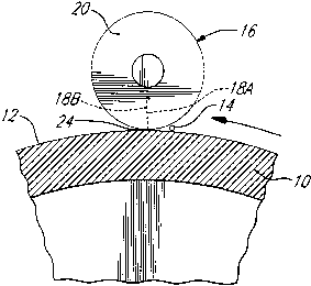
Referring first to Fig. 1, there is illustrated
3o a positive electrode 10 in the form of a revolving
cylinder and having a passivated surface 12 defining a
positive electrode active surface adapted to be coated
with an olefinic substance by means of a positive
electrode coating device (not shown). A device 14 is
35 provided for discharging an electrocoagulation printing
ink onto the surface 12. The electrocoagulation printing
ink consists of a colloidal dispersion containing an
- 20 -
CA 02282188 1999-09-15
electrolytically coagulable colloid, a dispersing medium,
a soluble electrolyte and a coloring agent. A printing
head 16 having two series of negative electrodes 18A,18B
is used for electrocoagulating the colloid contained in
s the ink to form on the positive electrode surface 12 dots
of colored, coagulated colloid representative of a
desired image. As shown in Fig. 2, the printing head 16
comprises a cylindrical electrode carrier 20 with the
respective negative electrodes 18A,18B of each series
~o being electrically insulated from one another and
arranged in rectilinear alignment along the length of the
electrode carrier 20 to define a plurality of
corresponding negative active surfaces 22A,22B. The two
series of negative electrodes 18A,18B are arranged in a
close spaced-apart parallel relationship. The printing
head 16 is positioned relative to the positive electrode
such that the surfaces 22A,22B of the negative
electrodes 18A,18B are disposed in a plane which is
spaced from the positive electrode surface 12 by a
zo constant predetermined gap 24. The respective electrodes
18A,18B of each series are also spaced from one another
by a distance at least equal to the electrode gap 24 to
prevent edge corrosion of the negative electrodes. The
device 14 is positioned adjacent the electrode gap 24 to
z5 fill same with the electrocoagulation printing ink.
Instead of using a single printing head 16 with
two series of negative electrodes 18A,18B, it is also
possible to use two printing heads 16A, 16B each having a
3o respective series of negative electrodes 18~A,18~B, as in
the embodiment illustrated in Figs 3-5. As shown, the
first printing head 16A comprises a cylindrical electrode
carrier 20A with the series of negative electrodes 18~A
being electrically insulated from one another and
3s arranged in rectilinear alignment along the length of the
electrode carrier 20A to define a plurality of
corresponding negative electrode active surfaces 22~A.
- 21 -
CA 02282188 1999-09-15
The printing head 16A is positioned relative to the
positive electrode 10' such that the surfaces 22'A of the
negative electrodes 18'A are disposed in a plane which is
spaced from the positive electrode surface 12' by a
s constant predetermined gap 24A. The electrodes 18'A are
also spaced from one another by a distance at least equal
to the electrode gap 24A to prevent edge corrosion of the
negative electrodes . A device 14A is associated with the
printing head 16A and positioned adjacent the electrode
~o gap 24A to fill same with the aforementioned
electrocoagulation printing ink.
Similarly, the second printing head 16B
comprises a cylindrical electrode carrier 20B with a
series of negative electrodes 18'B being electrically
insulated from one another and arranged in rectilinear
alignment along the length of the electrode carrier 20B
to define a plurality of corresponding negative electrode
active surfaces 22'B. The printing head 16B is positioned
zo relative to the positive electrode 10' such that the
surfaces 22'B of the negative electrodes 18'B are
disposed in a plane which is spaced from the positive
electrode surface 12' by a constant predetermined gap
24B. The electrodes 18'B are also spaced from one another
z5 by a distance at least equal to the electrode gap 24B to
prevent edge corrosion of the negative electrodes. A
device 14B is associated with the printing head 16B and
positioned adjacent the electrode gap 24B to fill same
with the aforementioned electrocoagulation printing ink.
The printing heads 16A and 16B are disposed so
that the series of negative electrodes 18 ' A and 18 ' B are
arranged in spaced-apart parallel relationship.
As shown in Fig. 6, the negative electrodes
18A, 18B, 18'A and 18'B each have a cylindrical body 26
made of an electrolytically inert metal and covered with
- 22 -
CA 02282188 1999-09-15
a passive oxide film 28. The end surface of the electrode
body 26 covered with such a film defines the
aforementioned negative electrode active surface 22A,
22B, 22'A or 22'B.
Figure 7 is a schematic diagram illustrating
how the negative electrodes 18A,18B or 18'A,18'B are
energized in response to an input signal of information
30 to form dots of colored, coagulated colloid
~o representative of a desired image. As shown, a driver
circuit 32A is used for addressing selected ones of the
negative electrodes 18A or 18'A so as to apply electric
current to the selected negative electrodes. Similarly, a
driver circuit 32B is used for addressing selected ones
~5 of the negative electrodes 18B or 18'B so as to apply
electric current to the selected negative electrodes.
Such an electrical energizing causes point-by-point
selective coagulation and adherence of the colloid onto
the olefin-coated surface 12 or 12' of the positive
zo electrode 10 or 10' opposite the electrode active
surfaces 22A, 22B, 22'A or 22'B while the electrode 10 or
10' is rotating, thereby forming on the surface 12 or 12'
a series of corresponding dots of colored, coagulated
colloid.
z5
As previously explained, gas generated as a
result of electrolysis and not consumed by reaction with
the olefinic substance causes a breakdown of the passive
oxide film 28 of each energized negative electrode 18A,
3o 18B, 18'A or 18'B and a local dissolution of the film
into the ink at the breakdown sites. In order to prevent
an undesirable formation of the aforementioned gelatinous
deposit, a control circuit 34 is used for activating the
driver circuits 32A,32B in a controlled alternate manner
35 such that the negative electrodes 18A or 18'A are
energized prior to an undesirable formation of the
gelatinous deposit on the electrode active surface 22B or
- 23 -
CA 02282188 1999-09-15
22'B of each energized electrode 18B or 18'B and the
negative electrodes 18B or 18'B are energized prior to an
undesirable formation of the gelatinous deposit on the
electrode active surface 22A or 22'A of each energized
s electrode 18A or 18'A. By controlling the electrical
energizing of the negative electrodes in such a manner,
it is believed that the passive oxide film of each
energized electrode does not dissolve into the ink in a
quantity sufficient to cause an undesirable formation of
~o the gelatinous deposit. Upon de-energizing the negative
electrodes, the passive oxide film of each de-energized
electrode rebuilds itself due to the presence of
oxidizing substances in the ink.
15 Generally, selected ones of the negative
electrodes 18A or 18'A and selected ones of the negative
electrodes are energized in an alternate manner for a
period of about 3 to 4 seconds. Preferably, the driver
circuits 32A,32B are controlled by the control circuit 34
zo so as to provide a continuous formation of dots of
colored, coagulated colloid. When it is desired to
reproduce a polychromic image, use is preferably made of
a central processing unit (CPU) for controlling the
driver circuits associated with each color printing unit.
- 24 -