Note: Descriptions are shown in the official language in which they were submitted.
CA 02282451 1999-08-24
WO 98138118 PtTIUS98J03326
S
~aECTiON $ GG'iii-ici.i;'v~~:
SEE CERTtFi: ATE
IOCORRECT10N-ARTIC~EB "Air Distribution Systems for Shoe Sorter"
YOtR CER77F1GAT
Technical Field
This invention relates generally to automated conveying
and sorting of items such as packages from one or more
15 loading sites to a variety of output destinations, and more
particularly relates to a conveying system which includes a
discharge station which provides a "floating" power connection
to provide power to on-conveyor drive systems from an off-
conveyor power source.
Background of the Invention
In modern high volume package delivery systems, a
variety of material handling systems are often used. Such
material handling systems often include package conveying
systems that divert packages placed thereon to a variety of
output destinations such as chutes, bins, and subsequent
conveyor systems.
Systems for diverting objects from a moving conveyor
have been available for many years. Such systems are useful
in discharging objects from a conveying surface at selected
stations located along the path of the conveying surface.
Typical package diverting systems utilize a pusher
element mounted relative to a conveying surface which when
actuated ejects an adjacently placed package laterally across the
CA 02282451 1999-08-24
WO 98/38118 PCT/US98/03326
2
conveyor surface to the desired discharge station. Many such
systems guide the pusher element laterally across the
conveying surface using a complex series of guide tracks or
cams mounted beneath the conveying surface. Such systems
would appear to be noisy and relatively difficult to repair.
Additionally, the speed with which such systems eject parcels
from the conveying surface is typically related to and
restricted by the speed of the conveying surface.
The amount of "down time" a conveying system or
sorting system is shut down for repairs and/or maintenance
significantly impacts operating efficiency. Thus, reliability
and ease of repair are major requirements. Reliability can be
increased and down time reduced by constructing package
conveying and sorting systems where mechanical assemblies
may be quickly and easily removed and replaced without the
use of tools. Such construction may be accomplished by use of
detachable mechanical assemblies such as package diverters or
by mounting mechanical assemblies on modular conveying
systems such that the failed mechanical assemblies or the
2o conveyor sections housing the failed assemblies may be quickly
removed and replaced. Furthermore, because of the increased
speeds required of modern package handling systems,
reduction of noise levels is also a major requirement.
In U.S. Patent No. 4,170,281 to Lapeyre, a modular
conveyor belt is provided from extruded flexible links which
may be either plastic or metal having ends joinable into an
endless belt by an extruded substantially rigid joining member.
In U.S. Patent No. 3,349,893 to Jordan, a segmented
conveyor belt is disclosed having rigid plate sections that are
3o joined together by flexible arch joining members. The joining
members include marginal beads that are inserted into retainer
grooves formed into the plates transverse to the direction of
travel of the conveyor belt. Adjoining members are made of
elastic, flexible materials such as rubber.
CA 02282451 1999-08-24
WO 98/38118 PCT/US98/03326
3
The modular diverter shoe and slat construction
disclosed in U.S. Patent No. 5,127,510 to Cotter- describes a
modular diverter shoe for use in a slat conveyor. A diverter
shoe is mounted to each slat so that the shoe may glide across
the slat. The movement of the diverter shoe is affected by a
guide pin and coaxial bearing which engages a network of
guide tracks located beneath the conveying surface. When a
package is to be diverted, a diverting switch is actuated to
switch the guide pins for the diverter shoe adjacent to the
package onto a diagonal track, which causes the diverter shoe
to move across the slat and eject the package.
Another apparatus for sorting objects is disclosed in
U.S. Patent No. 4,732,260 to Canziani. In that system, a
conveyor belt is described in which each conveyor element has
a slit. The pusher elements are slidably inserted into the slits
and each pusher element is connected to a drive element that
extends beneath the conveyor surface. The drive element is
attached to rollers and interacts with a series of cams or guide
rails located beneath the conveyor. The cams include an
electro-pneumatic two-position end portion. In one position,
the cam engages the drive element rollers and slides the pusher
element. In a second position, the rollers do not engage the
guide rails.
In some of the systems noted above, pusher elements are
guided across an underlying conveying surface by interacting
with a series of cams, guide rails or guide tracks located
beneath the conveyor surface. It would appear that the action
of the components of the moving pusher element against some
of the underlying cams, guide rails and guide tracks would be
a source of wear and noise. Upon failure of the underlying
cams or guide components, it would appear that some of those
prior art systems could undergo time consuming repair with
resulting downtime for the conveying system.
Other problems associated with prior sorting systems
could include the inability to eject objects from the moving
CA 02282451 1999-08-24
WO 98/38118 PCT/US98/03326
4
conveying system at ejection speeds which are independent of
the speed of the moving conveyor system. Other limitations in
the prior art include limitations on the ability to eject a wide
range of sizes and shapes of packages and the ability to
manipulate the positioning of the object on the conveying
surface prior to ejection.
As may be seen from the foregoing, prior sorting
systems tend to be complex and require significant
maintenance upon failure. Moreover, because such systems
l0 employ the interaction of rollers, cams and guide rails, such
systems would appear to be noisy. Therefore, there has been a
need in the art for a sorting system that is simple in
construction, which can be easily maintained by removal and
replacement of modular sortation assemblies, or conveyor
sections housing sortation assemblies, without the use of tools,
and which can sort and manipulate a wide range of objects at
varying speeds and at relatively low noise levels.
Finally, the prior art does not provide an effective
means for transferring power through a "floating" connection
suitable for providing power from a single, stationary source
to a plurality of moving conveyer systems.
Summary of the Invention
The present invention overcomes deficiencies in he prior
art by providing a conveying system which includes an "on-
board" motor means driven by an off-conveyor source with
energy to the motor transferred to each motor via a "moving"
synchronized coupling, which provides reliable contact. This
3o type of contact may be used to provide power transfer for both
air and electrically powered motors or other power conversion
means. Such an arrangement can allow for precise control of
translator shoes configured for sideward, transverse movement
of packages upon the conveyor or can allow for other
controlled movements. The arrangement likewise allows for
CA 02282451 1999-08-24
WO 98/38118 PCT/US98/03326
the provision of a "quick-change" conveyor section which
minimizes downtime.
Generally described, the present invention relates to a
conveyor apparatus comprising a stationary frame, a conveyor
5 moving about an endless path configured to carry packages
along the endless path, a plurality of lateral urging apparatuses
attached to the conveyor, a discharge station configuration to
provide power to at least one of the lateral urging apparatuses
through a power supply interface which is synchronized to the
conveyor.
It is a further object of the present invention to
provide a conveyor apparatus defining at least one package
supporting surface for conveying a package placed thereon
along a conveyor path and selectively urging the package
laterally from the conveyor path with the aid of an off-
conveyor power source, the apparatus comprising a stationary
frame, a package conveying portion movable relative to the
frame for defining the supporting surface, a lateral urging
assembly including a first power interface member movable
along a first path, the lateral urging subapparatus attached
relative to the package conveying portion for moving
therewith and for selectively urging the package laterally to
the conveyor path upon the supply of power to the first power
interface member, a stationary power supply station including
a second power interface member operably attached relative to
the off-conveyor power source and movable along a second
path, the second path positioned relative to the first path to
allow the first and second power interface members to be both
engaged and disengaged as they move along the respective
paths, and means for synchronizing the movement of the first
and second power interface members such that they can go
from being disengaged to engaged to disengaged while the
package conveying portion is moving relative to the frame,
such that the lateral urging assembly can be selectively
energized via power from the off-conveyor power source
CA 02282451 1999-08-24
WO 98/38118 PCT/US98/03326
6
when the first and second power interface members are
engaged.
The present invention further provides a conveyor
apparatus defining at least one package supporting surface for
conveying a package placed thereon along a conveyor path and
selectively urging the package laterally from the conveyor path
with the aid of an off-conveyor power source, the apparatus
comprising a stationary frame, a package conveying portion
movable relative to the frame for defining the supporting
surface, a lateral urging assembly including a first power
interface member movable along a first path, the lateral urging
subapparatus attached relative to the package conveying
member for moving therewith and for selectively urging the
package laterally to the conveyor path upon the supply of
energy to the first power interface member, a stationary
power supply station including a flexible endless belt and a
second power interface member operably attached to the
flexible endless belt, the flexible endless belt movable such that
the second power interface member is movable along a second
path, the second path positioned relative to the first path to
allow the first and second power interface members to be both
engaged and disengaged as they move along the respective
paths, and means for synchronizing the movement of the
conveyor and the flexible endless belt such that the first and
second power interface members go from being disengaged to
engaged to disengaged while the package conveying portion is
moving relative to the frame, such that the lateral urging
subapparatus can be selectively energized via power from the
off-conveyor power source when the first and second power
interface members are engaged.
Finally, the present invention provides a conveyor
apparatus defining at least one package supporting surface for
conveying a package placed thereon along a conveyor path and
selectively urging the package laterally from the conveyor path
with the aid of an off-conveyor power source, the apparatus
CA 02282451 1999-08-24
WO 98/38118 PCT/US98/03326
7
comprising a stationary frame, a package conveying portion
movable relative to the frame for defining the supporting
surface, a lateral urging subapparatus including a first power
interface member movable along a first path, the lateral urging
subapparatus attached relative to the package conveying
member for moving therewith and for selectively urging the
package laterally to the conveyor path upon the supply of
energy to the first power interface member, a stationary
power supply station including a flexible endless tube and a
second power interface member operably attached to the
flexible endless tube, the flexible endless tube movable such
that the second power interface member is movable along a
second path, the second path positioned relative to the first
path to allow the first and second power interface members to
be both engaged and disengaged as they move along the
respective paths, and means for synchronizing the movement
of the conveyor and the flexible endless tube such that the first
and second power interface members go from being
disengaged to engaged to disengaged while the package
conveying portion is moving relative to the frame, such that
the lateral urging subapparatus can be selectively energized via
power from the off-conveyor power source when the first and
second power interface members are engaged.
Therefore, it is an object of the present invention to
provide an improved automated conveyor sorting system.
It is a further object of the present invention to provide
a conveyor which includes improved discharge capabilities.
It is a further object of the present invention to provide
a conveyor which operates at reduced noise levels.
It is a further object of the present invention to provide
a conveyor which is safe to operate.
It is a further object of the present invention to provide
an improved conveyor which may be easily dismantled for
repair and maintenance.
CA 02282451 1999-08-24
WO 98/38118 PCT/US98/03326
8
It is a further object of the present invention to provide
an improved ejection mechanism for ejecting items from a
conveying surface.
It is a further object of the present invention to provide
an improved apparatus for conveying and sorting items that
can be repaired by quickly removing failed sub-assemblies.
It is a further object of the present invention to provide
a conveyor which is simple in construction.
It is a further object of the present invention to provide
a conveyor which is simple in operation.
It is a further object of the present invention to provide
a conveyor which is cost-effective to manufacture.
It is a further object of the present invention to provide
a conveyor which is cost-effective to operate.
It is a further object of the present invention to provide
a conveyor which is cost-effective to maintain.
It is a further object of the present invention to provide
a conveyor which is reliable in operation.
Other objects, features, and advantages of the present
invention will become apparent upon reading the following
detailed description of the preferred embodiment of the
invention when taken in conjunction with the drawing and the
appended claims.
Brief Description of the Drawings
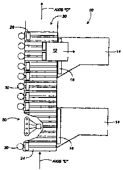
Fig. 1 is a top view of a conveyor system 10 according
to the present invention used in conjunction with a discharge
station according to the present invention. No retractors are
shown.
Fig. 2 is a side cross sectional view of the conveyor
system 10 according to the present invention viewed along the
conveying axis. No retractor is shown.
CA 02282451 1999-08-24
WO 98/38118 PCT/US98/03326
9
Fig. 3 is a side isolated view of a first discharge station
SO according the present invention, viewed from the side of
the conveyor across the conveying axis.
Fig. 4 is a detailed view of a portion of the package
conveying portion, including a retractor 28.
Fig. 5 is an isolated view of a floating detachable power
connection between an air supply nozzle 62 and an air receptor
31 according to the present invention.
Fig. 6 is an isolated view of a mufti-connection electrical
commutator according to the present invention in use with the
inflated endless tube according to the present invention.
Fig. 7 is a partial cross-sectional view of an inflated
endless tube 60 according to the present invention, having a
cog belt 63 attached thereto. A guide sheave 66 is also shown
without a drive sprocket therein.
Fig. 8 is a side isolated view of a second discharge
station 150 according to a second embodiment of the present
invention, viewed perpendicular to and across the conveyor
axes.
Fig. 9 is a side isolated partial cross-sectional view of
the second discharge station 150 according to the present
invention, viewed along the conveying axis of the conveyor,
and showing a rotating air chamber in cross section.
Fig. 10 is an isolated view of a mufti-contact electrical
commutator according to the present invention which can be
used to provide electrical supply to any of the embodiments
requiring electrical signals or power along an endless path.
Fig. 11 is a side isolated view of a third discharge station
according to a third embodiment of the present invention,
viewed from the side of the conveyor.
Fig. 12 is view of a vertical bellows configuration
capable for use with a fourth embodiment of the present
invention supplied with air from an air supply nozzle 62, 102.
CA 02282451 1999-08-24
WO 98/38118 PCT/US98/03326
Fig. 13 is view of the horizontal bellows configuration
capable for use with the present invention as a lateral urging
assembly.
Fig. 14 shows a lead screw configuration 290 capable
5 for use with the present invention as a lateral urging assembly.
Fig. 15 shows another view, an isolated pictorial view,
of the lateral urging assembly 23 translator shoe 26 atop the
shoe carrier 24, which conceals the endless belt 34 driven by
the air motor 30.
Detailed Description of the Preferred Embodiment
Reference is now made to the figures, in which like
numerals represent like elements throughout the written
description.
Overview
Generally described, the present invention relates to the
provision of a package conveyor which operates in conjunction
with a discharge station, with the discharge station providing
power to the conveyor sufficient to discharge packages
laterally from the conveyor by means of lateral translation
assemblies which can take various forms. Moving parts on the
stationary discharge station are synchronized with the
conveyor such that a plurality of intermittent, "floating",
power connections or "power interfaces" are provided between
the discharge station and the conveyor. These connections
allow for power to be transferred from a substantially
stationary off-conveyor source to the lateral translation
assemblies moving along with the conveyor.
The "floating" power connections can be electrical, air,
or other means known in the art. In the case of an air
connection, a plurality of air-supplying "nozzles" are provided
to move on an endless track. Each nozzle is supplied with air
and is configured for synchronous engagement with a suitable
CA 02282451 1999-08-24
WO 98/38118 PCT/US98/03326
11
receptacle on an air motor which is attached to the conveyor.
Air supplied to the air motors can provide sufficient power to
provide a pushing motion sufficient to discharge packages
sidewardly, even as the conveyor is moving. Air is supplied to
the nozzles through means such as an "inner tube" or a number
of individual air supply tubes attached to a common air supply
housing. The air supply to each nozzle is controlled by air
valves themselves controlled by, for example, a programmable
logic controller, which allows for improved control of the
transverse movement of translator shoes attached to the
conveyor.
In the case of a floating electrical connection, a pair of
exposed electrical connections are provided in place of each of
the nozzles and receptacles. Again, the electrical current
supply to each nozzle is controlled by a programmable logic
controller.
The lateral translation assemblies can take the form of a
translator shoe slidably mounted on the conveyor and driven
by an endless belt or a lead screw, either of which can be
driven by an air or electric motor. Horizontal or vertical
bellows may also be used to provide a pushing or tilting action,
respectively.
First Embodiment
Referring now first to Fig. 1, packages 12 are
discharged from atop a conveyor 20 by the use of a plurality
of lateral urging assemblies 23 (also known as "pusher
assemblies"), each of which includes at least one translator
shoe 26 (which may also be referred to as a "pusher plate").
The translator shoes 26 are configured to push packages
positioned atop the upwardly-directed surface of the conveyor
20 off of the conveyor in a direction generally transverse to
the travel axis of the conveyor axis, which is generally up-and
down as viewed in Fig. 1, and substantially normal to the
drawing plane of Fig. 2.
CA 02282451 1999-08-24
WO 98/38118 PCT/US98/03326
12
The discharge stations, generally denoted as 50 in Figs.
1 and 2, are positioned under one edge of the conveyor 20, and
are configured to cause selected movement of the translator
shoes 26 when they are in the vicinity of the discharge station
50. Each discharge station 50 has a corresponding discharge
chute 14 configured to receive the packages 12 as they are
pushed laterally from the conveyor 20. An elongate exit roller
I6 (See Fig. 1 only) is provided at the mouth of each discharge
chute to facilitate movement of the packages into the discharge
chute 14. The exit roller 16 is rotatably mounted about an axis
which is substantially parallel to the conveyor axis C
As shown in Fig. 2, each lateral urging assembly 23
attached to the flexible conveyor belt 22 includes a translator
shoe 26, shoe carrier 24, air-driven motor 30, cog belt 34,
drive sprocket 32 and idler sprocket 33.
Each translator shoe 26 is slidably mounted atop a shoe
carrier 24 which is itself mounted to the belt 22. The shoe
carrier 24 also acts as a containment shield for the cog belt 34.
The cog belt 34 is endless, and is supported by the drive
sprocket 32 and the idler sprocket 33. The cog belt 34 is
driven by the drive sprocket 32, which is itself driven by an
air motor 30. The air motor 30 is reversible, and is controlled
by an off-conveyor programmable logic controller (PLC) to
provide the back and forth movement of the translator shoe.
As noted above, the air motors 30 are attached to the
conveyor belt 22, and therefore each move along with the
conveyor belt 22. As the conveyor belt 22 is in the preferred
embodiment endless, it moves along an endless path. The
present invention provide an intermittent, temporary supply of
air power at certain "stations" along this endless path by the
use of discharge stations 50 such as shown in Figs. 1-7. Each
of these discharge stations 50 supplies air to at least one of the
air motors 30 as they pass by the discharge stations 50. This is
done by providing air nozzles for movement along an endless
path configured to engage suitable receptacles on the air
CA 02282451 1999-08-24
WO 98/38118 PCT/US98/03326
13
motors, to provide the air motors with air as needed. The
discharge stations each include a flexible endless tube 60
(which can be considered to as an "inner tube"), air nozzles 62
attached to the endless tube, a cog belt 63 attached to the
endless tube, a tube drive motor 52 and associated drive
elements, and associated air and electrical current supply
elements.
Generally described, as shown in Figs. 1-7, air supplied
from an outside source is provided into the flexible tube 60
and passes from air nozzles 62 attached thereto into receptacles
31 on the air motors 30. Movement of the air motors 30 and
the air nozzles 62 is synchronized. Air valuing is discussed
below further detail.
Referring now to Figs. 2, 3, 6, and 7, the inflated
endless tube 60 is rotated about a plurality of pulleys on a cog
belt 62 that is attached to the inner side of the inflated endless
tube 60.
As shown especially well in Fig. 6, the cog belt 63 is
driven by a drive motor 52 though means of a drive shaft 53
attached to a drive sprocket 54. The drive sprocket has edge
guides to provide guidance to the endless tube 60. In the
embodiment shown, the rotational axis of the drive shaft 52
and drive pulley 54 is substantially horizontal, below the plane
of the conveyor, and substantially transverse to the travel axis
C of the conveyor.
As shown in Fig. 2, air is supplied to the inflated endless
tube 60 by a rotary coupling 72 which connects a rotating air
line 73 with a substantially stationary air line 70 which
supplies air from an air source (not shown) to the endless air
filled tube 60.
The flexible air line 73 must flex in the embodiment
shown in Fig. 6, as one end attached to the rotary air
connector $2 will be following a substantially circular route,
while its opposite, "outer" end (attached to the inner tube) will
be following a noncircular route. In the embodiment shown,
CA 02282451 1999-08-24
WO 98/38118 PCT/US98/03326
14
the route will approximate a substantially oval path comprised
of two straight lengths alternating with cofacing semicircular
segments.
As shown in Fig. 7, a solenoid valve 64 is located inside
the inflated endless tube 60 at each of the air jets and is
electronically controlled to provide air from within the tube
60 to a given nozzle 62 as desired. The air pressure inside the
inflated endless tube 60 is maintained at approximately 50-100
psi and is supplied via an external air valve, as seen in Fig. 7.
The solenoid valves 64 are electronically controlled by
an electrical power controller which is, in turn, controlled by
a programmable logic controller (not shown).
Operation of the first embodiment of the present
invention is as follows. As the conveyor belt is energized, the
inflated endless tube 60 assembly is likewise energized so that
the conveyor belt and the inflated endless tube 60 travel in the
same direction, at the same synchronized speed. While in
motion, the air intake receptors of the air motors attached to
each parcel ejection mechanism engage the air nozzles 62 in
the inflated endless tube 60 at each discharge station as the air
motors 30 travel by. With this configuration, the air motors
of the parcel ejection mechanisms will always engage the
air distribution system when the parcel ejection mechanisms
are laterally adjacent to a given discharge station, as seen in
25 Fig. 1. Actuation of an air motor is feasible only when a
particular air nozzle 62 engages the air receptacle 31 of the air
motor and opens in response to a signal from the
programmable logic controller, as shown in Figs. 2 and 3. Air
is thus released from the inflated endless tube 60 through the
30 air nozzle, through the air receptacle, and to the air motor to
actuate the motor and ultimately the parcel ejection mechanism
as shown in Fig. 2. Retraction of the translator shoe 26 of the
parcel ejection mechanism takes place after the programmable
logic controller closes the air valve and allows the coil spring
CA 02282451 1999-08-24
WO 98/38118 PCT/US98/03326
retractor to bring the translator shoe 26 back to its original
position, as shown in Fig. 2.
Second Embodiment
5 Figs. 8 and 9 illustrate a second embodiment of the
present invention. In this embodiment, a plurality of air
nozzles 162 are attached to a sprocket-driven cog belt 163. As
shown in Fig. 8, the sprocket-driven belt 163 is disposed such
that the air nozzles 162 will engage the air intake receptors
10 attached to the air motors of each parcel ejection mechanism,
in a manner similar to the engagement of the nozzles 62
discussed in conjunction with the first embodiment.
As shown in Fig. 9, air is supplied to the air nozzles 162
by a rotating air chamber 171 which is operatively connected
15 to the air nozzles 162 by a plurality of flexible air lines 173.
A rotary coupling 172 is provided which allows the rotating
air chamber 171 to receive air from a fixed air supply line
170.
Within each flexible air line 173 is an electrically-
controlled air valve 164, which is supplied with suitable
current via corresponding electrical wires 183, and again
controllable with a PLC.
The rotating air chamber 171 shown in Fig. 9 is rigidly
attached relative to an air chamber drive sprocket 174. This
sprocket 174 is driven as shown in Fig. 8 by a cog belt 175
which is also linked to a sprocket driving or driven by the cog
belt 163. This allows for synchronization of the two belts 175,
163 and for their associated sprockets.
The flexible air lines 173 must flex in the embodiment
shown in Fig. 9, as their ends attached to the rotating air
chamber 185 will be following a substantially circular route,
while their opposite ends (attached to the air nozzles 162) will
be following a noncircular route. In the embodiment shown,
the route will approximate a substantially oval path comprised
CA 02282451 1999-08-24
WO 98/38118 PCT/US98/03326
16
of two straight lengths alternating with cofacing semicircular
segments.
Referring now to Fig. 10, a rotary commutator 82, 182
is provided to accommodate the rotation of the electrical wires
83, 183 of the corresponding two embodiments described
above along with the rotating air cylinder 183. The electrical
wires 183 are electrically connected to a commutator having a
plurality of ring-shaped contacts, which are configured to
slidingly contact stationary contacts which lead to a
programmable logic controller (not shown).
The air distribution system of the second embodiment
likewise travels with the overlying conveyor system such that
the belt mounted air nozzles engage the air receptors of the air
motors as the parcel ejection mechanisms travel by on the
overlying conveyor system. Referring to Fig. 9, the air motor
is actuated by a release of air from the rotating air chamber.
The operation of the electric air valves again may be
controlled by a programmable logic controller.
Third Embodiment
In the third embodiment shown in Fig. 11, electric
motors 230 may be used in place of air motors. In this case,
power via electricity will be distributed to the electric motors
in a manner similar to the second embodiment, described
above, by mounting electrical contacts 262 onto a cog belt 263
rather than air nozzles. The electrical contacts will engage
corresponding electrical contacts on the electric motors 230,
similar to the engagement of the air nozzles with the air intake
receptors of the air motors. An electrical commutator
3o assembly similar to that shown in Fig. 10 can be used, except
that the electrical wires will lead to the contacts 262 mounted
to the belt 263 instead of to a valve.
CA 02282451 1999-08-24
WO 98/38118 PCT/US98/03326
17
Fourth Embodiment
Reference is now made to Fig. 12, which shows a lateral
urging assembly taking the form of a vertical bellows
configuration 270 including vertical air bellows members 271,
a tiltable tray 272, and a conveyor belt 273. The tiltable tray
such as 271 is supported by the vertical bellows members 272,
which can be used such that a package "P" placed stop the tray
272 slides off at least partly under the influence of gravity
upon tilting of the tray by the bellows. The conveyor belt 273
(which in one preferred embodiment is of conventional
flexible conveyor belt material) defines bellows ports 274,
which facilitate air passage therethrough to corresponding
bellows 271 to cause their inflation as illustrated. Such a port
274 allows for air to pass therethrough, such that air blown
through the port under a relatively low pressure facilitates
inflation and expansion of its associated bellow member,
causing the tray to be moved upwardly. Assuming that only
one bellows is inflated, this causes the tray 272 to tilt, thus
allowing for lateral sliding movement of a package from atop
the tray off the conveyor at least partially under the influence
of gravity.
It should be understood that the air supply nozzle 62,
162, shown in Fig. 12 can be such as that included as 62 in the
first embodiment of the present invention which includes an
endless air tube, or may be such as 162 in the second
embodiment of the present invention which includes an endless
belt supporting the air supply nozzles 162 thereon.
Fifth Embodiment
Another particular type of lateral urging assembly
generally denoted as 280 in Fig. 13 can be a "push plate"
conveying segment. In this embodiment, two or more
horizontally-acting bellows members 281 are attached relative
to the top surface of a conveyor belt 273, to provide a pushing
CA 02282451 1999-08-24
WO 98/38118 PCT/US98/03326
1$
function to a package situated atop the top surface of conveyor
belt 273, such that it is pushed off the conveyor belt 273.
The configuration 280 includes a base 282 a chamber
housing 285, bellows members 281, and a push plate 282. The
air chamber housing 285 is attached to the upper surface of the
conveyor belt 273. The air chamber housing 285 defines an
interior air chamber which is supplied air through a chamber
inlet port 286 and itself supplies air to one or more chamber
outlet ports 287, depending on the number of bellows
members used. Each of the chamber outlet ports 287 supplies
air from the chamber to a corresponding horizontally-oriented
bellows 281.
It should be understood that the air supply nozzle 62,
162, shown in Fig. 12 can be such as that included as 62 in the
first embodiment of the present invention which includes an
endless air tube, or may be such as 162 in the second
embodiment of the present invention which includes an endless
belt supporting the air supply nozzles 162 thereon.
It should be also noted that the invention contemplates
the use of dual, side-by-side, horizontal bellows, which can be
controlled by the PLC to allow for a single pusher member to
be "angled', if desired, to facilitate angled discharge if so
desired. This can be done by controlling the relative flow of
air into the two adjacent bellows members.
Sixth Embodiment
Still other lateral urging assemblies could be used. Fig.
14 shows a lateral urging assembly taking the form of a lead
screw configuration 290. A lead screw 291 is powered by an
electric gear motor 292, such that a translator shoe 293 can
move across a slotted platform 294. One end of the rotatable
lead screw is held and driven by the motor 292 and the other
end is rotatable mounted relative to the platform 294 by a
bearing 295. Electrical leads 296 are exposed which can be
connected as described above to provide a "floating" power
CA 02282451 1999-08-24
WO 98/38118 PCT/US98/03326
19
connection to the motor 292. The platform is connected to
other rigid platforms by an intermediate flexible or pivotable
connection (not shown), or can be mounted atop a flexible belt
if so desired. An air motor could also be used.
Alternatives
As shown in Fig. 1, a discharge chute 14 is shown to
accept packages as they exit the conveyor 20 sidewardly.
However, it should also be understood that other means could
be provided to accept said packages. For example, a second
conveyor could be provided to accept and further convey the
packages, or an stationary bin or sack could be used.
Conclusion
~ 5 While this invention has been described in specific detail
with reference to the disclosed embodiments, it will be
understood that many variations and modifications may be
effected within the spirit and scope of the invention as
described in the appended claims.