Note: Descriptions are shown in the official language in which they were submitted.
CA 02282587 1999-08-26
WO 98/38528 PCT/US98/04075
CONDENSATE FREE ULTRASONIC TRANSMITTER
Field of the Invention
The present invention relates generally to ultrasonic systems for measuring
distance.
Background of the Invention
In the most common ultrasonic distance measuring system, a single
piezoelectric crystal is used both as a transmitter of ultrasonic pulses and
as a receiver of
the return echo from the surface whose distance is to be measured. A short
pulse, typically
100 micro-seconds duration, of ac voltage of an appropriate frequency is
applied to the
piezoelectric crystal. The crystal vibrates, and transmits an ultrasonic pulse
into the
medium separating the ultrasonic transducer from the surface whose distance is
to be
measured. The echo reflected from the surface causes the crystal to vibrate
and produce
an electrical voltage between its faces of the same frequency and of an
amplitude
proportional to the strength of the echo.
The time between the start of the transmitter pulse and the received pulse is
measured (corrected for temperature of the medium) to determine the distance.
The
crystal is supplied with dampening such that its vibration will be negligible
by the time the
return echo is received.
As shown in Figure 1, an ultrasonic level measuring system may comprise
an ultrasonic transducer 10 coupled to a housing 20 containing control
circuitry and a head
temperature sensor 30. In addition, in this example, the transducer 10 is
attached to a head
40 (at a temperature Tr, ) by a threaded neck region 12, and is disposed
within a cylindrical
neck 50 extending from a wall of the container for the substance 60 (granular}
or 70
CA 02282587 1999-08-26
WO 98/38528 PCT/US98/04075
-2-
(liquid) whose surface level is to be measured. As shown, the transducer 10
has a front
surface 14 at a temperature designated Ts.
The process material temperature (TM) is typically higher than the head
temperature (TH). The transducer surface temperature (Ts) will consequently be
very close
to the head temperature and may be cooler than the dew point of the air around
it. This
condition may produce condensation on the transducer surface, and the
condensation will
interfere with the measuring function. Condensation will cause absorption,
reflection and
scattering of the transmitted energy, reducing the energy transmitted to the
material. In
addition, the surface condensation will cause reflection of the energy
reflected (or echo)
from the material surface. In many cases, these effects will be su~cient to
prevent
sensing of the material level. If the surface temperature TS is below
32°F, the condensate
will freeze as it forms and successive layers of ice will still further limit
the transducer
function.
Accordingly, there is a need in the ultrasonic distance/level measuring art
for a system and method for preventing condensation from interfering with the
correct
operation of the measuring system.
Summary of the Invention
The present invention combines a heater under the transducer surface and a
control circuit that causes heat to be added to the surface as required to
maintain the
surface temperature at a desired value (selected value) sufficient to prevent
condensation
independent of the head temperature (T,,). A distance or level measuring
system in
accordance with the present invention is employed to measure the distance
between a
predetermined location and a material having a surface (as discussed above).
The
inventive system comprises a transducer ( 10), heater means ( 18) for heating
the transducer
so as to prevent the formation of condensation in an area adjacent the
transducer and
between the transducer and the material surface, and an electrical control
circuit (80, 80')
coupled to the heater means for controllably energizing the heater means. In
presently
preferred embodiments of the invention, the power supplied to the heater by
the control
circuit supplies is proportional to the degree to which the head temperature
is less than the
target surface temperature.
,. . .
CA 02282587 1999-08-26
WO 98/38528 PCT/US98/04075
-3-
In presently preferred embodiments of the invention, the transducer is an
ultrasonic transducer for controllably transmitting acoustic pulses toward the
material
surface and receiving return acoustic pulses reflected from the material
surface. The
distance between the transducer and the material surface may be determined in
accordance
with well known techniques (which are not described herein).
In addition, in the presently preferred embodiments, the heater means
comprises an electrical resistor disposed over a supporting substrate.
Further, the system
also includes an impedance matching layer situated as disclosed below between
the
transducer and the material surface, and the heater means is disposed adjacent
to the
impedance matching layer. The impedance matching layer is preferably
characterized by
a thickness, measured in a direction of acoustic energy propagation from the
transducer, of
approximately one-quarter wavelength at a predetermined operating frequency.
The system may also include a safety burner situated between the
transducer and the material surface, and the heater means may be disposed
adjacent to the
safety barrier. The safety barrier may have a thickness, again measured in a
direction of
acoustic energy propagation from the transducer, of approximately one-quarter
wavelength
at the operating frequency.
In addition, the presently preferred embodiments of the invention include a
layer of acoustic couplant disposed between the transducer and the material
surface. For
example, the acoustic couplant may be situated between the impedance matching
layer and
the material surface, or between the safety barrier and the transducer. The
heater means is
preferably embedded in the safety burner but may alternatively be situated on
a surface of
the safety barrier. The safety barrier thus performs the function of the
matching layer.
Another aspect of the present invention is an electrical control circuit for
use in supplying power to a heater. The inventive control circuit includes
means for
receiving as a first input a signal indicative of a target temperature and as
a second input a
signal indicative of a measured temperature, and means for suppling power to
the heater
proportional to the degree to which the measured temperature is less than the
target
temperature.
Other features of presently preferred embodiments of the invention are
disclosed below.
CA 02282587 1999-08-26
WO 98/38528 PCT/US98/04075
-4-
Brief Description of the Drawings
Figure 1 schematically depicts an ultrasonic distance or level measuring
system.
Figure 2 schematically depicts, in partial section, an ultrasonic transducer
in accordance with the present invention.
Figure 3 schematically depicts front cross-sectional and side views of a
heater for an ultrasonic transducer in accordance with the present invention.
Figure 4 schematically depicts a first embodiment of an electrical heater
circuit in accordance with the present invention.
Figure 5 schematically depicts a second embodiment of an electrical heater
circuit in accordance with the present invention.
Figure 6 schematically depicts in more detail the embodiment of the
electrical heater circuit of Figure 4.
Figure 6' schematically depicts in more detail the embodiment of the
electrical heater circuit shown in Figure 5.
Figure 6A schematically depicts a power supply circuit for use in an
ultrasonic distance or level measuring system in accordance with the present
invention.
Figure 6B is a schematic diagram used to explain the operation of the
heater control circuit.
Figure 6C is a waveform diagram used to explain the operation of the
heater control circuit of Figure 6.
Figure 6D is a graph of the temperature coefficient of nickel 270, a material
useful for making a temperature sensing heater of the kind used in the
embodiments of
Figures 5 and 6'.
Figure 6E is a waveform diagram used to explain the operation of the
heater control circuit of Figure 6'.
Figure 7 is an assembly diagram, in cross section, of a "non-intrusive"
ultrasonic distance or level measuring system in accordance with the present
invention. In
this configuration, a piezo transmitter/receiver is not cemented to a safety
barrier but is
held in tight contact with it and the joint is filled with acoustic "gel."
Figure 7A is a partial cross-sectional view of the ultrasonic transducer in
Figure 7.
~ ~.
CA 02282587 1999-08-26
WO 98/38528 PCT/US98/04075
-5-
Figure 8 is a view of the portion of the transducer including a one-half
wavelength barrier and a one-quarter wavelength impedance matching layer. In
this
embodiment, the impedance matching layer is cemented to the crystal.
Figure 8A depicts a configuration of the transducer in which the transducer
is pressed against a half wavelength barner and the joint is sealed with
acoustic couplant.
Figure 9 depicts an embodiment of the half wavelength barrier with an
embedded heater.
Figure 10 depicts an embodiment of the one-half wavelength barrier with a
separate heater.
Detailed Description of Preferred Embodiments
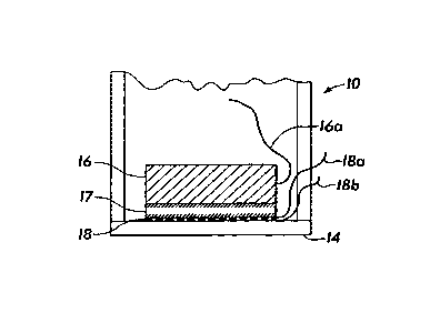
The heater location is shown in Figure 2. It is a thin layer I 8 cemented
between the acoustic impedance matching layer 17 and the transducer face 14.
The
ultrasonic crystal 16 is also shown, as are the wire leads 16a, 18a, 18b for
energizing the
crystal 16, and heater I8, respectively.
Construction of the heater 18 is shown in Figure 3. As show, the heater
comprises a very thin metallic resistor having a serpentine shape and being
supported on
either side with suitable plastic films 18c and 18d. The resistor can be made
of a flat metal
ribbon. Both the metal and the plastic layers are thin enough so as not to
interfere with the
acoustic energy transmission.
A first embodiment of a heater circuit is shown in Figure 4. This
embodiment comprises a head temperature (T") sensor 30, a control circuit 80,
and a
switching transistor 90 operatively coupled as shown to the heater element 18.
Thus, the
heater 18 and transistor 90 are connected in series across a 12V power supply
and ground.
The control circuit 80 receives as inputs the measured head temperature T" and
the target
surface temperature, and adjusts the heater current by appropriately setting
the conduction
time of the transistor 90. In other words, the control circuit is supplied a
voltage
proportional to the desired surface temperature (target surface temperature).
Also supplied
to the control circuit is a voltage from the head temperature sensor. The
control circuit
supplies power to the heater proportional to the degree to which the head
temperature is
less than the target surface temperature.
CA 02282587 1999-08-26
WO 98/38528 PCT/US98/04075
-6-
Table 1 shows exemplary results for a situation where the target
temperature is 100°F. When the head temperature is equal to or greater
than the target
temperature, no added heat is required to maintain the target temperature. As
the head
temperature drops below the target temperature value, the heat is supplied
proportional to
the difference in temperature.
TABLE 1
Target Head Required Required Surface
Tem Tem Tem Rise Power Tem
Ti HT Ts
100F 100F 0F 0 100F
100F 45F 55F 1 W 100F
-100F -10F 110F 2 Watts 100F
The rate for the transducer in Table 1 was determined to be 0.018
watt/°F.
In another example, the material temperature may be up to 180°F
and the
head temperature may vary from 70°F to 100°F. When the target
temperature is selected to
be 180°, the results are as shown in Table 2. Again, the surface will
be maintained at a
value which will prevent condensation.
TABLE 2
Target Head Required Required Surface
Tem Tem Tem Rise Power Tem
108F 100F 70F 1.26 Watts 180F
180F 100F 80F 1.44 Watts 180F
-70F 110F 2 Watts
An alternative method to control the heater is to use the heater itself as a
temperature sensitive resistor as shown in Figure 5. In this approach, the
heater is
included as one leg of a resistance bridge, which includes a control circuit
80' and a
differential amplifier 92 in addition to the switching transistor 90 and 12V
power supply.
Current supplied to the bridge causes an increase in the heater temperature.
The current
continues to increase until it reaches the target value at which the bridge is
balanced and
no further increase in current takes place. Thus, the heater is maintained at
the target
~.
CA 02282587 1999-08-26
WO 98/38528 PCTIUS98l04075
_ '7 _
temperature, and as the surface is closely coupled to it, the surface
temperature is
maintained very close to the target temperature.
The control circuit 80, 80' is depicted in greater detail in Figures 6 and 6A,
and in Figure 6'.
In Figure 6, the control unit comprises four basic functional sections:
1. Temperature Sensor
2. Ramp Generator
3. Comparator U, connections 5, 6 and 7
4. Field Effect Switching Transistor (with low "on" resistance)
The temperature sensor is mounted to respond to the head temperature (TH)
and produces a voltage proportional to the head temperature.
The Ramp Generator produces a triangular voltage which has a maximum
value equal to the output of the temperature sensor when the temperature is
equal to the
target temperature for the surface temperature TS.
The minimum voltage from the Ramp Generator is made equal to the head
temperature (TH) at which maximum power is required.
The voltage from the temperature sensor is connected to one input (#6) of
the comparator, while the triangular voltage from the Ramp Generator is
connected to the
other input (#5) of the comparator.
2C) When the voltage from the Ramp Generator is greater than the temperature
sensor voltage, the control switch Ql is closed, applying power to the heater.
Figure 6C
shows this action.
Potentiometer R6 adjusts the Ramp Generator output corresponding to the
target temperature.
Resistor R4 is selected to set the value of the Ramp Generator voltage
corresponding to the temperature for full power.
In some cases, as described, it is sometimes necessary to heat the transducer
face by a considerable degree, and maximum efficiency is required to reduce
the energy
required. By limiting the heating to just the exposed face, a maximum
temperature rise for
minimum energy is achieved. In a preferred embodiment of this invention, the
heating
element is located immediately behind the transducer surface and is uniformly
distributed
across the entire surface. By locating the heater and connection entirely
within the
CA 02282587 1999-08-26
WO 98/38528 PCTIUS98104075
_g_
transducer body, they are not exposed to the atmosphere around the transducer
and thus
will not constitute a hazard when the transducer is used in a flammable
medium.
In many cases, such as uses involving pharmaceuticals, it is essential to be
able to check and/or replace the transducer without opening the vessel, which
could
contaminate the contents. This is accomplished as shown in Figures 7 and 7A.
A safety barrier is sealed to a nozzle on the vessel while the transducer is
outside of the vessel and measuring through the safety barrier. The safety
barrier
thickness is selected to constitute, along with the transducer face, 1 /4-
wavelength at the
operating frequency. Thus, the barrier and transducer face provide an
impedance match
between the piezoelectric crystal and the air or gas within the vessel.
In the embodiment shown in Figure 6', the heater is made of a material
having a known, nonzero temperature coefficient of resistance (such as nickel
270). A
switching transistor Q3 is selected to have an "on resistance" which is small
compared to
the resistance of the heater. For example, a heater having a resistance of 70
Ohms at 75 °F
rising to 98.36 Ohms at 200 °F can be used with a switching transistor
such as an
MTP3055E, having a typical "on resistance" of 0.05 Ohm. The resistance of the
heater
(R" in Fig. 5) is included in a Wheatstone bridge with resistors (Rl, R2, and
R5 in Fig. 5)
respectively including (R16, R20, and Rprogl in parallel), (R19 and Rprog2 in
parallel), and
R21. R16 and R20 are chosen such that their parallel resistance will be equal
to 187 times
the resistance of the heater about 8 °F below the target temperature.
(This is
approximately the temperature at which full power is applied to the heater.)
The resistor
selected for R16 is chosen from a chart based on measurements of the actual
resistance of
the heater and R20, thus compensating for variations in their resistances due
to
manufacturing tolerance. R21 is chosen to be small compared to the resistance
of the
heater, to avoid wasting power in it, but is large enough to produce
sufficient voltage to
enable accurate control of the temperature of the heater.
A substantially triangular wave varying between 1.1 volts and 6.1 volts and
having a period of approximately 12 seconds is generated on capacitor Cl by
comparator
UIA. At the positive peak of the wave, the (substantially rectangular) output
of UlA
switches from approximately 11 Volts to a voltage near ground. The negative
transition of
this voltage is differentiated by C3, R8 and R9, and applied to the base of
Ql, which turns
off for approximately 120 milliseconds. R10, acting through D2, develops
approximately
CA 02282587 1999-08-26
WO 98138528 PCTIUS98/04075
-9-
volts across R13 and the gate of Q3, forcing Q3 to turn on for 120
milliseconds during
each control cycle, regardless of the heater temperature. Simultaneously, R11
begins
charging C5, raising the voltage at the gate of Q2. After approximately 2
milliseconds, Q2
turns on, connecting the "error voltage" of the Wheatstone bridge to U2A,
which amplifies
5 it by approximately 2000 (the ratio of R7 to R17). The timing of the control
waves is
illustrated in Figure 6E.
Still referring to Figure 6', the output of U2A is stored on C4 during the
time Q2 is turned off (there is a small decay due to the bias current of U2A
discharging C4
but this has a negligible effect on the control). After 120 milliseconds. Q1
turns back on,
10 discharging CS through Dl, and thus turning off Q2, and allowing Q3 to be
controlled by
U1B (if the temperature of the heater were substantially higher than the
target temperature,
Q3 would tum off at this time).
The voltage at the output of U2A is compared to the triangle wave by
comparator U1B. If the output of U2A is lower than the triangle wave, R6 pulls
up the
output of U 1 B. This is coupled through diode D3 to R13 and the gate of
transistor Q3,
raising it to approximately 10 Volts and turning on the transistor. The
conduction time of
Q3 varies substantially linearly with the temperature of the heater, from a
minimum of
about 120 milliseconds to the full cycle time.
U2B, D4, R12, RI 4 and Rl 5 prevent thermal runaway if the connection to
Rl6 and R20 is lost. R14 and R15 develop a voltage of approximately 72
millivolts at the
positive input to U28. The voltage at the junction of R16, R19 and R20 (the
reference side
of the Wheatstone bridge) is applied to the negative input. If the connection
to RI 6 and
R20 is lost, the output of U2B goes high and forces the voltage at the
negative input of
U1B high through diode D4. This limits the conduction of Q3 to the 120
millisecond
minimum established by Q1.
As shown in Figure 7, the piezo transmitter/receiver is not cemented to the
barner but is held in tight contact with it and the joint is filled with an
acoustic couplant
compound (such as, e.g., acoustic grease, silicone oil, or other material that
conducts
acoustic energy well).
An alternate configuration is shown in Figure 8. In this case an impedance
matching layer with 1/4-wavelength thickness is cemented to the crystal. The
matching
CA 02282587 1999-08-26
WO 98/38528 PCT/LJS98/04075
- 10-
layer is held against the barrier and the joint is sealed with acoustic
couplant. In this case,
the barner is one-half wavelength in thickness.
The system shown in Figure 8A has also been demonstrated. In this
configuration, a standard transducer was pressed against the half wavelength
barner and
S the joint was sealed with acoustic couplant.
In the standard transducer, the crystal was cemented to the impedance
matching layer, which in turn was cemented to a 0.030 inch thick face. In this
case, the
face plate was CPVC.
The face of the barrier toward the process can, if cooler than the dew point
in the vessel, collect condensation interfering with the operation. In this
case, a heater
described earlier is in the preferred form embedded in the barrier near the
process face, as
shown in Figure 9. In this form, the layer supporting the thin metallic heater
should be of
the same material as the barrier.
In an alternatives approach, which will function but much less effectively,
the heater can be cemented to the outside of the barner as shown in Figure 10.
When the
barner is required to tolerate greater pressure, the barrier thickness is
selected to produce
the 1 and 1/4 wavelengths along with the transducer face. Any air space
between the
transducer face and the safety barrier will substantially reduce the energy
transmitted in
the vessel and further reduce the echo reaching the transducer. To prevent
this, the space
between the transducer face and the safey barrier is filled with acoustic
couplant, and an
"O" Ring prevents the couplant from bleeding out or drying.
Experience has shown that some difficulty may be experienced from
acoustic energy being transmitted into the vessel nozzle 50 with resulting
resonance. The
resonance can be eliminated by clamping rubber or other acoustic absorbing
material to
the outside of the nozzle.
The scope of protection of the following claims is not intended to be
limited to the specific presently preferred embodiments of the invention
disclosed above.
Those skilled in the art will recognize that variations and modifications may
be made to
the above-described embodiments without departing from the true spirit of the
invention.
,.~_..