Note: Descriptions are shown in the official language in which they were submitted.
CA 02283007 1999-09-22
TITLE OF THE INVENTION:
Containment Structure and Method of Manufacture Thereo~
NAME(S) OF INVENTOR(S):
P. John Fitzpatrick
David G. Stenning
James A. Cran
FIELD OF THE INVENTION:
This invention relates to containment structures and methods of manufacture
thereof, particularly for the marine transport and storage of compressed
natural gases.
BACKGROUND OF THE INVENTION:
The invention relates particularly to the marine gas transportation of
compressed
gas. Because of the complexity of existing marine gas transportation systems
significant
expenses are ensued which render many projects uneconomic. Thus there is an
ongoing
need to define storage systems for compressed gas that can contain large
quantities of
compressed gas, simplify the system of complex manifolds and valves, and also
reduce
construction costs. This specific system, which is a unique development of the
more
general systems described in the above patent application, purports to do all
three.
SUMMARY OF THE INVENTION:
In an aspect of the invention, there is provided a containment structure
comprising
a continuous coiled pipe formed in at least a first layer and a second layer
lying on top of
the first layer, coiled pipe in the second layer lying directly on top of and
aligned with the
coiled pipe in the first layer, apart from a first transition zone in which
coiled pipe in the
first layer rises to form part of the second layer and cross coiled pipe in
the first layer.
In a further aspect of the invention, there is provided a method of forming a
containment structure, comprising forming a continuous coiled pipe in at least
a first
layer and a second layer lying on top of the first layer, with coiled pipe in
the second
layer lying directly on top of and aligned with the coiled pipe in the first
layer, apart from
CA 02283007 1999-09-22
2
a first transition zone in which coiled pipe in the first layer rises to form
part of the
second layer and cross coiled pipe in the first layer.
In a further aspect of the invention, there is provided a containment
structure
comprising a continuous constant diameter coiled pipe formed in a single layer
of
alternating constant radius circle segments, in which each circle segment
covers 360/n
degrees, with each succeeding circle segment being 1/n pipe diameters greater
in radius
than a preceding circle segment, where n is greater than 1.
The containment structure of the invention is particularly suited for use as a
gas
storage system, particularly adapted for the transportation of large
quantities of
compressed gas on board a ship (within its holds, within secondary containers)
or on
board a simple barge (above or below its deck, within secondary containers).
The coiled
pipe is preferably formed of long, primarily circularly curved sections of
small diameter
steel pipe. The pipe, generally smaller than 8 inches may be coiled in a
specific manner
within a simple circular container.
In one embodiment, the diameter of the container is about 50 feet and it is
about
10 feet high. Approximately 10 miles of pipe or more may be coiled and stacked
within
the container. The coiling is continuous and there are no valves or
interruptions from the
start to the end of the coil.
In one aspect of the invention, the pipe may be viewed as starting at the
inside of
the bottom layer. It spirals outwards by means of constant curvature constant
radius
segments, preferably semi-circles, which abruptly change their curvature and
also their
centers of curvature by a small percentage of their gross curvature and their
radii
respectively. By this means programming and quality control on the bending
rollers are
kept constant and simple for relatively long periods of time. When the pipe
reaches the
outside of the container it is forced by the geometry of the container to
climb up to the
second layer and then start an inwards spiral. After two semi-circular arcs
the pipe
follows a transition curve which takes it across two pipes immediately below,
in a
distance of about 12 pipe s. This distance is relatively short and thus
vertical stacking
stresses at crossover points are minimized. By transitioning two pipes beneath
and then
by spiraling back out one of the pipe, immediately above the first and
subsequent odd
layers, a net inwards spiral gain of one pipe is thus achieved. Thus the odd
layers spiral
CA 02283007 2006-10-13
3
outwards and the even layers spiral inwards. When the pipe reaches the inside
of the
circular container, in even layers, it rises to the odd layers above and its
projected plan
geometry becomes the same as the geometry of the first layer. Thus the odd
layers are
composed entirely of semicircles and the even layers are composed of
semicircles with
very short transition zones.
The invention includes both the containment structure produced by the layered
coiled pipes, which lie directly upon each other except for the transition
zone, and the
method of coiling the pipes to obtain the structure.
The gas storage system of this invention has many advantages, some of which
are
noted in earlier patents filed by two of the inventors (United States patents
nos. 5,839,383
and 5,803,005). First, the pipe is small and the severity of failure is
greatly reduced.
Possibly also the probability of failure is also reduced. Second, the
technology for the
production of long straight and subsequently constantly curved pipe is well
known and
inexpensive. Third, the system is continuously inspectable by means of an
internal pig.
Fourth, complicated curved features are absent for about 97% of the coiled
length. Fifth,
the coiled layout and vertical stacking arrangement reduce gravitational
stresses and ship
motion stresses to a small fraction of the pipe capacity, even when stacked
about 20 to 30
s high. All of these features lead to great cost reductions.
Other features and advantages of the invention become apparent when viewing
the drawings and upon reading the detailed description.
BRIEF DESCRIPTION OF THE DRAWINGS:
Preferred embodiments of the invention will now be described, with reference
to
the drawings, by way of illustration only and not with the intention of
limiting the scope
of the invention, in which like numerals denote like elements and in which:
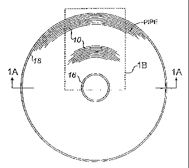
Fig. 1'shows a plan layout of the bottom two layers of the pioposed specific
coiling system;
Fig. 1 A is a cross-section about the line marked 1 A in Fig. 1;
Fig. 1B is an exploded view of the area shown in dotted lines in Fig. 1;
Fig. 2 is an enlarged plan view of the outer transition portion of Fig. 1B;
Fig. 3 is an enlarged plan view of the inner transition portion of Fig. 1B;
Figs. 4a to 4g are a series of cross-sections about the lines marked 4a, 4b,
4c, 4d,
4e, 4f and 4g in Figs. 2 and 3; and
CA 02283007 2006-10-13
4
Fig. 5 is a reproduction of the computer program used to define exactly the
geometry,
lines and co-ordinates of Figs. 1 to 3; more particularly the mathematical
reduction
mechanism used to define the transition curves.
DETAILED DESCRIPTION OF PREFERRED EMBODIMENTS:
Referring now to the drawings, where corresponding similar parts are referred
to
by the same numerals throughout the different figures, the preferred
embodiments are
now described. It is also understood that the material employed to make the
pipe and its
connections will be ductile and not brittle at the proposed operating
temperatures. The
pipe and its connections may be fabricated from normal grade steel typically
X70. The
word comprising is inclusive and does not exclude other features being
present. The
indefinite article "a" does not exclude more than one of an element being
present. The
radius of the coiled pipe generally refers to the radius of the coil. When the
cross-
sectional diameter of the pipe is referred to, it is referred to as the
diameter of the pipe. It
will be understood that a continuous coiled pipe will be made of pipes welded
together to
make it continuous.
Figs. 1 to 1 B depict various views of a portion of the bottom two layers of a
generally
circular continuous length of small pipe. Other pipe layers subsequently lie
on these
bottom layers and their plan projected lines fall either on the first layer,
shown solid lined
if the layer is odd numbered, or on the dotted transition lines and the solid
lines if the
layer is even numbered. The coiled pipe of a subsequent layer lies directly
upon and
aligned with the coiled pipe of a previous layer, except in the transition
zone to be
described. There is thus a linear contact zone between pipe in succeeding
layers that
distributes the weight of the pipe in an optimal manner.
The first layer 10 begins with a small pipe with intemal radius RR,;n 12 and
describes a half circle. The center of curvature is then abruptly shifted by
half the pipe
and the radius is also increased by half a pipe. This results in bringing the
inside of pipe
exactly tangential as shown at 16 to the outside of the start of the pipe
spiral 10. Thus the
path of the pipe has moved out one pipe diameter in one sweep of 360 degrees
by the use
of two specific half circles. This reduces the complexity of input to the
bending rollers,
which impart the prescribed bending curvature, to two constants. The bottom
layer
CA 02283007 1999-09-22
proceeds outwards in this manner with ever increasing half circles. When the
pipe
reaches the outside of the container 18 it is forced to rise up and land
directly on top of
the outside of layer one 20 and then it continues around as layer two until it
reaches the
start of the transition zone 22. Then by the path dictated by a prescribed
mathematical
5 formula, as outlined in Figs 2, 3 and. 5, it leaves the pipe directly
underneath in a
horizontally tangential fashion and joins tangentially and immediately above
the pipe
beneath, but some two pipe diameters inwards.
This transition shown A B C is accomplished within a distance of about 12 pipe
diameters and receives point crossover support at the point B.
This short transition length means that only 3% of the coiling has
continuously
changing curvature. The arrows 26 show how by moving inwards by two pipe
diameters
and by moving back outwards by one that even layers have a net inwards spiral
translation even though they lie directly on top of and aligned with an
outwards spiral for
about 94% of the time. The following are some summary statements relating to
Fig 1:
= Odd layers spiral outwards and even layers spiral inwards.
= Odd layers have no transition zones.
= Even layers have a transition zone equal to approximately 12 pipe diameters.
= About 97% of the coiling uses pure circular curvature.
= Outside of the transition zone, which represents about 94 % of the total
coiling, all
pipes in each layer, (about 40 or more layers), lie directly on top of one
another.
= Throughout the entire coiling system, both inside and outside of the
transition
zone, the radius of curvature is greater than about 11 diameters. This is true
also
where layers change from one to another. Hence the maximum bending strain does
not exceed a certain prescribed limit of approximately 5%.
= Where a lower layer rises to a higher layer, at the outside and at the
inside, the
transition equation (in Fig. 5) is also used. However it is combined with two
short
reverse circular arcs joined by a tangent, in the vertical plane to
accommodate the rise
as well as the lateral translation.
= At the outside, rising layers go from odd to even and at the inside rising
layers go
from even to odd.
CA 02283007 2006-10-13
6
= Every 180 degrees, in the odd layers, the radius of curvature changes
abruptly by
an amount equal to one half-pipe diameter. Additionally the center of
curvature
changes by an equal amount, thus pennitting a total radial translation of one
pipe
diameter after 360 degrees.
The references to even and odd layers can be interchanged by inserting the
transition
zone in the lowermost layer, but this is slightly disadvantageous since the
bottom most
layer will then suffer greater stresses on the lowest cross-over points than
if they were in
the second layer.
Fig. 2 is an enlargement of the outer portion of the transition area of Fig.
1B. The
basic transition generalized equation 28 is quoted and the mechanics of the
solution 30 is
depicted in Fig. 5. Depicted in Fig. 2 also is the simple fiznction 32 that
describes the pure
half circles that make up 97% of the coiling geometry. Position cross-sections
A B C are
shown and these can be tracked later in Figs. 4a to 4c to complete the three-
dimensional
picture. Fig. 2 also shows the outer wall 18 of the container and its
accompanying
transitional nature.
Fig. 3 is an enlargement of the inner portion of the transition area of Fig.
1B. The
section locations D E F G are shown and later depicted in Figs. 4d to 4g. The
generalized
transition function 28 is exactly the same as in Fig. 2 however the specific
values of the
constants are different numerically. This numerical difference results in
transition curves
that do not have reverse curvature, as is the case with the outer transition
curves.
Figs. 4a to 4g depict the bottom 4 or 5 layers at the inside and outside of
the
coil container vessel. Tracking pipe number 6 for instance depicts the paths A
B C and
D E F G shown in the first three figures. Tracking of pipe number 4 in
sections A, B
and C shows how the first layer changes into the second layer. Here it can be
seen
why only odd layers rise at the outside. Similarly it can be observed that
only even
layers rise at the inside.
A more detailed description of Figs. 4a to 4g now follows. The start of the
pipe coil can be
seen in section F at the pipe with the number 1 in its center. Section G
immediately above
shows pipe number 1 and this portion of the pipe is placed shortly after that
in section F.
The next portion of pipe placed is seen in section D and is numbered 2 in its
center. After
that the next portion is in section E and is shown numbered 2 in its center.
Thus the
CA 02283007 1999-09-22
7
sequence of how the pipe is placed at the start of the bottom or first layer
can be
described as Fl, (meaning section F, pipe number 1), Gl, D2, E2, F2, G2, D3,
E3, F3,
G3, D4, E4, F4, G4. This procedure is continued outwards one pipe diameter at
a time
until position A1 in section A is reached. The finishing placement sequence
for the first
layer can be described as Al, B1, C1, A2, B2, C2, A3, B3, C3, and A4. Thus
this
describes the placement of the first layer which winds outwards. The pipe then
rises up
and begins to move inwards in the second layer. The sequence is given by B4,
C4, A5,
B5, C5, A6, B6, C6, A7, B7, C7, A8, B8, and C8. This procedure is continued
inwards
one pipe diameter at a time until position D5 in section D is reached. The
finishing
placement sequence for the second layer can be described as D5, E5, F5, G5,
D6, E6, F6,
G6,. The pipe then starts to rise up at D7 and reaches the third layer at E7,
whereupon the
outwards moving sequence becomes F7, G7, D8, E8, F8, G8, D9, E9, F9, G9. The
rest of
the coiling continues in a similar fashion outwards and inwards following the
sequence
A9,B9,C9,A10,B10,C10,Al1,B11,C11,A12,B12,C12,A13,B13,C13,A14,B14,
C14, A15, B15, C15, A16, B16,C16......... D10, E10, F10, G10, D11, El1, F11,
G11,
D12, E12, F12 and G12. Only the first five layers are represented in Fig. 4.
The pattern
repeats itself for as many layers as are required, typically 20 or 30.
Fig.5 depicts a brief program, written in basic language, which describes the
geometry shown in the first three figures. The print functions are graphical
but the output
can be easily expressed in a numerical co-ordinate system. The principal
feature of the
program 30 between lines 190 and 400 is the mathematical description of how
the
constants for the transition equation are solved. The solution method is
essentially a
variation of a standard Gaussonian reduction method. The actual general
equation 28 is
unique to this process of coiling. Also the exponent (D, in line 240) used in
the equation
is unique in that it can be used as a tuning parameter to provide almost
perfect nesting of
the pipe in the transition zone.
It will be thus seen that the invention provides:
A specific method or system of coiling small diameter pipe having a long
continuous length of small diameter pipe approximately 10 miles (approximately
5 to 8
inches in diameter).
CA 02283007 1999-09-22
8
About 97% of the pipe is bent to a constant curvature over intervals of
approximately 180 degree arcs (such simplicity of constant curvature greatly
reduces the
cost of construction).
A unique transition method (for about 3% of the coil length) enables about 94%
of the pipe to lie directly beneath or on top of another pipe. Such a stacking
pattern
greatly reduces local bending and crossover stresses and thus reduces the
overall wall
thickness of the pipe or increases the permissible stacking height in each
container.
A method of coiling pipe that continuously spirals outwards and inwards by the
use of stepped constant curvature for approximately 97% of it's total length.
A mathematical method for describing the specific coiling geometry.
Although the coils are shown in constant radius half circles, these could be
segments of 360/n degrees, with each segment increasing in diameter 1/n pipe
diameters,
where n is greater than 1, but each increase of n over 2 increases the number
of pipe bend
settings and is not preferred. In the containment structure produced by this
method, coiled
pipe in any kth segment abuts coiled pipe in the k+nth segment for each kth
segment
except segments forming an outer boundary of the containment structure, to
thus form a
gapless structure. Although an embodiment has been shown in which the
transition zone
occupies 12 pipe diameters, advantages are still believed to be obtained when
the
transition zone occupies less than 50 pipe diameters.
The coiled pipe forms a containment structure that will normally be provided
with
valves 37 at either end of the pipe. The coiled pipe is suitable for the
containment of gas.
The coiled pipe is preferably enclosed within the container 18, which is
preferably sealed
to provide a secondary contairlment structure, and equipped with leak
detection
equipment.
The invention has now been described with reference to the preferred
embodiments and substitution of parts and other modifications will now be
apparent to
persons of ordinary skill in the art. Accordingly, the invention is not
intended to be
limited except as provided by the appended claim.