Language selection

Search

Patent 2283027 Summary

Third-party information liability

Some of the information on this Web page has been provided by external sources. The Government of Canada is not responsible for the accuracy, reliability or currency of the information supplied by external sources. Users wishing to rely upon this information should consult directly with the source of the information. Content provided by external sources is not subject to official languages, privacy and accessibility requirements.

Claims and Abstract availability

Any discrepancies in the text and image of the Claims and Abstract are due to differing posting times. Text of the Claims and Abstract are posted:

  • At the time the application is open to public inspection;
  • At the time of issue of the patent (grant).
(12) Patent Application: (11) CA 2283027
(54) English Title: ANGLED OPTIC FIBER UNIONS AND JUNCTIONS FOR OPTIC FIBER CONDUITS
(54) French Title: UNIONS ET JONCTIONS DE FIBRES OPTIQUES COUDEES POUR DES CONDUITS DE FIBRES OPTIQUES
Status: Deemed Abandoned and Beyond the Period of Reinstatement - Pending Response to Notice of Disregarded Communication
Bibliographic Data
(51) International Patent Classification (IPC):
  • G02B 6/36 (2006.01)
  • G02B 6/44 (2006.01)
(72) Inventors :
  • HICKEY, KURT A. (United States of America)
(73) Owners :
  • BAKER HUGHES INCORPORATED
(71) Applicants :
  • BAKER HUGHES INCORPORATED (United States of America)
(74) Agent: MARKS & CLERK
(74) Associate agent:
(45) Issued:
(22) Filed Date: 1999-09-22
(41) Open to Public Inspection: 2000-03-22
Examination requested: 2001-08-27
Availability of licence: N/A
Dedicated to the Public: N/A
(25) Language of filing: English

Patent Cooperation Treaty (PCT): No

(30) Application Priority Data:
Application No. Country/Territory Date
60/101,418 (United States of America) 1998-09-22

Abstracts

English Abstract


Angled unions and junctions for conduits in which fiber optic
conductors are run are provided for downhole oil drilling, injection and
production operations. The unions and junctions provide high pressure and
adverse condition protection for the optic fibers while providing an
acceptable bend radius.


Claims

Note: Claims are shown in the official language in which they were submitted.

-6-
CLAIM 1. An optic fiber conduit junction comprising:
a primary conduit having an axial passage therein; and
a branch conduit extending from said primary conduit and
having an axial passage which intersects said primary conduit axial passage,
said branch conduit axial passage creating an angle of intersection with said
primary conduit axis passage of about less than 90 degrees.
CLAIM 2. An optic fiber downhole distribution system comprising:
at least one optical fiber;
at least one length of first conduit for said optical fiber;
at least one junction connected to said first conduit, said
junction having at least one axial passage extending therethrough and at least
one second passage intersection said first passage at an angle 2 of about less
than 90 degrees.
CLAIM 3. An optic fiber downhole distribution system as claimed in
claim 2 wherein said at least one optical fiber is a plurality of optic and
fibers
distributed in said first passage and said second passage.
CLAIM 4. An optic fiber downhole distribution system as claimed in
claim 3 wherein said at least one junctions is a plurality of junctions each
receiving distributed fibers.
CLAIM 5. An optic fiber conduit junction comprising:
a housing;
a primary opening through said housing;
a secondary opening extending from an edge of said housing
into said housing to intersect with said primary opening, said secondary
opening forming an acute angle with said primary opening.

-7-
CLAIM 6. An optic fiber conduit junction as claimed in claim 5, further
including a tertiary opening forming an acute angle with said primary
opening.
CLAIM 7. An optic fiber conduit junction as claimed in claim 6 wherein
said secondary opening and said tertiary opening each form a plane with said
primary opening. and wherein the planes formed are intersecting.
CLAIM 8. An optic fiber conduit junction as claimed in claim 1 wherein
said junction includes ends which are pressure sealably securable to other
conduit sections.
CLAIM 9. An optic fiber downhole distribution system as claimed in
claim 2 wherein said system is pressure sealed to prevent fluid ingress or
egress from said system at connections between said at least one first conduit
and said at least one junction.
CLAIM 10. An optic fiber conduit junction as claimed in claim 5 wherein
said junction includes ends which are pressure sealably securable to other
conduit sections.

Description

Note: Descriptions are shown in the official language in which they were submitted.


CA 02283027 1999-09-22
ANGLED OPTIC FIBER UNIONS AND JUNCTIONS FOR OPTIC FIBER
CONDUITS
Background of the Invention
Field of the Invention
The invention relates to the oil field industry. More particularly, the.
invention relates to fiber optics, conduits and junctions for use in the
downhole environment.
t 0 Prior Art
In recent years fiber optic technology has been integrated into many
different fields of endeavor particularly with respect to communicating
information and power. Gains can be had on both fronts by employing optic
fibers instead of wire conductors in many situations.
As one skilled in the use of optic f bers will recognize, the fibers are
delicate and require protection to work reliably. For this reason it has been
very difficult to employ optic fibers in the typically harsh downhole oil well
environment. Temperature, pressure, vibration, chemicals, etc. are all
common conditions downhole and are all deleterious to virtually all materials
but particularly so with respect to delicate optic fibers.
Optic f bers have nevertheless been successfully ernpIoyed in the
downhole environment when properly clad and when run through empty
hydraulic control conduit systems. This use has been successful for straight
runs. The conduit protects the fiber from all of the aforementioned
conditions and reliable fiber optic control has been achieved. The limited (to
straight runs) downhole optic fiber usage has been very beneficial to the
industry but remains limited, in the knowledge of the industry, since until
this
invention there has been no way to successfully split fiber off a main run to
go in another direction. Running fiber in a primary wellbore and then

CA 02283027 1999-09-22
splitting off some of it for a lateral has never been successfully attempted
due
to breakage of the fibers and vibration coupling. Existing hydraulic conduit
"T" fittings when employed to split off fiber cause the fiber to break from
contact with corners and tight bend radiuses and because they suffer vibration
damage from contacting the walls of the conduit where vibration from the
environment is strongest with respect to the space defined by the conduit.
Summary of the Invention
The above-identified drawbacks of the prior art are overcome or
alleviated by the angled optic fiber conduit unions and junctions of the
invention.
Appropriately angled unions and junctions enable the heretofore
contraindicated practice of splitting optic fibers off from the main conduit
in
the downhole environment to be directed to distinct places such as lateral
I S boreholes or to other tools. Creating unions and junctions that maintain a
minimum bend radius and to avoid significant corner contact pressure makes
optic fiber distribution feasible and reliable in the downhole environment.
Although it is possible to split off optic fibers with conventional
hydraulic conduit unions and junctions the fiber bend radius is relatively
2o small, corner contact results and the fiber is pressed against one of the
walls
of the hydraulic conduit causing greater vibration coupling into the fiber.
While the optic fibers can be made to work in this condition in the factory,
the downhole environment in which these tools are employed is an
environment of high pressure, high temperature and high vibration. These
25 conditions in combination with the relatively small bend radius and the
fiber
being pressed against the conduit sidewall, thus coupling the fiber to
vibration in the conduit, cause failure.
By carefully matching a bend in the union or junction to avoid too
small a bend radius and consequently avoiding fiber pressure against the wall

CA 02283027 1999-09-22
- 3 -
of the conduit, failure of the fiber occurs less often while allowing the use
of
optic fibers at all locations in a well even if the well is a multilateral
well.
For purposes of clarity, the bias contemplated herein is that supplied by the
fiber itself in the bent condition.
The invention greatly expands the capability of manufacturers to
build downhole systems with fiber optic communications.
In addition to bend radius the .unions of the invention as well as the
entirety of the fiber optic conduit is pressure sealed. This may be
accomplished by any known sealing method that prevents ingress or egress of
fluid. By sealing the conduit a protective fluid for the fiber optic could be
employed within the conduit or it can contain simply air or even a vacuum
and still prevent wellbore fluids from gaining entry thereto.
Brief Description of the Drawings
is Referring now to the drawings wherein like elements are numbered
alike in the several FIGURES:
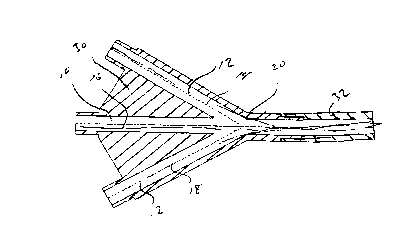
FIGURE 1 is a schematic cross section view of a junction of the
invention;
FIGURE 2 is an end view of the junction in Figure 1;
20 FIGURE 3 is a schematic cross section view of a two-way junction of
the invention; and
FIGURE 4 is an end view of the junction of Figure 3.
Detailed Description of the Preferred Invention
Referring to Figures 1 and 2, a schematic cross section view of a
three-way junction of the invention including primary conduit 10 and branch
conduits 12. Optic fibers, 14, l6 and.18 are visible, one in each conduit. The
branch conduits are joined preferably by web 30 or by an equivalent support
structure to provide sufficient strength. While the illustrations show both of

CA 02283027 1999-09-22
- 4 -
the branch conduits 12 extending in the same plane it is within the scope of
the invention to have each of the two branch conduits exist in different
planes
at a multiplicity of angles to one another. For example, viewing the drawing
of FIGURE 2, one of the branches is at the twelve O'clock position and one
of the branches is at the six O'clock position. These are in the same plane.
If
however, the second of the branches was at, for instance, the three O'clock
position, the two branch conduits would be in different planes.
Referring to Figures 3 and 4, a two-way junction is illustrated.
Numerals employed are identical to Figures 1 and 2 due to equivalence of the
parts. Each embodiment is connectable to another conduit 32 as illustrated
only in Figure 1 in known ways.
A preferable angle of departure for branch conduit 12 is illustrated as
angle 2 and is preferably in the range of about 10 to about 80 degrees and
preferably less than 90 degrees.
Angle 2, in addition ensures that fiber 16 does not bias itself into the
wall of the conduit 12 (with its bias to be straight). Because the fiber 16
when placed in the invention does not strongly contact conduit 12, coupling
of the vibration in the conduit from downhole operations is not well
transmitted to fiber 16. Fiber 16 therefore experiences far less vibration
than
would have been the case in the prior art conduits. Moreover, since contact
with the corner 20 is reduced due to angled departure, the fiber is not as
likely to break in this location.
In a prefen:ed embodiment of the invention, the fiber conduit is
pressure sealed at all joints thereof to insure complete fluid separation from
internal to the conduit and external to the conduit. Seals at joints of the
unions and other conduit sections may be tapered thread seals other metal-to-
metal seals, o-rings, teflon seals, etc. The seals preferably will withstand
up
to 10,000 psi or even higher so as to be sufficient to withstand downhole
pressures.

CA 02283027 1999-09-22
- 5 -
Optic fibers, because of the invention, are now available for use in all
areas of a well without premature workover. Optic fibers provide significant
advantage as known to the art and the art therefore is greatly benefitted.
Whilc preferred embodiments havc becn shown and described,
various modifications and substitutions may be made thereto without
departing from the spirit and scope of the invention. Accordingly, it is to be
understood that the present invention has been described by way of
illustration and not limitation.

Representative Drawing
A single figure which represents the drawing illustrating the invention.
Administrative Status

2024-08-01:As part of the Next Generation Patents (NGP) transition, the Canadian Patents Database (CPD) now contains a more detailed Event History, which replicates the Event Log of our new back-office solution.

Please note that "Inactive:" events refers to events no longer in use in our new back-office solution.

For a clearer understanding of the status of the application/patent presented on this page, the site Disclaimer , as well as the definitions for Patent , Event History , Maintenance Fee  and Payment History  should be consulted.

Event History

Description Date
Inactive: IPC from MCD 2006-03-12
Application Not Reinstated by Deadline 2005-11-14
Inactive: Dead - No reply to s.30(2) Rules requisition 2005-11-14
Deemed Abandoned - Failure to Respond to Maintenance Fee Notice 2005-09-22
Inactive: Abandoned - No reply to s.30(2) Rules requisition 2004-11-12
Inactive: S.30(2) Rules - Examiner requisition 2004-05-11
Amendment Received - Voluntary Amendment 2002-04-17
Letter Sent 2001-10-04
Request for Examination Received 2001-08-27
All Requirements for Examination Determined Compliant 2001-08-27
Request for Examination Requirements Determined Compliant 2001-08-27
Letter Sent 2000-07-17
Inactive: Single transfer 2000-06-21
Application Published (Open to Public Inspection) 2000-03-22
Inactive: Cover page published 2000-03-21
Inactive: Correspondence - Formalities 1999-12-22
Inactive: First IPC assigned 1999-10-28
Inactive: Courtesy letter - Evidence 1999-10-12
Filing Requirements Determined Compliant 1999-10-08
Inactive: Filing certificate - No RFE (English) 1999-10-08
Application Received - Regular National 1999-10-07

Abandonment History

Abandonment Date Reason Reinstatement Date
2005-09-22

Maintenance Fee

The last payment was received on 2004-09-08

Note : If the full payment has not been received on or before the date indicated, a further fee may be required which may be one of the following

  • the reinstatement fee;
  • the late payment fee; or
  • additional fee to reverse deemed expiry.

Please refer to the CIPO Patent Fees web page to see all current fee amounts.

Fee History

Fee Type Anniversary Year Due Date Paid Date
Application fee - standard 1999-09-22
Registration of a document 1999-09-22
Request for examination - standard 2001-08-27
MF (application, 2nd anniv.) - standard 02 2001-09-24 2001-09-05
MF (application, 3rd anniv.) - standard 03 2002-09-23 2002-09-06
MF (application, 4th anniv.) - standard 04 2003-09-22 2003-09-10
MF (application, 5th anniv.) - standard 05 2004-09-22 2004-09-08
Owners on Record

Note: Records showing the ownership history in alphabetical order.

Current Owners on Record
BAKER HUGHES INCORPORATED
Past Owners on Record
KURT A. HICKEY
Past Owners that do not appear in the "Owners on Record" listing will appear in other documentation within the application.
Documents

To view selected files, please enter reCAPTCHA code :


To view images, click a link in the Document Description column. To download the documents, select one or more checkboxes in the first column and then click the "Download Selected in PDF format (Zip Archive)" or the "Download Selected as Single PDF" button.

List of published and non-published patent-specific documents on the CPD .

If you have any difficulty accessing content, you can call the Client Service Centre at 1-866-997-1936 or send them an e-mail at CIPO Client Service Centre.


Document
Description 
Date
(yyyy-mm-dd) 
Number of pages   Size of Image (KB) 
Representative drawing 2000-02-23 1 9
Drawings 1999-12-22 2 34
Abstract 1999-09-22 1 9
Description 1999-09-22 5 166
Drawings 1999-09-22 1 26
Claims 1999-09-22 2 53
Cover Page 2000-02-23 1 30
Filing Certificate (English) 1999-10-08 1 164
Courtesy - Certificate of registration (related document(s)) 2000-07-17 1 115
Reminder of maintenance fee due 2001-05-23 1 111
Acknowledgement of Request for Examination 2001-10-04 1 194
Courtesy - Abandonment Letter (R30(2)) 2005-01-24 1 166
Courtesy - Abandonment Letter (Maintenance Fee) 2005-11-17 1 176
Correspondence 1999-10-08 1 15
Correspondence 1999-12-22 3 58