Language selection

Search

Patent 2283125 Summary

Third-party information liability

Some of the information on this Web page has been provided by external sources. The Government of Canada is not responsible for the accuracy, reliability or currency of the information supplied by external sources. Users wishing to rely upon this information should consult directly with the source of the information. Content provided by external sources is not subject to official languages, privacy and accessibility requirements.

Claims and Abstract availability

Any discrepancies in the text and image of the Claims and Abstract are due to differing posting times. Text of the Claims and Abstract are posted:

  • At the time the application is open to public inspection;
  • At the time of issue of the patent (grant).
(12) Patent Application: (11) CA 2283125
(54) English Title: A CORE STRUCTURE FOR AN INDUCTION HEATING ELEMENT
(54) French Title: STRUCTURE DE NOYAU POUR ELEMENT DE CHAUFFAGE PAR INDUCTION
Status: Deemed Abandoned and Beyond the Period of Reinstatement - Pending Response to Notice of Disregarded Communication
Bibliographic Data
(51) International Patent Classification (IPC):
  • H05B 6/12 (2006.01)
(72) Inventors :
  • ESKILDSEN, CHRISTIAN (Denmark)
(73) Owners :
  • AKTIEBOLAGET ELECTROLUX
(71) Applicants :
  • AKTIEBOLAGET ELECTROLUX (Sweden)
(74) Agent: SMART & BIGGAR LP
(74) Associate agent:
(45) Issued:
(86) PCT Filing Date: 1998-03-13
(87) Open to Public Inspection: 1998-09-17
Availability of licence: N/A
Dedicated to the Public: N/A
(25) Language of filing: English

Patent Cooperation Treaty (PCT): Yes
(86) PCT Filing Number: PCT/DK1998/000096
(87) International Publication Number: WO 1998041061
(85) National Entry: 1999-09-01

(30) Application Priority Data:
Application No. Country/Territory Date
0282/97 (Denmark) 1997-03-13

Abstracts

English Abstract


A dish-shaped core for an induction heating apparatus is provided with rim
parts which present a large area to the edge of the cooking vessel. These rim
parts are obtained by means of a slanted cut of the rim or by slanting the rim
itself inwards. The leakage flux is reduced because the edge of the cooking
vessel acts as an "attractor" for the flux lines emanating from the core.


French Abstract

Un noyau de forme évasée destiné à un appareil de chauffage par induction comprend des parties de couronne présentant une grande surface jusqu'au bord du récipient de cuisson. Ces parties de couronne sont obtenues au moyen d'une découpe oblique de la couronne ou par découpe oblique de la couronne elle-même vers l'intérieur. Le flux de fuite est réduit du fait que le bord du récipient de cuisson fait office d'"attracteur" pour les lignes de flux émanant du noyau.

Claims

Note: Claims are shown in the official language in which they were submitted.

4
CLAIMS
1. A core for an induction heating apparatus
comprising a core part having a rim, a bottom, and a
central pole piece, characterized in
that the rim structure presents a large area towards the
lower edge of the cooking vessel.
2. A core according to claim 1,
characterized in that the mean diameter
of the rim has essentially the same diameter as the
cooking vessel and the outer edge of the rim is raised
above the inner edge.
3. A core according to claim 2,
characterized in that both the lower
and the upper edge of the rim are disposed above the
surface of the cooktop.
4. A core according to claim 2 or 3,
characterized in that the outer edge of
the rim is rounded.
5. A core according to claim 1,
characterized in that the rim of the
core is inwards slanted and has a maximum diameter which
corresponds to the cooking vessel.

Description

Note: Descriptions are shown in the official language in which they were submitted.


CA 02283125 1999-09-O1
WO 98/41061 PCT/DK98/00096
1
indupote
A core structure for an induction heating element.
The invention relates to a core structure for an
induction heating element for use in a cooker for food.
Induction heating coils are well-known, comprising
as a minimum a flat "pancake" coil fitted below and
parallel to the cooking vessel. The magnetic field
around such a coil has large stray field which does not
contribute to the heating but rather heats up irrelevant
metal parts. In order to improve the situation it is
known to place a number of radially disposed ferrite
rods on the underside of the coil. In order to further
improve the functioning of this heating method, a more
complete core structure is known, being constituted of
a
shallow dish-shaped structure having an upwards-facing
rim and a central pole piece.
Particular losses are occuring because of the
stray field at the junction between the rim and the
cooking vessel. This stray field is considered undesired
and it is also under regulation in that it is considered
that it should exceed a certain maximum value. There is
hence a need to improve the magnetic coupling between
the core and the cooking vessel. The problem is that
without forcing the consumer to use cooking vessels
constructed in a particular manner, it is only possible
to use a change in the disposition of the core as a
parameter.
According to the invention a reduction of leakage
flux is obtained by means of a rim structure which
presents a large area towards the lower edge of the
cooking vessel. This has the effect that the edge of the
cooking vessel acts as an "attractor" for flux lines,
and hence reduces the flux which has to take a lengthy
path via the air. The pole piece area will in practice
be greater than the cross sectional area of the rim

CA 02283125 1999-09-O1
WO 98/41061 PCT/DK98/00096
2
itself, and this may e.g. be obtained by means of a
slanted cut of the rim.
In one advantageous embodiment of the invention,
the mean diameter of the rim has essentially the same
diameter as the cooking vessel and the outer edge of the
rim is raised above the inner edge.
In a further embodiment of the invention both the
lower and the upper edge of the rim are disposed above
the level of the cooktop. In this manner, an automatic
centering of a cooking vessel is obtained, and the
bottom of the cooking vessel is raised above the level
of the cooktop which prevents conductive heating of the
cooktop and the coil below the surface. Preferentially
the outer edge of the rim is rounded.
In a further advantageous embodiment of the
invention the rim of the core is inwards slanted and has
a maximum diameter which corresponds to the cooking
vessel. In this embodiment, the slanted rim is cut off
horizontally, and the core surface is essentially flush
with or raised slightly above the cooktop surface. The
area presented to the edge of the cooking vessel is
actually the outer side of the inwards slanting rim
part.
The invention will be described in greater detail
with reference to the drawing in which
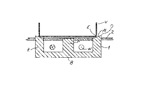
Fig. 1 shows an embodiment with inwards slanting
top of the rim , and
Fig. 2 shows another embodiment where the rim
itself is slanting.
In Fig. 1 is shown a core structure 1 which partly
penetrates a cooktop surface layer 2. The core structure
consists of a rim R, a bottom B and a central pole P. An
essentially toroidal cavity contains a winding W which
is one or several layers constituting a disc-shaped coil
concentric with the pole P.
The rim R is in the form of a cylindrical shell,
howver seen in a section as shown it is cut of obliquely

CA 02283125 1999-09-O1
WO 98141061 PCT/DK98/00096
3
at the top, i.e. the edge of the rim is part of a
conical surface A1. This surface presents a larger area
than would a plane section of the cylindrical rim. The
surface A1 faces the edge E of a cooking vessel V, which
contains ferromagnetic material, and the flux lines
exiting from the surface A1 is drawn towards the
concentration of ferromagnetic material at the edge E.
This reduces the stray flux around the core/cooking
vessel union established, and hence increases
efficiency. Provided the rim is sufficiently thick, a
plane section would provide a similar field
distribution, however the inwards facing surface A1
ensures centering of the cooking vessel V on the core.
Furthermore, the fact that the edge E rides on the
surface A1 means that there is an airgap below the
cooking vessel which creates heat insulation so that the
core 1 and winding W do not receive heat conducted from
the heated cooking vessel. The outer edge O of the rim
may advantageously be rounded in order to increase
cleanibility, and the central pole P may be extended to
almost touching the cooking vessel, possibly having a
rounded top surface, again to increase cleanability.
In Fig. 2 a different embodiment of a core
according to the invention is shown. The reference
numerals are as for Fig. 1, however the part of the core
interacting with the edge E of the cooking vessel V is
not the top of the rim but rather the outside surface A2
of the inwards slanting rim R. This surface A2 is in
practice essentially conical, although a smooth rounding
is also perfectly feasible. All the parts which
penetrate the cooktop surface 2 are rounded in order to
improve cleanability. The core is preferably moulded in
a material which is either a polymer or a densit
material loaded with ferromagnetic particles, such as
ferrite which has a high permeability. The winding W is
surrounded by an insulating material which is cast in
situ.

Representative Drawing
A single figure which represents the drawing illustrating the invention.
Administrative Status

2024-08-01:As part of the Next Generation Patents (NGP) transition, the Canadian Patents Database (CPD) now contains a more detailed Event History, which replicates the Event Log of our new back-office solution.

Please note that "Inactive:" events refers to events no longer in use in our new back-office solution.

For a clearer understanding of the status of the application/patent presented on this page, the site Disclaimer , as well as the definitions for Patent , Event History , Maintenance Fee  and Payment History  should be consulted.

Event History

Description Date
Time Limit for Reversal Expired 2004-03-15
Application Not Reinstated by Deadline 2004-03-15
Inactive: Abandon-RFE+Late fee unpaid-Correspondence sent 2003-03-13
Deemed Abandoned - Failure to Respond to Maintenance Fee Notice 2003-03-13
Letter Sent 2001-03-23
Reinstatement Requirements Deemed Compliant for All Abandonment Reasons 2001-03-15
Deemed Abandoned - Failure to Respond to Maintenance Fee Notice 2001-03-13
Letter Sent 2000-02-25
Inactive: Single transfer 2000-01-28
Inactive: Cover page published 1999-11-05
Inactive: First IPC assigned 1999-10-29
Inactive: Courtesy letter - Evidence 1999-10-19
Inactive: Notice - National entry - No RFE 1999-10-13
Application Received - PCT 1999-10-08
Application Published (Open to Public Inspection) 1998-09-17

Abandonment History

Abandonment Date Reason Reinstatement Date
2003-03-13
2001-03-13

Maintenance Fee

The last payment was received on 2002-03-13

Note : If the full payment has not been received on or before the date indicated, a further fee may be required which may be one of the following

  • the reinstatement fee;
  • the late payment fee; or
  • additional fee to reverse deemed expiry.

Please refer to the CIPO Patent Fees web page to see all current fee amounts.

Fee History

Fee Type Anniversary Year Due Date Paid Date
Basic national fee - standard 1999-09-01
Registration of a document 2000-01-28
MF (application, 2nd anniv.) - standard 02 2000-03-13 2000-03-06
MF (application, 3rd anniv.) - standard 03 2001-03-13 2001-03-15
Reinstatement 2001-03-15
MF (application, 4th anniv.) - standard 04 2002-03-13 2002-03-13
Owners on Record

Note: Records showing the ownership history in alphabetical order.

Current Owners on Record
AKTIEBOLAGET ELECTROLUX
Past Owners on Record
CHRISTIAN ESKILDSEN
Past Owners that do not appear in the "Owners on Record" listing will appear in other documentation within the application.
Documents

To view selected files, please enter reCAPTCHA code :


To view images, click a link in the Document Description column. To download the documents, select one or more checkboxes in the first column and then click the "Download Selected in PDF format (Zip Archive)" or the "Download Selected as Single PDF" button.

List of published and non-published patent-specific documents on the CPD .

If you have any difficulty accessing content, you can call the Client Service Centre at 1-866-997-1936 or send them an e-mail at CIPO Client Service Centre.


Document
Description 
Date
(yyyy-mm-dd) 
Number of pages   Size of Image (KB) 
Representative drawing 1999-11-05 1 7
Description 1999-09-01 3 153
Abstract 1999-09-01 1 57
Drawings 1999-09-01 1 30
Claims 1999-09-01 1 26
Cover Page 1999-11-05 1 37
Reminder of maintenance fee due 1999-11-16 1 111
Notice of National Entry 1999-10-13 1 193
Courtesy - Certificate of registration (related document(s)) 2000-02-25 1 115
Courtesy - Abandonment Letter (Maintenance Fee) 2001-03-23 1 182
Notice of Reinstatement 2001-03-23 1 169
Reminder - Request for Examination 2002-11-14 1 115
Courtesy - Abandonment Letter (Request for Examination) 2003-05-22 1 167
Courtesy - Abandonment Letter (Maintenance Fee) 2003-04-10 1 176
Correspondence 1999-10-13 1 15
PCT 1999-09-01 9 364
Fees 2001-03-15 2 73